-
Paper Information
- Previous Paper
- Paper Submission
-
Journal Information
- About This Journal
- Editorial Board
- Current Issue
- Archive
- Author Guidelines
- Contact Us
Journal of Civil Engineering Research
p-ISSN: 2163-2316 e-ISSN: 2163-2340
2012; 2(5): 42-48
doi: 10.5923/j.jce.20120205.03
Equivalent Strut Width for Partial Infilled Frames
 Abstract
 Reference
 Full-Text PDF
 Full-Text HTML
Prachand Man Pradhan
Department of Civil and Geomatics Engineering, Kathmandu University, Dhulikhel, Nepal
Correspondence to: Prachand Man Pradhan , Department of Civil and Geomatics Engineering, Kathmandu University, Dhulikhel, Nepal.
| Email: |  |
Copyright © 2012 Scientific & Academic Publishing. All Rights Reserved.
The usual practice in the analysis of reinforced concrete frame structures is to analyze the frames with skeleton members comprising of only slabs, beams and columns. However, in reality the structures also possess masonry infills within most of the frames, but they are ignored in the models so as to minimize the computational works. Researchers have indicated that the frames comprising of masonry panels behave significantly stiffer as compared to bare frames. The infills contribute in stiffening the frames, but researches also show that the partial infills can cause adverse effect known as captive column effect. A lot of experimental evidences show that the captive column effect causes the partially infilled frames to damage during earthquakes. It is still a matter of interest to researchers to find out how much shear actually occurs at the location where the wall terminates. The shear force generated at the points where the wall terminates within the frame in the windward side causes the windward side column to fail. This study is done to identify the shear force values at such locations through analytical formula. The equivalent strut width as provided by various researchers is compared with the established formula for verification and further applied to obtain the shear forces at various locations in partially infilled frame. Equivalent strut width formulation is done in this paper, which may be used directly in the frame analysis wherever partially or fully infilled walls are provided.
Keywords: Equivalent Strut Width, Partially Infilled Frames, Lateral Resistance, Flexural Rigidity Model
Article Outline
1. Introduction
- In the analysis of Reinforced concrete framed structures, there is a trend of ignoring the existence of brick infill mainly due to the reasons of complicated computations. Only the frame is considered in the analysis, which actually saves tedious calculation time and effort, but the real existence of bricks within the frames being ignored, actually underestimates the capacity of the structure. From the past studies done by various researchers, it has been found that the brick infills actually contribute in enhancing the strength of the structure by resisting the lateral deflection of frames applied to horizontal forces. Again, the contribution has been felt primarily during the earthquake events, where, most of the infilled framed structures remain less damaged as compared to the frames which are left bare. It is also necessary to examine whether the contribution of infilled frames remain equally good when some openings are provided within the panels. Some past studies also have indicated that the infills which include voids tend to be less effective, although, better than with the bare frames. The contribution of brick infill has been studied in this paper, particularly for partially infilled one because, the partially infilled frames in the past earthquakes have shown damaging effects, contrary to the completely filled walls or even with small openings. Most of the buildings of such kind have failed in the past earthquakes[1]. The short-column-effect or the captive-column-effect, are identified as the basic reason for the damage during the times of earthquakes. It is also understood that large shear force affects the location within the column where the partial infill height terminates.
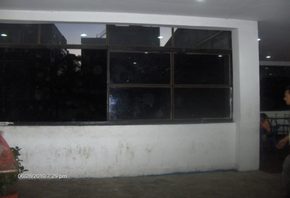 | Figure 1. Partially infilled framed structure |
2. Past Studies on Infilled Frames
- Numerous studies have been done both for fully infilled frames and for infills containing openings. Thomas (1952) and Ockleston (1955) were one of the early major contributors in connection to the interaction between wall and frame[3]. Holmes (1961) studied experimentally on steel frames infilled with brick masonry and reinforced concrete walls and developed semi-empirical design method for laterally loaded infilled frames based on equivalent strut concept. His tests suggested that brick masonry walls increase the strength of frame by around 100%. The infill was considered to fail in compression. The load carried by infill at failure was calculated by multiplying the compressive strength of material by the area of equivalent strut. He states that the width of equivalent strut to be 1/3rd of the diagonal length of infill, which resulted in the infill strength being independent of frame stiffness (Table 1). Smith[5] has put up tremendous effort in finding out the interaction between frame and infill. He tested a number of infilled frames subjected to diagonal loading where he used the diagonal strut concept. His design curve gives the effective width of strut, the compressive failure load and the diagonal failure load as related to frame stiffness and infill aspect ratio. Mainstone[6] has given equivalent diagonal strut concept by performing tests on model frames with brick infills. His approach estimates the infill contribution both to the stiffness of the frame and to its ultimate strength. The strut width equation according to him is shown in Table 1. Liauw and Kwan[7] studied both experimentally and analytically the behavior of non-integral infilled frames. Finite Element method was adopted to find the effects of nonlinearities of the material and the structural interface, the initial lack of fit and friction at the interface was considered. Paulay and Preistley[8] gave the width of diagonal strut as 0.25 times the diagonal length of the strut (Table 1). Hendry[9] has also presented equivalent strut width that would represent the masonry that actually contributes in resisting the lateral force in the composite structure (Table 1). In addition to these studies, large numbers of researches have been done in the past for fully infilled frames with and without openings. In the equations given in Table 1, H is the height of the frame, θ is the angle made by the strut with the horizontal, Ec and Ic are the Young’s modulus and Moment of inertia of column respectively and Em, t and hm are the Young’s modulus, thickness and height of masonry infill respectively. In Hendry’s equation, αh and αL are the contact length between wall and column and beam respectively at the time of initial failure of wall.
3. Analytical Approaches
- This study commences with the hypothesis that the flexural rigidity of infill should be equal to the flexural rigidity of frame in order to have equilibrium in the structure. Since the wall height is not full, the partial height wall will be providing significant resistance to the columns when the frame is laterally loaded until the wall gets initial crack. The partially infilled wall restrains the lateral deflection of the frame up to the height of the wall, but the lateral force which actually is acting on the top node of the frame equal to the base shear will try to deflect the void portion of the frame. In this instant, the top of the frame gets deflected while the junction between the column and wall will remain less affected until the wall cracks. So, the effort has been done to find out how the columns get sheared due to the shear force action by the restraining diagonal at the junction. From the fundamental concept of deflection theories when a cantilever is loaded at free end, in order to avoid deflection at free end, large opposing force need to be applied by props and this phenomenon is analogous to the case where the masonry wall behaves like prop to the frame elements. Wherever the wall terminates, the vertical component of the diagonal strut will be the propping force which is actually the shear force acting in the column which causes the column to fail during the lateral force application to the portal frame.
3.1. Formulation
- When the wall height doesn’t extend up to the top beam level, the lateral force applied to the composite structure will cause deflection of the concrete frame laterally, which further compresses the infill frame diagonally as shown by Rs (Fig. 3a). Since the void portion above the wall is not compressed by the beam, only the wall adjacent to the column will be compressed, which indicate that the strut effectively working will be as shown in the figure (Fig. 3b). If the flexural rigidities of frame and masonry wall are compared the equivalent width of the wall contributing in the resistance against deflection can be obtained. According to elastic strip theory, the contact length between frame and masonry kx is given by:
 , where hy is the equivalent length of wall (Fig.2) that contributes in compression[13].
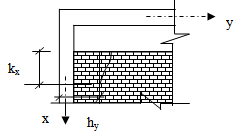 | Figure 2. Contact length between frame and masonry |
 | (1) |
 | (2) |
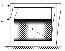 | Figure 3(a). Effect in partial infilled frame |
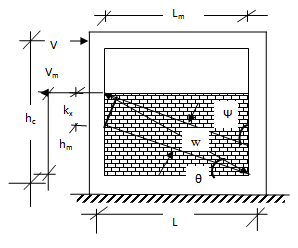 | Figure 3(b). Analytical model for equivalent strut |
4. Results and Discussions
4.1. Comparisons with Various Researchers’ Findings for Full Infill
- The formulation for strut width has been compared with the formulae suggested by various researchers. The Table 2 indicates the data assumed to calculate the equivalent strut width for the comparison purpose. It is observed that the equivalent strut width obtained by the Flexural model is very much close to the results compared to those suggested by Paulay and Priestley[8], Holmes[4], Liauw and Kwan[7] and Hendry[9]. The observation from Fig. 5 is regarded as the condition for validity of the formulated equation 1.
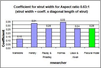 | Figure 4. Coefficient for strut width for aspect ratio 0.63:1 |
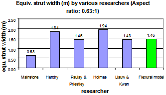 | Figure 5. Equivalent strut width by various researchers |
|
| ||||||||||||||||||||||||||||||||||||||||||||||||||||||||||||||||
4.2. Shear Forces and Strut Widths for Partial Infilled Frame
- In this study, a single bay, single storey reinforced concrete frame is considered as given in Table 4. It is assumed that if a partial height infill is included within a frame and if the frame is applied with some lateral load, the wall will tend to resist the deflection due to the resistance provided by the frame in composite manner. While V is the force applied to the composite structure, we consider Vm is the resistance offered by the wall up to which it has been constructed. The force V tends to deflect the structure laterally while the resisting force Vm tends to resist the whole structure from being deformed. During this phenomenon, the structure obviously gets benefited by the resistance offered by the wall. When there is resistance at the junction of the wall and column, it is possible that the junction will face significant moment. This moment will be sufficient for damaging effect in the concrete column if designed brittle or disregarding ductility. Various parameters are considered as per Table 4 for the study.In this study, a single bay, single story reinforced concrete frame is considered as given in Table 4. It is assumed that if a partial height infill is included within a frame and if the frame is applied with some lateral load, the wall will tend to resist the deflection due to the resistance provided by the frame in composite manner. While V is the force applied to the composite structure, we consider Vm is the resistance offered by the wall up to which it has been constructed. The force V tends to deflect the structure laterally while the resisting force Vm tends to resist the whole structure from being deformed. During this phenomenon, the structure obviously gets benefited by the resistance offered by the wall. When there is resistance at the junction of the wall and column, it is possible that the junction will face significant moment. This moment will be sufficient for damaging effect in the concrete column if designed brittle or disregarding ductility. Various parameters are considered as per Table 4 for the study.The formula by Flexural model holds well until pre-cracking stage. A study is done for a particular model considered by Agarwal and Shrikhande[15], and it is observed by using the equation 1, that the equivalent strut width for 2550 mm tall masonry infill (full infill) of length 4550mm will be 805.222 mm while the strut width used by Hendry’s equation is 778.4mm. This indicates that the strut width may be taken as 0.154 times the diagonal length in this case. Further it indicates that the strut width value depends upon Young’s modulus of the materials as well as the aspect ratio between the frame height and span. The strut width value and shear forces at various levels of infill for various aspect ratios are computed and tabulated in Table 5.
|
| |||||||||||||||||||||||||||||||||||||||||||||||||||||||||||||||||||||||||||||||||||||||||||||||||||
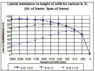 | Figure 6. Comparative graph between lateral resistance and height of infill |
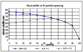 | Figure 7. Comparative graph between strut width and percentage partial opening |
5. Conclusions
- The suggested formula (1) gives an idea that the infill would be resisting the deflection of the frame and thus, the global structure gets strengthened against lateral deflection. However, when the infill height gets reduced, then the action against the columns would be different at different aspect ratios between the frame height and the frame span. It is found that the strut width for various masonry heights within concrete frames can be determined analytically and then it can be used for analyzing infilled frames conveniently. The value of strut width should be assigned separately for various percentage openings, but beyond 70% opening, the strut width will be almost same for all aspect ratios and the composite frame will behave just similar to bare frame. The strut width value depends much upon the aspect ratio as well as other material parameters. The lateral strength offered by the infill depends on the height of the wall and as the height of wall reduces, it is found that the resistance capacity gradually increases till nearly 70% of the wall is left open. This shows the short column effect on the frame offered by the partial infill. It is also to be noted that the shear force offered by partial infills where the wall terminates can be obtained using the equation 2 as shown in Table 5.The capacity of composite frame increases due to the additional resistance offered by infill when lateral load is applied. The partial infilled frames are liable to damage during lateral load application due to the shear force at columns transferred by the partial wall in higher aspect ratios (more than or equal to 1:1). When the infill is not provided the masonry infill’s capacity will not be active and only the bare frame has to resist the lateral force. This study limits to static loading condition, however, further study may be done for dynamic case. With the help of the equivalent strut width obtained from this research, computer analyses for structures inclusive of partial infills will be possible by incorporating them in the analytical models. The realistic responses of partially infilled frames may thus be obtained.
References
| [1] | Guevara L.T. and Garcia L.E., “The captive and short column effects”, Earthquake Spectra, Vol.21, No. 1, pp. 141-160, 2005. |
| [2] | Ghassan Al-Chaar, “Evaluating strength and stiffness of unreinforced masonry infill structures”, Construction Engineering Research Laboratory, ERDC/CERL TR-02-1, US Army Corps of Engineers, 2002. |
| [3] | Sahlin S., “Structural Masonry”, Prentice Hall, Inc. Eaglewood Cliffs, New Jersey, USA, 1971. |
| [4] | Holmes M., “Steel Frames with brickwork and concrete infilling”, Proceedings of the Institution of Civil Engineers, 473-478 (eISSN 1753-7789), 1961. |
| [5] | Smith B.S., “Lateral stiffness of infilled frames”, Journal of the Structural Division, ASCE, Vol.88, No. St-6., pp.183-199, 1962. |
| [6] | Mainstone R.J., “On the stiffnesses and strengths of infilled frames”, Proceedings of the Institution of Civil Engineers, Supplement (V), pp. 57-90, 1971. |
| [7] | Liauw T.C., and Kwan K., “Non-linear behavior of non-Integral infilled frames”, Computers and Structures, Vol.18, No.3, pp.551-560, 1984. |
| [8] | Paulay T. and Priestley M.J.N., “Seismic design of concrete and masonry buildings”, John Wiley and Sons Inc. New York. 1992. |
| [9] | Hendry A.W., “Structural Masonry”, 2nd ed. Macmillan Press. 1998. |
| [10] | Huang C.H., Tuan Y.A. and Hsu R.Y., “Nonlinear Pushover Analysis of Frames”, Earthquake Engineering and Engineering Vibration, Vol.5, No.2, Article ID; 1671-3664, 02-0245-11, 2006. |
| [11] | Taher S., El-Din and Afefy H.M., “Role of masonry infill in seismic resistance in RC structures”, The Arabian Journal for Science and Engineering, Vol.33, No. 2B, Egypt, 2008. |
| [12] | Subramanian K. and Jayaguru C., “Lateral behavior of partially infilled reinforced concrete frames with masonry inserts”, African Journal On Line (AJOL), Journal of Civil Engineering Research and Practice, ISSN: 1729-5769, Vol. 6, No.2. 2009. |
| [13] | Pubal Z.K., “Theory and calculation of frame structures with stiffening walls”, Elsevier Science Publishers, The Netherlands. 1988. |
| [14] | FEMA 273, Seismic rehabilitation guidelines, Systematic Rehabilitation, Chapter 7, Clause 7.3.2.1, 1997. |
| [15] | Agarwal P. and Shrikhande M., “Earthquake resistant design of structures”, Prentice Hall of India Pvt. Ltd., India, 2006. |