-
Paper Information
- Next Paper
- Previous Paper
- Paper Submission
-
Journal Information
- About This Journal
- Editorial Board
- Current Issue
- Archive
- Author Guidelines
- Contact Us
Journal of Civil Engineering Research
p-ISSN: 2163-2316 e-ISSN: 2163-2340
2012; 2(5): 31-41
doi: 10.5923/j.jce.20120205.02
Numerical Modelling and Analysis of Structural Behaviour of Wall-stud Cold-formed Steel Shear Wall Panels under In-plane Monotonic Loads
 Abstract
 Reference
 Full-Text PDF
 Full-Text HTML
Xianghe Dai
School of Engineering, Design and Technology, University of Bradford, UK
Correspondence to: Xianghe Dai , School of Engineering, Design and Technology, University of Bradford, UK.
| Email: |  |
Copyright © 2012 Scientific & Academic Publishing. All Rights Reserved.
This paper presents a numerical modelling method to predict the shear behaviour of typical wall-stud cold-formed steel wall panels subjected to in-plane monotonic loads. In the research presented in this paper, different material and mechanical properties for cold-formed steel sheets, self-drilling screwed connectors and wall fixing boundary conditions were considered to explore the influence of sheath sheeting, connectors and fixing boundary conditions on the structural behaviour of selected wall panels. After the FE model being validated against experimental results, a parametric study was conducted and the comparison and analysis highlight the effect of different sheaths, connectors on to the structural shear behaviour of typical wall-stud cold-formed steel wall panels.
Keywords: Numerical Modelling, Cold Formed, Wall Panel, In Plane Monotonic Load, Comparison
Article Outline
1. Introduction
- Cold-formed steel shear wall systems have been extensively used in lightweight steel construction. Although effective design recommendations for lightweight steel members and structures have been available, due to the specific characteristics of thin-walled sections and their assembly features, the stability of the thin-walled members, the failure modes of connections and the load-bearing capacity of overall structural wall systems are still attracting designers and researchers’ attention.When an individual cold-formed steel member suffers from a compressive or shear load, stability problem may occur if its slenderness ratio exceeds a curtain value or the normal or shear stress reaches a critical value. Extensive investigations[1~12] have been carried out to understand the characteristics and causes of this kind of instabilities including local buckling, global buckling and shear buckling etc. The results of previous researches have formed the current design consideration of cold formed steel members for use in modern construction. However, different from a simple structural element, a typical wall-stud cold-formed steel shear wall panel consists of a cold-formed wall stud frame, sheathing boards and other associated filling materials. The sheathing boards and stud frame are joined by connectors. This makes the panel being a composite member and thus its structural behaviour might be complicated. As one of the most important elements in a wall panel system, the connection has been investigated broadly to understand its mechanical behaviour, such as the fatigue strength properties of screwed and riveted connections under cyclic loads[13]. Conventional connectors for cold-formed steelwork, including the type of fasteners (connectors), modes of failure, basic testing methods and the influence of repeated loading on connection performance were summarised by Davies[14]. The sheathing board is an important member in a wall-stud cold-formed steel wall system. Sometimes it is named ‘structural skin’. According to their functions, sheaths can be divided into structural (mechanical) sheathing and non-structural (non-mechanical) sheathing. A structural sheath is generally a load-bearing element and it has appropriate strength and stiffness. A non-structural sheath, however, may be weaker and its load-bearing capacity might be ignored in design conservatively. The “Manual of Stressed Skin Diaphragm Design”[15] and ECCS[16] cover the design and analysis of important steel sheathed system. The behaviour of non-metal sheaths applied on cold-formed steel wall systems were also investigated by[17~25]. Generally, in a wall panel, the sheathing may restrain the local buckling of other frame members and thus to improve the overall stability of a structure. In practice a sheath provides substantial load-bearing capacity to the structural wall although in many design codes it is only included as a very conservative enhancement of the load-bearing capacity. It should be pointed out: the contribution of the sheath to the wall system depends on the connections. Stronger connections may allow a sheath contribute its maximum capacity. Unfortunately, in engineering practice, most connections failed before the sheathing reached its ultimate strength. In many cases, the failure of the overall structural wall initiated from the failure of connections.The research presented in this paper aims to develop a numerical method using to model the structural behaviour of typical cold-formed stud wall panels under in-plane loads. It includes the following aspects: (1) develop a numerical simulation method, (2) understand the effect of important constituent elements on the overall structural behaviour of typical wall-stud cold-formed steel wall panels.
2. Description and Validation of Numerical Method
- There is no doubt a full scale physical experiment may provide the most reliable insight into the understanding to the behaviour of structural members, however physical testing is expensive, time consuming and sometimes limited by the capacity of available equipment. Furthermore it will be very difficult to conduct extensive parametric studies by experiments. Therefore the development of numerical modelling method and its application in engineering research and practice are encouraged. This section will describe and validate the FE modelling method using to capture the structural behaviour of typical wall-stud cold-formed steel wall panels under in-plane monotonic load.
2.1. Typical Cold Formed Steel Wall Panel System
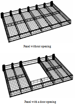
- As mentioned previously, lightweight steel wall panels have been broadly employed in modern constructions. A typical wall-stud cold-formed steel shear wall panel system consists of cold-formed wall studs, braces, fasteners, sheathing boards and infill materials for fire-resistance and insulation of sound and warmth etc. As shown in Figure 1[26], the full-sized stud wall panels involved in this research have a width 3600mm and depth 2440mm, comprised C-shaped cold-formed steel wall studs, corrugated cold-formed steel sheets, U-shaped cold-formed steel tracks, horizontal C-shaped cold-formed steel braces and self-drilling self-tapping screws (fasteners). Figure 2 gives the joint details and Figure 3 presents the sectional dimensions of main members and sheet profiles used. The typical stud wall panels presented in Figure 1 are also selected for the development and validation of the FE method in the research presented in this paper.As shown in Figure 1, the selected cold-formed steel stud wall panel without opening consists of 9 studs, 2 tracks, 6 horizontal braces and 3 pieces of corrugated steel sheets on one side. The stud wall panel with a door opening consists of 10 full-depth studs, as used in the panel without openings, and one short stud over the opening, 2 tracks, 4 horizontal braces, 1 door head and 5 pieces of corrugated steel sheets on one side. The fasteners for connecting the stud and track at each side of the wall panel are two pairs of SPEDEC SL4-F-4.8x16 (d=4.8mm) self-drilling self-tapping screws. The fasteners between the corrugated sheets and members (studs, tracks, braces) are SD3-T15-4.8-22 (d=4.8mm) self-tapping screws. As shown in Figure 1, the sheet ends are fixed to the frames in every trough. For the intermediate studs, the sheets are fixed to the frame at every other trough. The seam fasteners of sheet to sheet are SL2-T-A14-4.8x20 (d=4.8mm) screws, placed at 200mm spacing.
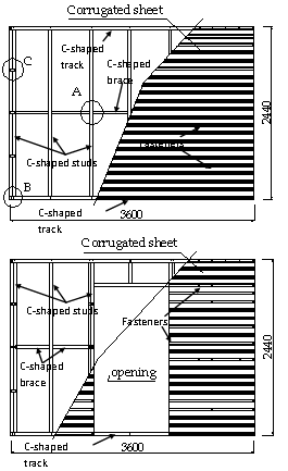 | Figure 1. Typical cold-formed steel stud wall panels |
2.2. Boundary Condition and Member Interaction
- In engineering practice, lightweight steel wall panels are generally fabricated in a factory and then transported to the construction site to erect via bolts. Following the experimental study[26] and construction practice, the wall panels investigated by the research given in this paper were fixed to the ground by bolts with strong “washer” plates through the bottom track. The in-plane monotonic load was applied through a stiffener loading track at the panel top and whose lateral (out of wall plane) translation was restrained. In corresponding to the experimental boundary conditions, in the FE modelling, the bottom track was pinned to the ground through 27 points to model the holding-down blots and washers and the load was applied to the top track via 7 points. The top track was restrained against the translation in the direction out of the wall panel plane which is identical to the experiment set-up.In the FE model, many contact pairs between members exist due to the wall panel is assembled by using multiple elements. When the wall panel is under load, these elements interact each other through their contacts and the interaction affects the overall structural behaviour. Therefore the contact function available in ABAQUS/Standard solverwas adopted to simulate the interaction between member and member. The contact was defined as surface-to-surface contact with a finite sliding option. “Hard contact” was assumed for the normal contact behaviour as no penetration. Different friction factors, from frictionless (friction factor = 0) to substantial friction (friction factors = 0.4 and 0.8) to large friction (“rough” option) were assumed for the contact behaviour in the tangential direction. It was found the effect friction coefficient was not very sensitive and therefore a friction factor of 0.4 was adopted in all the FE models.
 | Figure 2. Detailed configuration of joints A B C in wall-stud cold-formed steel stud wall panels |
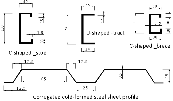 | Figure 3. Section dimensions of the main members used for the selected wall panels |
2.3. Modelling of Wall-Stud Panel Frame
- The frame is the skeleton of the panel system. Generally it bears the vertical loads applied at the wall top. Due to the thickness of the frame member is very small comparing to other dimensions, therefore 4-node shell elements available in the ABAQUS was adopted in the modelling. This reflects appropriately the deformable feature of the “thin-wall” members. The mesh sensitivity study indicated that shell element size less than 100x100mm for the steel studs and steel tracks was appropriate. Smaller element size such as less than 20x20mm did not improve the accuracy of the numerical results but needed much more time to complete an analysis. However the accuracy of the numerical results became worse if the element size was greater than 150x150mm. Therefore element dimension 100x100mm was adopted. The material properties of the original cold-formed steel members for the selected wall panels were tested by Fulop[26] and E=210000Mpa, Fy=445N/mm2, Dult=20% for cold-formed C-shaped suds, C-shaped braces and U-shaped trucks were suggested in numerical analysis.
2.4. Modelling of Steel Sheaths
- As mentioned in the previous sections, the vertical compressive load may be carried by the stud frame, however the in-plane shear load is generally carried by sheaths. Therefore in the selected steel stud wall panels, corrugated cold-formed steel sheet is one of the most important components, especially for the wall under in-plane load. As described previously, a wall panel sheath may be a structural sheathing or a non-structural sheathing. To promote the local buckling resistance and increase the vertical load bearing capacity, many sheaths with corrugated profile have special stiffener folds. This makes the panel wall system being complicated and causes difficulty in simple simulation and analysis. In the numerical modelling by using advanced commercial software packages, it is possible and exactly uses the shape and dimension of the sheaths, however more labour time and CPU time needed to build and run the FE model. Therefore the corrugated sheath usually is simplified into an equivalent orthotropic flat sheathing board with two elastic moduli in simple calculation and analysis. The research presented in this paper tried to check the feasibility of applying simplification methods developed by other researchers to cold-formed steel stud wall panels under in-plane shear loads. Based on the practical corrugated sheet profiles, the material properties of a simplified (equivalent) flat sheet are orthotropic, which means that the properties in the corrugation direction and in the direction perpendicular to the corrugation are different. In order to understand the effect of the sheets to the whole structural behaviour of a wall panel, different parameters for the equivalent sheet were adopted in the numerical analysis. Atrek and Nilson[27] proposed an acceptable method to determine the equivalent elastic moduli and which is described as following. As shown in Figure 4, axes 1 and 2 represent the direction perpendicular and parallel to the corrugation direction respectively.
 are the equivalent moduli of elasticity of the flat sheet in the directions following axes 1 and 2. The equivalent orthotropic elastic moduli for the corrugated steel sheet are described as:
 | (1) |
 : Poisson’s ratio of the original sheet material, P: pitch of corrugation (mm),
  : developed width of one corrugation (mm),
  : moment of inertia of one corrugation about its own mid-plane(mm4),
  : moment of inertia of the flat sheet with a width equal to the pitch of the corrugation about its own mid-plane (mm4), E0: modulus of elasticity of original sheet material (kN/mm2),
  : equivalent modulus of elasticity of the flat sheet in the direction perpendicular to the corrugation (kN/mm2),
  : equivalent modulus of elasticity of the flat sheet in the direction parallel to the corrugation (kN/mm2).
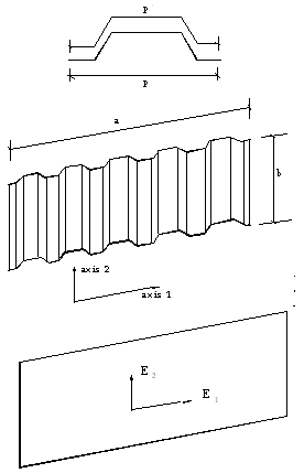 | Figure 4. Method to determine the equivalent elastic moduli |
 is expressed as:
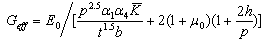 | (2) |
 | Figure 5. Finite element meshes for the cold-formed steel stud and equivalent steel sheet |
 : non-dimensional sheeting constant.
  is a function of the shape of profile and the arrangement of fasteners to the supporting frame. For a trapezoidal profile, it can be expressed in terms of the parameters
  and
and  . Meanwhile, if fastener is fixed in every trough or alternate trough,
  is different, refer to table 9.6 and table 9.7 in the Manual Stressed Skin Diaphragm Design[15].
 : non-dimensional factors, refer to table 9.1 in the Manual Stressed Skin Diaphragm Design[15]. p: pitch of corrugation (mm)h: depth of the corrugation (mm)In order to compare the influences of different equivalent shear moduli on the structural behaviour of the whole wall panel, for the panel without opening, three other assumed equivalent shear moduli, 6Geff, 2Geff and 0.5 Geff , were used in the parametric study.In the FE modelling, 4-node shell element was adopted for the equivalent sheath boards. As well, the mesh sensitivity study suggested that the element size being 100x100mm was appropriate. The material properties of the original cold-formed steel sheet were tested by Fulop[26] and E=210000Mpa, Fy=445N/mm2, Dult=20% were proposed for numerical analysis. Figure 5 shows typical meshes of the selected wall panels.
2.5. Modelling of Connections
- As aforementioned, connections are very important in a composite wall panel. 2-node spring element with non-linear mechanical property was used to simulate a connection (connector with the connected members). In the FE model, each connection was modelled by 3 spring elements, one for tension action and the other two for the shear actions. The sketch of a connection is shown in Figure 6.
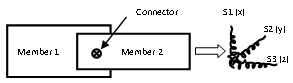 | Figure 6. Modelling of a typical connection |
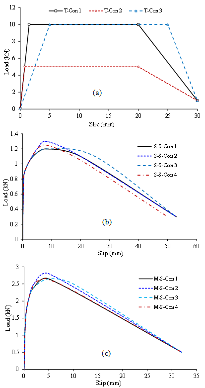 | Figure 7. Load-deformation (slip) relationships of connections: (a) connections under tension; (b) sheet/sheet connections under shear; (c) member/sheet connections under shear |
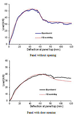 | Figure 8. Comparison of numerical prediction and experimental result |
2.6. Validation of FE model
2.6.1. Comparison of Load Capacity
- To validate the FE model described in previous sections, experimental results of two typical cold-formed steel stud wall panels (as shown in Figure 1) were selected to justify the numerical prediction. Figure 8 shows the comparison of in-plane shear load to top horizontal deflection relationships of the selected wall panels by FE prediction and experimental observation. It can be found that numerical and experimental results have a very good agreement. The comparison also indicates that using the Davies and Bryan method[15] to calculate the equivalent shear modulus of the sheeting material shows very good coincidence.
2.6.2. Comparison of Failure Modes
- The numerical modelling reproduced the failure modes and progression of selected wall panels under in-plane monotonic shear loads. With the increasing of shear load, the deformation of the wall panel began at two bottom corners (lifting up of one corner and pressing down of the other corner), then relative slip appeared at the seams of the sheets and the internal forces (axial force of spring elements) of connecters increase. The complete failure of the wall panels under in-plane shear loads was governed by the upper seam. In addition, during the increasing of the shear loads, the flange of the bottom track near to the uplifted corner wrinkles gradually and for the wall panel with an opening, the top corners of the door appeared to have larger stresses. Figure 9 shows the exaggerated deformation (failure modes) of selected wall panels with or without opening.
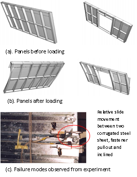 | Figure 9. The exaggerated deformation of wall panels with or without opening under in-plane monotonic load |
3. Assessment of Shear Capacity of Lightweight Steel Stud Wall Panel System
3.1. Effect of sheathing boards
- To find the effect of sheaths to the shear behaviour of wall panels, a group of material parameters as shown in Table 1and Table 2 were assumed. The varied values might represent different sheathing materials and section profiles.
|
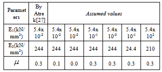
 =0.0, 0.1, 0.3. Obviously, the comparison shows that the Poisson’s ratio of sheath sheet has almost no influence on the mechanical characteristics so that in the numerical modelling, selecting
  =0.3 for the equivalent flat sheet should be reasonable.
 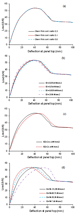 | Figure 10. Influences of sheet Poisson’s ratio (a), the sheet elastic modulus E1 (b), the sheet elastic modulus E2 (c), and the sheet shear modulus Geff (d) |
3.2. Effect of Connections
- Figure 11 (a)shows the in-plane shear load-deflection curves of the wall panel without opening but assuming different frame and tension connection models (T-Con.), little difference is found. The difference by using connections T-Con 1, 2 and 3 is not evident as shown in Figure 7(a), the initial shear stiffness, maximum shear strength and final shear strength of the whole wall panel changed slightly only (less than 5%). Figure 11(b) shows the in-plane shear load-deflection curves of the wall panel without opening but with different sheet to sheet (seam) shear connection properties (S-S-Con). The comparison shows that this kind of connection has a fair influence on the shear mechanical characteristics of the selected wall panels. With an increase of the ultimate strength of the connection, the ultimate shear load (maximum resistance) of the wall panel increased, with the increasing of the ductility of the connection, the later shear strength, ultimate top deflection and ductility of the whole wall panel increased. Figure 11(c) shows the in-plane shear load-deflection curves of the wall panel without opening but with different member to sheet shear connection model (M-S-Con) as shown in Figure 7 (c). The comparison shows that this kind of connection influences the shear mechanical characteristics of the wall panel sensitively: with an increase of the ultimate load or ductility of the connection, the ultimate shear load, final shear strength, ultimate top deflection and ductility of the wall panel increased evidently.
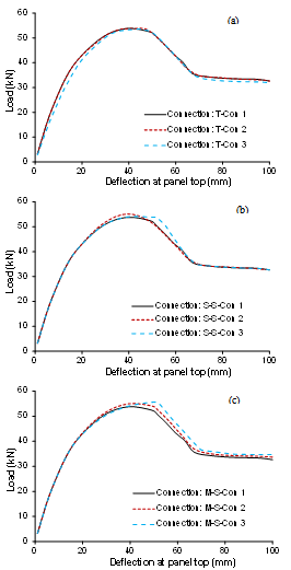 | Figure 11. Influences of the frame and tension connection (a), sheet to sheet shear connection (b), and member to sheet shear connection (c) |
3.3. Effect of Boundary Conditions
- Figure 12shows the in-plane shear load-deflection relationships of selected wall panels without opening but taking account the top restraint in the direction out of the wall plane. The comparison indicates that the difference is less than 20% for the wall panel with or without top restraint in the direction out of the plane of the wall. Obviously, the lateral restraint at wall top increased the initial in-plane shear stiffness of the whole wall panel slightly and also reduced the in-plane deflection at the wall top. But it appears the restraint did not affect the ultimate shear capacity of the wall panel. Figure 13shows the horizontal in-plane shear load-deflection relationship of the wall panel without opening but with different vertical compressive loads at the top of wall panel. The comparison indicates, if don’t take account of the buckling failure of the wall panels, the vertical loads at the wall top give little influence to the horizontal load-deflection feature of the whole wall panel.
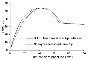 | Figure 12. Influence of top restriction on the in-plane shear load-deflection relationship of wall panel without opening |
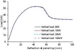 | Figure 13. Influence of vertical load at the top of panel on the in-plane shear load-deflection relationship of the wall panel without opening |
4. Conclusions
- This paper describes the numerical modelling method developed to predict the shear behaviour of typical wall-stud cold-formed steel wall panels subjected to in-plane monotonic loads. Based on the comparison and analyses, the following conclusions can be made. The shear behaviour of selected wall-stud cold-formed steel wall panels under in-plane monotonic load mainly depends on the mechanical properties of affixed sheets and connectors. Numerical simulation shows that no more than 8% of the ultimate shear resistance of the overall wall panel was carried by the bare stud frame and the whole shear capacity of the selected wall panel system was governed by the sheathing and connection strength. It appears that the equivalent tensile (compressive) elastic moduli of the sheathing sheet just slightly affect shear mechanical characteristics of the wall panel under in-plane monotonic load: with the increasing or decreasing of tensile (compressive) moduli of sheet, the initial (elastic) shear stiffness, early (hardening) shear strength of the wall panel increased or decreased slightly, while the later (softening) shear strength and ultimate top deflection decreased or increased. The changes of tensile moduli of the sheet didn’t cause noticeable effects on ultimate shear load of the wall panel. The shear elastic modulus of the sheet affects the shear behaviour of wall panel significantly: when the shear modulus of the sheet change, the shear load-deflection curve changed dramatically, but it appears the shear modulus did not influence the maximum shear capacity. The shear mechanical characteristics of the member to sheet connection (M-S-Con.) and seam connection (S-S-Con.) gave significant influence to the ultimate shear load and ductility of the wall and influenced the ultimate deflection at the top of wall panel evidently. By comparing the numerical and experimental results, simplification methods suggested by Atrek[27] and Davies[15] may be used to calculate the equivalent elastic properties and shear property of corrugated cold-formed steel sheeting respectively. The main failure mode of the selected wall panels under in-plane monotonic loads was characterized by the failure of connections of frame to sheets and sheet to sheet. Wrinkling occurred on flange of the bottom track at the corner subject to uplift. For the panel with a door opening, the top corners of the door caused larger stress concentration.
References
| [1] | Rondal, J. (2000). “Cold formed steel members and structures: General Report”, Journal of Constructional Steel Research 2000-55: pp155-158. |
| [2] | Davies, J.M. (2000). “Recent research advances in cold-formed steel structures”, Journal of Constructional Steel Research 2000-55: pp267-288. |
| [3] | Hancock, G.J. (2003). “Cold-formed steel structures”, Journal of Constructional Steel Research 2003-59: pp473-487. |
| [4] | Davies, J.M.and Leach, P.(1994a). “First-order generalized beam theory”, Journal of Constructional Steel Research 1994-31: pp187-220. |
| [5] | Davies, J.M.and Leach, P.(1994b). “Second-order generalized beam theory”, Journal of Constructional Steel Research 1994-31: pp221-241. |
| [6] | Serrette, R.L. and Pekoz, T.(1995). “Distortional buckling of thin-walled beams/panels. Part 1: Theory and Part 2: design methods”. Journal of Structural Engineering, Vol. 121, No 4, April, pp757-766, pp767-776. |
| [7] | Davies, J.M.and Jiang, C.(1996). “Design of thin-walled beams for distortional buckling”, 14th Int. Speciality Conf. On Cold-formed Sections, University of Missouri-Rolla 1996. |
| [8] | Leach, P. and Davies, J.M. (1996). “An experimental verification of the generalized beam theory applied to interactive buckling problem”. Thin-Walled Structures 1996, 25(1): pp61-79. |
| [9] | Kesti, J., and Davies, J.M.(1999). “Local and distortional buckling of thin-walled short columns”. Thin-Walled Structures 1999, 34(2): pp115-134. |
| [10] | Davies, J.M.and Dewhurst, D.W.(1997). “The shear behaviour of thin-walled cassette sections infilled by rigid insulation”, Proc. Int. Conf. On Experimental Model Research and Testing of Thin-Walled Structures, Academy of Sciences of Czech Republic, Prague, Sept., pp209-216. |
| [11] | Davies, J.M. and Fragos, A.S. (2001). “Shear strength of empty and infilled cassettes”, 3rd International Conference on Thin-Walled Structures. Krakow, Poland, June 5-7, 2001, pp3-18. |
| [12] | Fragos, A.S.(2000), “The shear buckling of metal plates and empty and filled C-shaped sections”. PhD thesis, The University of Manchester, UK, 2000. |
| [13] | Nissfolk, B. (1979). Fatigue strength of joints in sheet metal panels. Part 2: Screwed and riveted connections. Swedish Council for Building Research, Document D15: 1979. |
| [14] | Rhodes, J. (1991 edited). Design of cold formed steel members, Elsevier applied Science, London,1991. |
| [15] | Davies, J.M. and Bryan, E.R.(1982). Manual of Stressed Skin Diaphragm Design. Granda Ltd., London. |
| [16] | ECCS (1995). European Recommendations for the Application of Metal Sheeting Acting as a Diaphragm. Pub.88. European Convention for Construction Steelwork, Brussels. |
| [17] | Serrette, R.L. and Ogunfunmi, K. (1996). “Shear resistance of gypsum-sheeted light gauge steel stud walls”. Journal of Structural Engineering, ASCE, Vol. 122, No.4, April 1996. |
| [18] | Serrette, R.L., Encalada, J., Juadines, M. and Nguyen, H. (1997). “Static racking behavior of plywood, OSB, gypsum, and fibrebond walls with metal framing”. Journal of Structural Engineering, ASCE, Vol. 123, No. 8, August 1997. |
| [19] | Telue, Y. and Mahendran, M. (1998). “Behavior of cold-formed steel wall frame systems lined with plasterboard”. 2nd Int. Conf. On Thin Walled Structures, Singapore, Dec. 2-4 1998. |
| [20] | Telue, Y. and Mahendran, M. (2001). “Behavior of cold-formed steel wall frames lined with plasterboard”. Journal of Constructional Steel Research 2001-57: pp435-452. |
| [21] | Gad, E.F., Chandler, A.M., Duffield, C.F. and Stark, G. (1999). “Lateral behavior of plasterboard-clad residential steel frames”. Journal of Structural Engineering, ASCE, Vol. 125, No. 1, Jan. 1999. |
| [22] | Lee, Y.K. and Miller, T.H. (2001). “Axial strength determination for gypsum-sheathed, cold-formed steel wall stud composite panels”. Journal of Structural Engineering. ASCE Vol. 127, No.6, June 2001. |
| [23] | Fulop L. A., Dubina D., "Performance of wall-stud cold-formed shear panels under monotonic and cyclic loading: Part I: Experimental research", Thin Walled Structures, 42(2), 2004, p. 321-338. |
| [24] | Fulop L. A., Dubina D. (2004). "Performance of wall-stud cold-formed shear panels under monotonic and cyclic loading: Part II: Numerical modelling and performance analysis", Thin Walled Structures, 42(1), 2004, p. 339-349. |
| [25] | Fulop, L.A., Dubina, D. (2006). "Design Criteria for Seam and Sheeting-to-Framing in Colf-Formed Steel Shear Panels", Journal of Structural Engineering, 2006, vol. 132, no. 4, p. 1-9. |
| [26] | Fulop, L. A. (2003). “Contributions to the optimization of structural systems for one family houses with steel structures”. PhD thesis, Politehnica University of Timisoara , Romania, 2003. |
| [27] | Atrek, E. and Nilson, A.H.(1980). “Nonlinear Analysis on Cold-formed Steel Shear Diaphragms”, Journal of The Structural Division, ASCE, Vol. 106, No. ST3, March, 1980. |
| [28] | Fulop, L. and Dubina, D. (2001) “Performance of Shear Wall Systems in Seismic Resistant Steel Building”, Report 2001, Politehnica University of Timisoara, Romania |
| [29] | Fulop, L. and Dubina, D. (2001) “Performance of Shear Wall Systems in Seismic Resistant Steel Building”, Report 2001, Politehnica |