Elsa Eka Putri, N. S.V Kameswara Rao, M. A. Mannan
Civil Engineering, Universiti Malaysia Sabah, Kota Kinabalu, Sabah, 88999, Malaysia
Correspondence to: Elsa Eka Putri, Civil Engineering, Universiti Malaysia Sabah, Kota Kinabalu, Sabah, 88999, Malaysia.
| Email: |  |
Copyright © 2012 Scientific & Academic Publishing. All Rights Reserved.
Abstract
This paper presents the procedure of evaluation of the modulus of elasticity (E) and the modulus of subgrade reaction (ks) value based on the California Bearing Ratio (CBR) tests and FEM analysis. The pressure-displacement response of the soil in the CBR mould is simulated using Cosmosworks FEM model where the soil, the load plunger, and the steel mould of CBR are represented. The correlation of Modulus of Elasticity (E) with California Bearing Ratio (CBR) is developed based on the elastic properties of the soil sample. Furthermore, the correlation between E and CBR is proposed. Using the E values, modulus of subgrade reaction can be calculated and vice versa as well. Thus CBR test is expected to simplify the effort in determination of the modulus of subgrade reaction which is used in Foundation design, soil structure interaction, design of highway formations etc.
Keywords:
California Bearing Ratio (CBR), Plate Load Test (PLT), Modulus of Elasticity (E), Modulus of Subgrade Reaction (ks), CosmosWorks FEM
Cite this paper: Elsa Eka Putri, N. S.V Kameswara Rao, M. A. Mannan, Evaluation of Modulus of Elasticity and Modulus of Subgrade Reaction of Soils Using CBR Test, Journal of Civil Engineering Research, Vol. 2 No. 1, 2012, pp. 34-40. doi: 10.5923/j.jce.20120201.05.
1. Introduction
In highway formations the subgrade layer, where acts as a pavement foundation should be well designed. To evaluate the subgrade strength is important during construction and design stage. The California Bearing Ratio (CBR) test is commonly used to determine the suitability of a soil as a subgrade or subbase for highway and runway design and construction. Field plate load test is commonly used to predict the deformations and failure characteristics of the soil/subgrade and modulus of subgrade reaction (ks). Modulus of subgrade reaction (ks) is used in foundation design, soil-structure interaction studies and design of highway pavement (flexible and rigid pavements). One of the parameters obtained from the field plate load test is the spring constant/ modulus of subgrade reaction, ks-value. The ks-value is used as a primary input in pavement design models, and is based on Minnesota Department of Transport (MnDot) pavement design. It can be measured using a field plate load test conducted on top of the subgrade (Kameswara Rao, 2000; MnDoT, 2007). However, this test is costly to perform besides being time consuming. Also it is difficult to conduct a plate load test at depths beyond 1 or 2 m below Ground Level (GL).As presented in Figure 1, the CBR test procedure issomewhat similar to the plate load test. As the load is imposed on the sample soil, the deflection will occur. The plate is placed at the proposed level of the foundation and is subjected to incremental loading. The size of the plate can be 300 mm to 760 mm in diameter and the shape is square, rectangular, or circular (Jones, 1997; Moayed and Janbaz, 2009).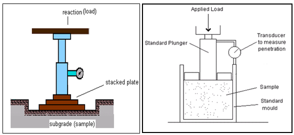 | Figure 1. Figure of CBR and PLT set up |
The CBR test can also be used to get the curve of the load–settlement of the soil in the field which is more or less similar to the plate load test objective. By this idea, the value of ks can also be obtained from the CBR test as described below. In this investigation, the correlation of CBR versus E then CBR versus ks are developed to bridge the gap which is much needed to integrate the engineering behaviour of these two hitherto uncorrelated tests, though concerned with the same subgrade properties needed for engineering design of foundations and pavements. This correlation will also facilitate integrating, complimenting and improving the design procedures based on CBR value and ks used in highway engineering as well as foundation engineering.
2. Literature Review
The modulus of subgrade reaction, ks (also referred to as Coefficient of Elastic Uniform Compression, Cu) is a relationship between soil pressure and deflection which is proportional to its vertical displacement as idealized in Winkler’s soil model (Hetenyi, 1946; Jones, 1997). It can also be defined as the ratio of uniform pressure imposed on the soil to the elastic part of the settlement (Kameswara Rao, 2000).Very little work has been reported for the correlation between modulus of subgrade reaction (ks) and CBR test though the mechanism of deformation is similar. Terzaghi (1955) studied the various parameters of the plate load test using a circular plate of 760 mm diameter and thickness of 16 mm. He also proposed an empirical correlation between CBR and E as shown in Figure 2 (Jones, 1997). Figure 2 also presents the empirical correlations between modulus of elasticity, E with CBR that have been worked out by Heukelom and Klomp (1962), NAASRA (1950) and Powell, Potter, Mayhew and Nunn (1984).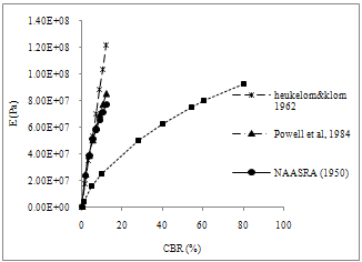 | Figure 2. California Bearing Ratio versus Modulus of Elasticity |
Heukelom and Klomp (1962) studied the correlation of CBR with E and proposed on empirical relationship as,  | (1) |
This correlation is only for fine grained non expansive soils with a soaked CBR < 100% (AASHTO, 1993). Moreover, Powell et. al (1984) proposed a correlation of the CBR with E as,  | (2) |
Thus, the correlation between E and CBR developed by NAASRA (1950) has been divided into two parts.  | (3) |
 | (4) |
These correlations between E and CBR were developed using empirical methods which are validated using other sets of tests data based on the experimental tests in the laboratory.In order to develop the procedure to correlate the CBR result with the PLT result, the finite element method is used to model the CBR test with input parameter obtained from the laboratory testing. It offers a rational approach to develop the correlation of CBR versus E. These values are subsequently used for evaluating the modulus of subgrade reaction, thus providing an easier way for analysis of soil structure interaction and pavements.
3. Methodology
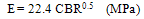
The CBR test is modelled using FEM to work out the pressure response relationship. The finite element model was assembled using the Cosmoswork SolidWork 2005. The CBR mould model in Cosmosworks consists of base plate, cylinder mould, and load plunger and those are specified as steel in the input. The structural properties of the soil subgrade were required as input data. These are the density, modulus of elasticity and Poisson’s ratio. Poisson’s ratio is a property of elastic materials assumed to be in between of 0.2 to 0.4. The Poisson’s ratio of zero is usually used for dry soil and the value of 0.5 is usually used for saturated soils. It is usually assumed due to the difficulties in its determination in the laboratory or in the field, while recognizing that elastic responses of the medium are not very sensitive to changes in the value of Poisson’s ratio (Bowles, 1984). Thus, it does not significantly affect the elastic response of the soil though it can vary from 0 to 0.5 (Harr, 1966, Kameswara Rao, 2000).Finite element analysis was carried out with a range of value of E (modulus of elasticity) chosen from 1.00E+6 Pa until 1.00E+7 Pa for finding the load deflection curves. From these, the load penetration of 2.5mm of the CBR plunger (of 50.8 mm diameter) is chosen for the determination of CBR value (BS 1377:1990).Finite element analysis can also be used to determine the response of vertically loaded plunger in layered elastic media. It is noted that the FEM analysis gives different values of deflection at the centre of the CBR plunger and at the edge though the mould is practically very rigid. In order to relate the finite element result with the CBR test in the laboratory, the elastic analysis has been corrected to that corresponding to rigid analysis using the analytical results given by Tsytovich (Harr, 1966 results). Hence, the central deflection of the plunger is corrected to obtain the corresponding deflection of the rigid plunger using the results of Tsytovich (Harr, 1966). Thus the deflection at the centre of circular shaped loaded area of the CBR plunger should be multiplied by the influence factor K = 0.79 (=π/4) as per Tsytovich, to get the corresponding value of the deflection of the rigid plunger of the CBR mould transferring the load to the soil. The procedure of correlation CBR versus E then CBR versus Plate Load test is developed as presented in Figure 3. | Figure 3. Flow chart of the procedure to predict the PLT result |
4. Result and Discussion
4.1. CBR Parameter
The result from a typical CBR test is presented in Figure 4. It shows the larger deflection at higher loads on the soil sample. This trend is more or less similar to the result of plate load test which is usually performed to get the graph between mean bearing pressures versus mean settlement.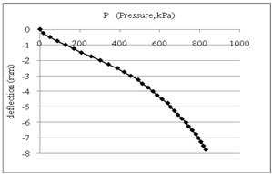 | Figure 4. Result from CBR test |
The deflection due to application of load plunger (CBR mould) in Figure 4, represents the response of soil subgrade structure to the applied load in a rigidly confined CBR mould. Thus as per BS 1377-1990, the CBR value from this data is 5.5%.
4.2. Finite Element Method
It can be seen in Figure 4 where the CBR mould model in CosmosWorks Finite Element Model. It consists of base plate, cylinder mould, and load plunger and those are specified as steel in the input as can be seen on Figure 4(a) and 4(b), where the condition of CBR mould in the Cosmoswork model and the solid mesh condition of the model respectively. 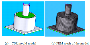 | Figure 5. CBR mould in CosmosWorks |
The result of the relationships between load and deflection of the subgrade soil with various E values are presented in Figure 6.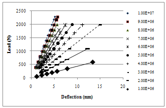 | Figure 6. Relationship between load and deflection of the soil subgrade using FEM |
It can be shown in Figure 6; the deflection is lower for high value of modulus of elasticity at similar value of load. The corresponding values of load are determined at 2.5 mm deflection for various values of E. However, correlation can also be developed with the CBR value corresponding to 5 mm deflection of the plunger to get a similar figure as in Figure 5 following the same procedure as outlined below. Then, the CBR value was predicted at prescribed displacement of 2.5 mm of the plunger (BS 1377-1990). The results shown in Figure 6, however, are for homogeneous elastic media subjected to CBR test. Thus, it needs to be corrected with the influence factor, K in order to get the corresponding value of the deflection of a rigid body transferring the load to the soil using the analysis of Tsytovich as discussed in section 3.
4.3. Correlation of CBR versus E
To get the correlation of CBR versus E, the results of load versus deflection in Figure 4 are first adjusted by multiplying with the correction factor of 0.79 and then calculating the load for deflection at 2.5 mm for CBR tests. Moreover, at the specified load the value of E will be determined. Thus, the correlation of CBR vs. E will be derived. For example, for E = 3.00E+06 the load at 2.5 mm deflection is 939.2 N (Figure 5) and the CBR value based on BS 1377-1990 is 7.1%.The correlations of CBR vs. E are presented in Figure 7 after correction for rigid plunger deflection from the results presented in Figure 6 for various values of E of soil. The correlations developed by others are also presented for comparison.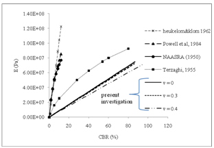 | Figure 7. CBR versus E obtained from the FEM with various of Poisson’s ratio |
The correlation result from present study is close to the result from Terzaghi (1955) while the correlation made by Heukelom and Klomp (1962), NAASRA (1950) and Powell, Potter, Mayhew and Nunn (1984) differ considerably probably due to their empirical nature.From Figure 7, the correlations between E and CBR from the present investigation are as follows, 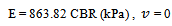 | (6) |
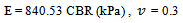 | (6) |
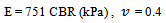 | (7) |
For example, the CBR value of the soil tested in laboratory is equal to 3%, thus the value of E will be 2591.46 kPa, 2521.59 kPa and 2253 kPa for Poisson’s ratio equal to 0, 0.3 and 0.4 respectively. The interpolation may be used for other intermediate values of the Poisson’s ratio of the soil. An average value of E = 810 CBR (kPa) may be adopted in the absence of any data on Poisson’s ratio.It may be noted that the E value of the soil thus obtained using FEM takes into account the rigid boundary condition of the CBR mould.
5. CBR Test for the Prediction of the Plate Load Test Results
Plate load test is needed to find the load-settlement curve that can determine the bearing capacity and settlement of the soil and subsequently to calculate the ks (modulus of subgrade reaction) value as the ratio of the pressure imposed to the settlement on the soil. The plate is placed at the proposed level of the foundation and is subjected to incremental loading. The plate can be 300 mm to 760 mm in diameter and the shape of plate can be square, rectangular or circle (Jones, 1997; Moayed and Janbaz, 2009).The CBR test can also be used to get the curve of load-settlement of the soil in the field which is more or less similar to the plate load test objective. By this idea, the value of ks can also be obtained from the CBR test, as describe below.
5.1. Modulus of Subgrade Reaction, ks
The CBR value of the clayey sand soil describe in figure 3 gives CBR value equal to 5.5%. By means of the developed correlation, if the Poisson’s ratio of the soil is 0.4, it gives the modulus of elasticity, E = 751 CBR (kPa) as in Figure 6. Thus the value of E = 4751.01 kPa. Then modulus of subgrade reaction, ks, can be expressed using the following expression, from theory of elasticity solution for a rigid plate on a semi-infinite elastic soil medium subjected to a concentrated load (Timoshenko and Goodier, 1951; Harr, 1966; Kameswara Rao, 2000) as,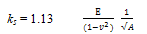 | (8) |
where: E = Modulus of Elasticity v = Poisson’s ratio A = area of the plate or CBR plungerPresuming that ks is to be obtained from a plate load test, with the area of the plate and Poisson’s ratio value as 20.268 cm2 and 0.4 respectively the modulus of subgrade reaction, ks for clayey sand soil can be computed as 123423.07 kN/m3.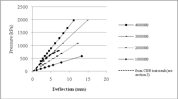 | Figure 8. Pressure-Deflection results from FEM with various value of E (Pa) |
The graph from CBR test result can also directly be used to determine the E value. As can be seen in Figure 8, the result from CBR test in Figure 4 is inserted in the Figure 6 after changing the abscissa as a pressure in kPa.Hence, the modulus of elasticity, E, of clayey sand soil at the 2.5 mm deflection is around 3900 kPa. Using Equation (8), the value of ks is 116535.52 kN/m3. Thus the value of ks for every size, shape and rigidity of plate can be computed knowing the value of E of the soil, which can be obtained from the CBR using equation (8).
5.2. Predicting Plate Load Test Response
Plate load test response prediction under elastic conditions from the CBR test result can be carried out using Equation (9). In view of the similarity of the test procedures of CBR test and field plate load test (except for the boundary restraints in the CBR test), the CBR test can be used as a model to predict the field plate load test after converting the result of the confined boundary of CBR test to that of a responses of the CBR plunger (model plate) on a semi-infinite elastic medium. Then the field plate load test can be estimated using the dimensional similarity of the CBR plunger and field plate as follows. However, the method may be cautiously applied as it is applicable for linear elastic or close to linear elastic behaviour of the soil media.a. The relationship of the CBR test results with the field plate load test result is obtained as follows;For rigid circular shaped load acting on the semi-infinite elastic soil medium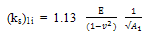 | (9) |
 | (10) |
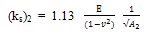
b. The ratio of CBR and plate load deflections from Equation (9) and Equation (10), is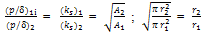 | (11) |
(for circular plate)where, A1, r1, δ1i = for the area, radius and deflection of the CBR plunger.A2, r2, δ2 = for the area, radius and deflection of the plate from plate load test.c. For the same value of p1=p2, we get from Equation (11) | (12) |
Equation (12) is the correlation of the deflection for the field plate over the deflection for the CBR plunger, which is equal to the ratio of the radius of field plate to the radius of the CBR plunger.d. The  corresponding to the CBR plunger deflection on a semi infinite soil medium can be calculated as follows.From the result of CBR test in Figure 4, for a particular value of p get the corresponding value of δ. From these values of p (pressure) and P (load) ( P = p . area of the plunger), get the value of E of the soil from Figure 8.Then,
  | (13) |
, can be calculated, knowing p for the pressure and A, being the area of the CBR plunger (50.8 mm diameter) from the above Equation (13).Hence, from the equation (12), the deflection for the field plate load test, can be predicted as, | (14) |
It may be noted that δ1 = the deflection of the plunger in the CBR mould (load on confined soil medium), and = the deflection of the CBR plunger on a semi-infinite elastic soil medium. The steps for the calculation of prediction of the plate load test results for v= 0, 0.3 and 0.4 are given in the appendix. It may also be noted that CBR values can also be predicted from the plate load test results by inverting the above steps.
6. Conclusions
(a) The correlation between E and CBR gives several advantages that can facilitate to obtain the modulus of subgrade reaction, ks used for designing the pavement thickness. (b) The correlation of ks vs. CBR can be used to predict the results of field plate load test and other elastic analyses. (c) More rational approaches using E and v such as threshold stress approach of design (Shahu, 2000) can be developed for practical application. This correlation will help in improving the design of highway formations using the empirical parameters such as CBR value and analysis based methods which adopt values of E or v , threshold stress, liquefaction etc.(d) CBR test which is very easy to conduct in the lab using the undisturbed soil samples from the site can be used to predict the behavior of soils at any depth. The modulus of subgrade reaction, ks which is otherwise difficult to determine at depths more than 1 or 2 m below the Ground Level, can also be assessed. (e) Also, by reversing the steps presented in section 5, the CBR value can be predicted using the results of the field plate load test.Appendix; Prediction of Plate Load Test (PLT) deflections from CBR test ResultPrediction of the PLT response for plate diameter = 760 mm from CBR test result which having an area of the CBR plunger,  . The result from the CBR test as presented in the Figure 2 is used to predict the field PLT response. The procedures are as follows,Poisson’s ratio, v = 0.4Determination of the deflection for the semi infinite soil medium from the CBR test result,
  .1. At deflection,
  = 2.5 mm from the CBR test result in figure 2, the pressure, p = 400 kPa. Then from Figure 4, the value of modulus of elasticity for this soil, E is equal to 3900 kPa and by means of Figure 5 which has been developed a correlation of CBR vs. E, obtained the CBR value equal to 5.2%. With this E by means of Equation (14), the
  can been calculated. Hence,
  = 3.43 mm.2. Then to predict the value of
 , the Equation (15) is used,
  3.43 mm = 51.31 mmPoisson’s ratio, v = 0.3Determination of the deflection for the semi infinite soil medium from the CBR test result,
  .At deflection,
  = 2.5 mm from the CBR test result in figure 2, the pressure, p = 400 kPa. Then from Figure 5, the value of modulus of elasticity for this soil E is equal to 3900 kPa and by means of Figure 5, the CBR value equal to 4.7%. With this E, the
  can been calculated. Hence,
  = 3.6255 mm.Then to predict the value of
 , the Equation (15) is used,
  . 3.6255 mm = 54.24 mmPoisson’s ratio, v = 0Determination of the deflection for the semi infinite soil medium from the CBR test result,
  .1. Use the similar procedure with (i) and (ii), the CBR value equal to 4.5% for Poisson’s ratio, v = 0. Then the deflection for the semi infinite soil medium from CBR test,
  can been calculated use the equation (13). Hence,
  = 3.794 mm.2. Then to predict the value of
 , the Equation (15) is used,
  . 3.794 mm = 56.77 mmThus, the deflection of a CBR plunger on a semi-infinite elastic soil medium at p = 400 kPa is 3.43 mm, 3.63 mm and 3.79 mm. The predicted deflection of the field plate load test of soil sample in the field will be at 51.31 mm, 54.24 mm, 56.77 mm for Poisson’s ratio of 0.4, 0.3 and 0 respectively.Results of the pressure-deflection prediction of the field PLT from the above computation.The results are presented in Figure 9 for all the pressure-deflection data from a single CBR test result (shown in Figure 4) for Poisson’s ratio, v equal to 0, 0.3 and 0.4 after following the calculation in step (i) to (iii).
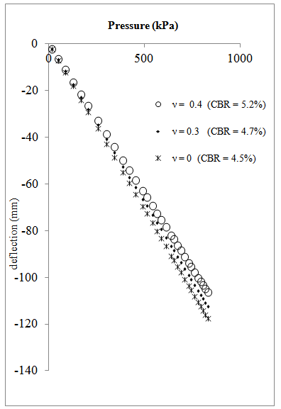 | Figure 9. Prediction of field plate load test response for d = 760 mm (v = 0, v = 0.3, v = 0.4), E = 3900 kPa |
ACKNOWLEDGEMENTS
This project is sponsored by the FRGS (Fundamental Research Grant Scheme) Universiti Malaysia Sabah no. FRG0074-TK-1-2006 and FRG 174-TK-2008.
References
| [1] | Bowles, J.E. 1997. Foundation Analysis and Design. 5th Edn., McGraw-Hill, New York, |
| [2] | BS 1377-4:1990. Method of test for soils for civil engineering purposes |
| [3] | Carpenter,W.A., Ozyildirim, H. C and Vaswani, N. K. 1975. Determining elastic moduli of materials in pavement systems by surface deflection data, a feasibility study. Virginia Highway & Transportation Research Council. |
| [4] | Croney, D, & Croney, P. (1991). The design and performance of road pavements. (2nd edition) Mc Graw-Hill Book Company. |
| [5] | Barkan, D.D. 1962. Dynamics of bases and foundations. McGraw-Hill, New York, NY. |
| [6] | Jones, G., 1997. Analysis of beams an elastic foundation. Thomas Telford, United Kingdom. |
| [7] | AASHTO. 2003. Guidelines for pavement design, Virginia DoT-Materials Division Pavement Design And Evaluation Section, Revised – May 2003 |
| [8] | Harr, M. E. 1966. Foundations of theoretical soil mechanics. McGraw-Hill, New York. |
| [9] | Helwany, B., and Shih, S. 1998. Creep and stress relaxation of geotextile-reinforced soils. Geosynthetics International, 5(4), 425-434. |
| [10] | Hetenyi, M. 1946. Beams on elastic foundation. University of Michigan Press, Ann Arbor. |
| [11] | Huang, Y. H. 1993. Pavement analysis and design. Prentice Hall, New Jersey |
| [12] | Kameswara Rao, N.S.V. 2000. Dynamic soil tests and applications. A. H. Wheeler & Co. Ltd, New Delhi, First Edition. |
| [13] | Liu, C., and Evett, J.B. 2005. Soils and Foundation. S1 Edition, Prentice-Hall Inc. |
| [14] | MnDoT. 2007. Pavement Manual. Minnesota Department of Transport, Chapter 3. |
| [15] | Moayed, R.Z., and M. Janbaz. 2009. Effective parameters on modulus of subgrade reaction in clayey soils. J. Applied Sci., 9: 4006-4012. |
| [16] | NCHRP. 2003. Guide for mechanistic-empirical design of new and rehabilitated pavement structures. National Cooperative Highway Research Program Transportation Research Board National Research Council, Illinois 61820 |
| [17] | Odemark, N. 1949. Investigations as to the elastic properties of soils design of pavements according to the theory of elasticity. Stockholm, Sweden. |
| [18] | Papagiannakis, A. T., and Masad, E. A. 2008. Pavement design and materials, John Wiley & Sons Inc. |
| [19] | Powell, W.D., Potter, J.F., Mayhew, H.C., and Nunn, M.E. 1984. The structural design of bituminous roads. TRRL Report LR 1132,62pp. |
| [20] | Shahu, J. T., Yudhbir, Kameswara Rao, N.S.V. 2000. A rational method for design of railroad track foundation, soils and foundations. Japanese Geotechnical Society, Soil and Foundation vol.40. |
| [21] | Sukumaran, B., Kyatham, V., Shah, A., and Sheth, D. 2002. Suitability of using California Bearing Ratio to predict resilient modulus, presented on FAA Airport Technology Transfer Conference 05/2002. |
| [22] | Thompson, M.R., and Robnett, Q.L. 1979. Resilient properties of subgrade soils. Journal of Transportation Engineering, ASCE, Vol. 105, No. 1, pp. 71-89. |
| [23] | Timoshenko, S., and Goodier, J.N. 1951. Theory of Elasticity. Mc Graw-Hill, Book Company Inc, New York, US |
 Abstract
 Reference
 Full-Text PDF
 Full-text HTML