Parvez Alam 1, Martin Ansell 2
1Centre for Functional Materials, Abo Akademi University, Turku, Finland
2Department of Mechanical Engineering, University of Bath, Bath, UK
Correspondence to: Parvez Alam , Centre for Functional Materials, Abo Akademi University, Turku, Finland.
| Email: |  |
Copyright © 2012 Scientific & Academic Publishing. All Rights Reserved.
Abstract
This paper addresses the function of nailing density on the flexural properties of vertically laminated steel-timber flitch beams. Increasing the nailing density slightly improves the flexural stiffness but concurrently causes a clear reduction in flexural strength. Stresses in the mechanical fasteners are primarily localised to the area in contact with the steel plate. Nails placed centrally play no role in resisting normal tensile-compressive stresses during flexion however; they reduce the onset of buckling and provide extra resistance in vertical shear. All composites buckle on the compressive face however higher density nailing series buckle less prominently. Shot fired nailing is a fast and effective method for joining components of structural composites.
Keywords:
Timber, Steel, Flitch, Nailing Density, Pattern, Strength, Stiffness
Cite this paper:
Parvez Alam , Martin Ansell , "The Effects of Varying Nailing Density upon the Flexural Properties of Flitch Beams", Journal of Civil Engineering Research, Vol. 2 No. 1, 2012, pp. 7-13. doi: 10.5923/j.jce.20120201.02.
1. Introduction
Timber can be effectively upgraded for strength and stiffness through the application of reinforcement. Laminating timber is an effective means for upgrading or repair and employs strong and stiff reinforcing materials. Steel is a relatively cheap, high-modulus and easily available material that can be used to reinforce timber. Timber-steel flitch beams as defined in[1] are traditional structural composites that have experienced a decline in use most probably due to both; arduous pre-drilling and bolting methods and a rise in interest in adhesive joining methods. This said one modern large scale example where the timber-steel flitch assembly is used is the Nagano Olympic Memorial Arena located in [2]. Flitches are vertical laminates or inserts to timber, sometimes spanning the entire depth of a beam and other times occupying a part of the beam depth. Comparing vertical and horizontal metallic laminates in timber beams, Sliker[3] reported that the dominating failure modes differ. Beams with horizontal laminates fail through horizontal shear, while vertically laminated beams tend to fracture on the tensile face of the beam. Nailed steel-timber flitch beams, as reported in[4], yield significant improvement in the strength and stiffness of untreated beams. Creosote treated beams however improved the strength and stiffness of the beams by less than half that for untreated equivalents. More durable timber composites necessitate treatment and the preservative effect of creosote compensates to some effect, for the lowered stiffness and strength benefits. Coleman and Hurst[5] considered the effects of nailing density on the flexural properties of flitch beams. Their results were inconclusive and the flexural properties of the flitch beams did not reveal any correlation between the flexural properties and the number of nails used to connect the composite elements. Coleman and Hurst however, believed this to be a consequence of having low variability in the number of nails used and indeed, they felt that the numbers of nails used were high enough to develop the fill strength of the steel reinforcement. Borgin et al.[6] pulled steel flitch inserts closer to the furthermost fibres of the timber, in one case on only the compressive face of the timber and in another case on both tensile and compressive faces. The motivation for reinforcing only the compression face lay in that wood is in fact weaker in compression than in tension. Timber failure was hence taken by Borgin and co-workers, to be determined by compressive failure of the wood and was indeed the logic behind locating all of the steel on the upper face for one of the samples. Beams reinforced on the upper face were found to yield lower values for flexural stiffness and exhibited higher centre point deflections as compared to beams that were reinforced on both faces. Beams reinforced on the upper face however, also resisted higher loads until failure. By reinforcing both the tensile and compressive faces, the higher stiffness material is pushed farther from the axis of neutrality which yields a considerable increase in the second area moment of the composite beam. Reinforcing on one face with a deeper laminate brings the reinforcement centroid closer to the beam’s neutral axis and will consequently possess a second area moment that is lower than beams reinforced on both faces. Borgin and co-workers showed that, with respect to strength, there is a clear advantage in reinforcing timber only in compression. However, there was no benefit for the ductility of the composite beam. Adequate reinforcement of only the tensile face can exploit the ductile plastic yield behaviour of timber in compression without permitting sudden tensile fracture[7]. The result is that the overall ductility of reinforced timber composites are significantly improved, which is a much- preferred mode of failure. Hoyle[8] also vertically laminated only the top and bottom faces of timber beams with steel. In their research, toothed steel plates were connected mechanically by pressing the teeth protruding from the steel plates into two surrounding timber members. Hoyle found that beams taken to failure under conditions of static flexural loading experienced buckling of the steel plate on the compressive side of the beam, which was not so marked so as to cause the timber members to separate. Long slender reinforcements are geometrically unstable when subjected to compressive loads. The intimacy, strength and stability of connection between composite elements are therefore factors paramount in preventing unwanted buckling, which may indeed lead to early failure and beam instability. The objectives of this paper are to ascertain the effects of altering nailing density on the flexural properties of the composite beam. That is, the optimum number of nails used to fasten the composite, as this is still an area of flitch beam technology that remains somewhat unclear[5]. It is in the interest of both optimising the strength of composite beams and the cost of firing in nails to determine the outcome of increasing the nailing density. Whether the reinforcement truly serves any function in the region of the beam’s neutral axis is a thought worthy of note, as ineffectual reinforcement is costly, weighty and unnecessary. Jones[9] demonstrated that reinforcing rods are almost insignificant in their contribution to strength and stiffness close to the axis of neutrality. Although a flitch plate, unlike steel rods, is a continuous and uninterrupted element, there is no apparently obvious reason why Jones’ finding should not apply. The research employs a shot-fired nailing technique that circumvents the arduous task of pre-drilling and bolting or nailing. Rather, bainitically hardened steel nails are shot through steel and wood elements to create the mechanical connection.
2. Materials and Manufacture of Composite Beams
Steel-timber composite flitch beams were manufactured from Kerto S laminated veneer lumber (LVL) and mild steel plate. The steel plates were laminated vertically on the timber. The dimensions of the composite elements are presented in Table 1. The LVL was cut slightly deeper than the steel in order to avoid possible geometric instability during loading under the rollers in bending.Two-piece (steel-wood) geometries, doubled up were manufactured so that the nails could be applied with increased precision into the steel plates. Has a lower variability in mechanical properties as compared with low-grade softwood, which is why it was chosen over spruce or timber. Each composite beam comprised a single beam of LVL connected to a single steel plate but the steel-LVL composite beams were tested in pairs. The composite elements were connected by shot fired nailing and 50mm long bainitically hardened nails were used. These nails were shot through the steel plate into the LVL using five different nailing densities (labelled series A-E). These were based upon minimum nail spacing guidance for un-drilled nailing as provided in Table 6.3.1.2 of EC5, DD ENV1995-1-1 (1994)[10]. The code rules were minimally modified so they would fit into the dimensions of the beams and furthermore, did not incorporate the suggested modification factor of 0.7 for connecting steel to timber so as to account for the potential damage that may occur during shot firing. The spacing guidance from Table 6.3.1.2, EC5, provides separate values for timber with a density below 420kgm-3 and between 420-500kgm-3. The higher value of the two was used in each case. Table 2 gives the code guidance minimum nailing distances, the subsequently modified distances used in testing and the maximum spacing distances used in testing. | Table 1. Dimensional properties of composite elements making up the LVL-steel beams |
| | Material | Length/mm | Depth/mm | Thickness/mm | Diameter/mm | No. used per beam | | Mild steel | 1900 | 100 | 6 | - | 1 | | Kerto S LVL | 1900 | 110 | 51 | - | 1 | | Nails | 50 | - | - | 3.6 | Variable |
|
|
| Table 2. Eurocode 5 guidance for minimum nailing distances for un-drilled timber of a density between 420-500kgm-3 where d signifies the nail diameter. The distances based upon this guidance are slightly different from the minimum distances used, which were modified to fit the beam dimensions, and the maximum distances used during testing were used in the lowest nailing series |
| | Spacing | EC5 guidance | Distance based on EC5 guidance/mm | Modified minimum distances/mm | Maximum distances used/mm | | Between nails // to grain | 15d | 54 | 60 | 240 | | Between rows of nails ┴ to grain | 5d | 18 | 25 | 50 | | Distance to unloaded end // to grain | 15d | 54 | 50 | 50 | | Distance to unloaded edge ┴ to grain | 7d | 25.2 | 25 | 25 |
|
|
To ensure greater nailing precision, the nails were shot from the steel into the wood, since the position of each of the composite members relative to the other can be clearly seen. Series A comprised the lowest number of nails, and the nailing was consecutively increased through series B, C, D and E respectively up to the highest allowable nailing density (93 nails) found in series E. Table 3 provides information regarding the numbers of nails used in each series. Nailing patterns were arranged so as to maximise the symmetry of the nailing points through the depth of the beam in each series, Figure 1.| Table 3. Number of nails used for each nailing series and the resulting nailing densities |
| | Beam series | No. nails used per beam | Nailing density/% [assuming shortest nail spacing ≡ 100% ≡ 93 nails] | | A | 16 | 17 | | B | 32 | 33 | | C | 47 | 50 | | D | 77 | 83 | | E | 93 | 100 |
|
|
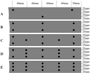 | Figure 1. Series A-E nailing patterns |
3. Test Conditions and Specifications
The composite beams were tested in pairs under four- point bending in accordance with[11]. The cross section arrangement of the beam pair arrangement is shown in Figure 2 (a). Loading this beam pair arrangement could easily lead to geometric instability. Therefore, 10mm thick spacers were placed between the beams and enveloping stabiliser plates were applied to the beam pair in order to avoid twisting, Figure 2 (b). The spacers were made of plywood and attached to the beams using a firm tape. As the spacers were short in length, comparatively weak and simply taped on, it is unlikely that they bear any contribution to strength or stiffness. The function of the spacers was simply to prevent the nail heads from hooking onto one another during testing when the stabiliser plates, each comprising a tightened steel sheet, were attached. Equations 1 and 2 represent the composite second mo-ment of area, Ic, and the elastic composite section modulus, Wc, respectively. Wc is an approximated value since it as-sumes that the global composite distance from the beam centroid to the outermost fibres is a linear average of that for the mild steel and the LVL. | (1) |
 | (2) |
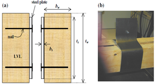 | Figure 2. Cross section schematic of the beam pair showing the arrangement of composite elements and the nailing direction. The depth of the wood and the steel is represented by tw and ts respectively. The width of the wood and the steel is represented by bw and bs respectively |
Linear variable differential transformer (LVDT) displacement transducers were used to monitor the centre point deflection on each beam in the beam pair. Force was applied at a rate of 2mm.min-1. Figure 3 shows a schematic of the test set-up. The moisture content of the beams at the time of testing was approximately 12%. The beams were tested in service class 2 conditions.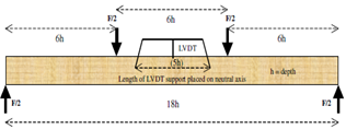 | Figure 3. Four-point bend test set-up taking advise from[11] |
4. Finite Element Models
4.1. Building the Models
3D linear elastic finite element models were developed to understand better the stress and strain profiles in the nails relative to their positions in the composite.Beam segments were modelled from the centre point of a representative beam from each beam pair series, taking advantage of symmetry in both the wood and the steel as well as the obvious symmetry in the nailing patterns. Figure 4 shows the segments modelled for each series.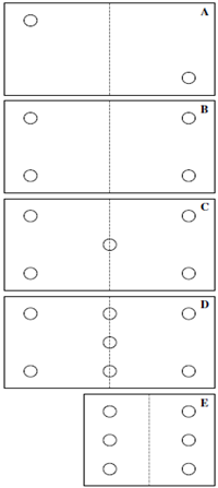 | Figure 4. Front view of beam sections modelled for each series as shown on the right side of each dashed line. The section on the left hand side signifies the nailing pattern symmetry upon which the section sizes were chosen. Inverse symmetry exists for series A |
The dimensions of the modelled composite components are provided in Table 4.| Table 4. Dimensions of the composite components for each model in each series (see Figure 4.) |
| | A | B | C | D | E | | Nails | Length/mm | 50 | 50 | 50 | 50 | 50 | | Diameter/mm | 3.6 | 3.6 | 3.6 | 3.6 | 3.6 | | LVL | Length/mm | 100 | 100 | 100 | 100 | 60 | | Depth/mm | 110 | 110 | 110 | 110 | 110 | | Thickness/mm | 51 | 51 | 51 | 51 | 51 | | Steel plate | Length/mm | 100 | 100 | 100 | 100 | 60 | | Depth/mm | 100 | 100 | 100 | 100 | 100 | | Thickness/mm | 6 | 6 | 6 | 6 | 6 |
|
|
4.2. Discretisation of Composite Components
Higher order ten-node three-dimensional structural solid elements were chosen to mesh all the solid bodies. The element is suitable for meshing complex and irregular shapes. The element has three degrees of freedom at each node in the direction of the three principal axes. A 1mm element edge length was applied to the nails, Figure 5.After meshing the nails, three element divisions were allocated to every element edge length for the regions of the steel plate and LVL directly in contact with the meshed nails. Three element divisions were also allocated to the edges of the steel plate and the LVL, furthermost from the contact region with the nails. The resultant mesh density is high in the regions where the LVL and the steel plate contact the nails. The mesh density consecutively decreases with increasing distance from the nails. Further reduction in the mesh density was possible through splitting the LVL and steel plate members along the vertical axis. This ensured a low mesh density in regions where the nails were absent and which were expected to have less importance with regard to the introduction of localised stresses in the LVL and steel plate. Figure 6 provides an example of a fully discretised model, in this case, a series D model.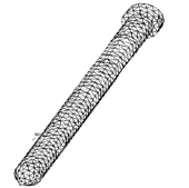 | Figure 5. Example of the mesh pattern that form on a nail with an element edge length of 1mm |
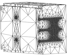 | Figure 6. Example of a fully discretised model, in this case series D |
Surface to surface contact elements were used. Sliding was permitted between the contacting steel plate and LVL surfaces, but without separation. Resistance to sliding was defined using a friction coefficient of 0.6, chosen as a high value to represent untreated surfaces.
4.3. Materials Properties of the Composite Components
The elastic properties of the individual materials involved in the analysis are summarised in Table 5. The nails and the steel plate are assumed to be isotropic, i.e.The x-axis is parallel to the grain. Materials properties for the LVL are input assuming orthotropy however, the elastic modulus and Poisson’s ratios pertaining to the two axes normal to the grain direction are equalised, i.e.The densities for the steel and LVL are 7900kgm-3 and 520kgm-3 respectively.| Table 5. Materials properties used in the models for steel and LVL |
| | Steel | LVL | | Ex/ GPa | 210 | 12.75 | | Ey/ GPa | 210 | 0.255 | | Ez/ GPa | 210 | 0.255 | | υxy | 0.27 | 0.03 | | υyz | 0.27 | 0.29 | | υxz | 0.27 | 0.03 | | Gxy/ GPa | 83 | 0.620 | | Gyz/ GPa | 83 | 0.620 | | Gxz/ GPa | 83 | 0.620 |
|
|
4.4. Application of Load and Boundary Conditions
A schematic of a beam segment is provided in Figure 7. The left hand side about the line of symmetry is not modelled but is included for clarity. Each beam segment for series A-E was subjected to nodal displacements parallel to the grain axis on the LVL. Displacements were applied through the depth of the LVL segment to achieve a maximum strain, in both compression and tension of 0.1%. Nodal degrees of freedom were bound on a plane representative of the beam’s axis of symmetry.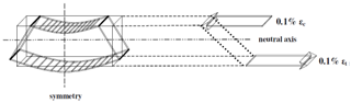 | Figure 7. Schematic illustration of the loading conditions causative to the bending characteristics of the beam segment. Nodal displacements are applied through the depth of the LVL until a maximum compressive strain, εc, and tensile strain, εt, of 0.1% is achieved |
5. Analysis of Beam Pairs Under Flexion
5.1. Failure Observations
All beams (in series A-E) experienced microbuckling on the compressive face of the LVL, which lead to larger scale buckling. As a consequence, the steel plates also buckled on the compressive face, most notably in the lower density nailing series. The long slender geometry of the steel plate made it susceptible to buckling under an applied load. Figure 8 (a) shows an example of gross compression buckling of the steel plates in a series A beam pair. Smaller compression buckles in the steel plates were experienced for the higher density nailing series and are a function of closing in the points of connection between the composite members. Catastrophic tensile fracture between the central rollers followed the onset of compression buckling in the LVL. In the lower density nailing series (A-C), where the spacing distances are relatively wide, tensile fracture did not visibly propagate from nail to nail. In the higher density nailing series (D and E) however, tensile fracture propagated from nail to nail along a path parallel to the grain axis, Figure 8 (b).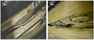 | Figure 8. (a) Gross compression buckling of the LVL and the steel plate reinforcement in a series A beam pair and (b) fracture path propagated horizontally in tension along from nail to nail in the higher series nailing densities, in this case, a series E beam |
The simulation results further showed that although nails lying along the neutral axis experienced little or no normal stress, all nails did experience shear loading. An immediate reaction might be to dismiss the usefulness of the nails placed along the beams axis of neutrality. However, resistance to vertical shear that develops between the LVL and the steel plate in the XY plane upon loading is increased through the presence of the centrally located nails. As a consequence of resisting vertical shear, there is a reduction in the vertical load-slip characteristics of the plate from the LVL beams and fuller composite action is made possible.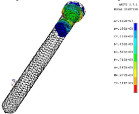 | Figure 9. Distribution of normal stresses within nails concentrated to the region where the nail is in contact with the steel plate. Units are in Pa |
Figure 10 shows the nails for each series from samples tested to destruction, the LVL having been cut away. There are generally no obvious signs of distortion in the nails, however some nails on the compression side of the beams have fractured. This could well be a consequence of compressive buckling although there is no certainty to this claim. The fact that the nails have not deformed to any great magnitude at the highest load carrying capacities confirms the applicability of the fasteners in flitch beams. A low degree of deformation in the fasteners implies a low degree of steel plate slippage from the LVL and therefore, fuller composite action is possible.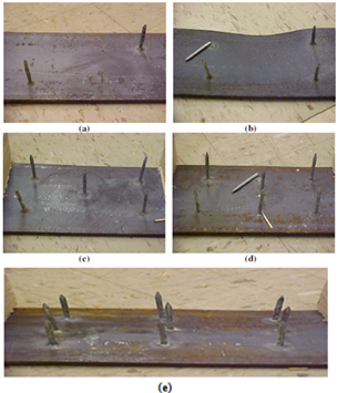 | Figure 10. (a)-(e) Nails in series A-E do not show any obvious signs of angular distortion. Fractured nails are observed only on the compression side of the beam |
5.2. Flexural Properties
Table 6 provides the values for the flexural strength, σf,max, and the flexural modulus, Ef, for every tested beam pair in each series. The flexural modulus is calculated using the Hookean principle for the composite stress and strain values in flexure. The flexural strength values are calculated according to Equation 3, which is an equation that has been modified from the advised equation in[11] to account for the section properties of the composite beam pair arrangement. An elastic section modulus is used as an approximation in Equation 3 and the flexural strength is an averaged global stress for the composite beam components.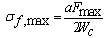 | (3) |
The median values of Ef and σf,max are emboldened in Table 6. Acknowledging the median values for a very small sample set eliminates potentially unrepresentative values if it is assumed that the data follows a normal distribution and the median value is central to the distribution. | Table 6. Values for the flexural modulus and flexural strength for all tested beams. Median values in each series are in bold |
| | Series | Beam Pair | Ef/ GPa | σf,max/ MPa | | A | 1 | 43.6 | 114.2 | | 2 | 37.1 | 110.8 | | 3 | 35.4 | 112.5 | | B | 1 | 38.6 | 107.7 | | 2 | 40.0 | 108.0 | | 3 | 38.2 | 108.0 | | C | 1 | 38.9 | 104.2 | | 2 | 31.4 | 104.7 | | 3 | 48.3 | 109.1 | | D | 1 | 33.4 | 100.5 | | 2 | 39.9 | 102.7 | | 3 | 46.9 | 90.4 | | E | 1 | 40.1 | 98.0 | | 2 | 43.3 | 98.7 | | 3 | 37.3 | 100.1 |
|
|
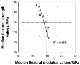 | Figure 11. Plot of the median values for the flexural strength against the flexural modulus. The range for each series is indicated for both axes by thin dashed bars. The thick linear dashed line is the best-fit line and an R2 regression fit of 0.9554 is achieved |
Figure 11 is a plot of the median values for σf,max against Ef. Error bars that are incorporated are indicative of the highest and lowest values within each series. A linear best-fit is assumed and applied to the points and an R2 value of 0.9554 is yielded for the regression fit of the points to the best-fit line. Given that the R2 value is high, it is plausible to claim that σf,max decreases as a function of increasing Ef, each of which lessens and heightens respectively as a function of increasing nailing density. It is however true that Ef does not rise significantly as the nailing density is increased, which suggests that the composite elements for beams A-E are already joined intimately for series A beams. The σf,max however, does show a decrease as the nailing density increases because the propagation of cracks from nail to nail becomes easier when the nail holes, acting as introduced defects, are located closer to each other.Steel-timber flitch beams manufactured by Coleman and Hurst[5] were also tested with varying nailing densities inserted into predrilled holes and subjected to an applied moment. The trend of increasing Ef with decreasing σf,max was not reported and indeed, the nailing density did not seem to affect the Ef or the σf,max significantly. Coleman and Hurst believed that there was a lack of variability in the nailing densities tested and that lower densities should be tested to enlarge the total range. The variability of nailing densities in the present study is believed to have been sufficient to show a trend between Ef and σf,max that arises as a result of increasing the nailing density.Within the elastic range and at equal strain, higher values for the flexural modulus will result in higher stresses if a linearly proportional relationship is assumed. Figure 12 shows a tri-axial plot where on one y-axis, the median Ef value is plotted against the nailing density and on the other y-axis, the FE-calculated normal stresses is plotted as a function of the nailing density. The stresses calculated by the model are the maximum stresses that occur in the nails when the composite beam segments for each series experience the same levels of axial strain. These stresses are calculated according to von Mises principles. Linear best-fit lines are applied to the Ef vs. nailing density points as well as for the stress vs. nailing density points. An R2 value of 0.9182 is evident for the Ef vs. nailing density. The R2 value for the model stresses vs. nailing density is 0.9323. In conclusion it is clear that the nail head stresses become progressively higher, for the same level of strain, as the beam stiffness increases. This is of course the expected outcome.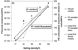 | Figure 12. Tri-axial graph showing Ef and FE calculated stresses on y-axes each as a function of the nailing density |
6. Conclusions
Steel-LVL flitch beams were manufactured with five different nailing densities and subjected to flexure. When the nailing density on the compressive faces of the beams was smaller, the compressive buckles in the steel were more considerable. Tensile fracture in the higher density nailing series propagated from nail hole to nail hole, whereas in the lower density nailing series the tensile fracture paths propagated seemingly arbitrarily. For all beam series, FE models showed that high localised normal stresses develop in the nails at the steel-LVL interface closest to the outermost fibres of the beams. The nails located along the neutral axis experience significantly lower stresses. Shear stresses that develop in the nails at the plate-timber interface are however, relatively evenly distributed throughout the depth of the beam. The nails located at the neutral axis therefore increase resistance to interfacial slip between the composite elements even though their resistance to axial normal stress is effectively zero. The flexural modulus cannot clearly be said to increase as a function of increasing nailing density. This verifies that the contribution of steel to the stiffness of the composite is achieved with the lowest nailing density. The flexural strength decreases as a function of increasing nailing density. This is because the introduction of more nail hole defects makes crack propagation easier when deformation is non-recoverable.
References
| [1] | ASCE (1972); Wood structures, a design guide and commentary; section 8.6.3.2 |
| [2] | Ban, S., Tsubota, H., Motohashi, S. and Yoshida, A. (1999); Nagano Olympic memorial arena; proceedings of the Pacific Timber Engineering Conference; Rotorua, New Zealand, Vol. 1 pp. 139-230 |
| [3] | Sliker, A. (1962); Reinforced wood laminated beams; Forest Products Journal, Vol. 12 No. 12 pp. 91-96 |
| [4] | Stern, E. G. and Kumar, V. K. (1973); Flitch beams; Forest Products Journal, Vol. 23 No. 5 pp. 40-47 |
| [5] | Coleman, G. E. and Hurst, H. T. (1974); Timber structures reinforced with light gage steel; Forest Products Journal, Vol. 24 no. 7 pp. 45-53 |
| [6] | Borgin, K. B., Loedolff, G. F. and Saunders, G. R. (1968); Laminated wood beams reinforced with steel strips; ASCE Journal of the Structural Division, Vol. 94 No. ST7 pp. 1681-1705 |
| [7] | Brunner, M. (2002); Theoretical strength limits of timber beams fortified with prestressed artificial fibres; Proceedings of the 7th World Conference on Timber Engineering; Shah Alam, Malaysia |
| [8] | DD ENV1995-1-1 (1994); Eurocode 5: Design of timber structures – Part 1.1: General rules and rules for buildings; British Standards Institution, |
| [9] | Hoyle, R. J. (1975); Steel-reinforced wood beam design; Forest Products Journal, Vol. 25 No. 4 pp. 17-23 |
| [10] | Jones, R. (1997); Upgrading of timber members in historic buildings; Journal of the ; Vol. 14 No. 4 pp. 192-203 |
| [11] | BS EN 408 (1995); Timber structures. Structural timber and glued laminated timber. Determination of some physical and mechanical properties; British Standards Institution, |
 Abstract
 Reference
 Full-Text PDF
 Full-Text HTML