Mayank Suhirid 1, Kiran B Ladhane 1, Mahendra Singh 1, Vishwas A Sawant 2
1Department of Civil Engineering, Indian Institute of Technology Roorkee, Roorkee, 247667, India
2School of Engineering, Edith Cowan University, Perth, 6027, Australia
Correspondence to: Vishwas A Sawant , School of Engineering, Edith Cowan University, Perth, 6027, Australia.
| Email: |  |
Copyright © 2012 Scientific & Academic Publishing. All Rights Reserved.
Abstract
In the present work it has been proposed to study the pier foundation of bridge supported on two piers. The piers are situated on left and right bank of river. The rocks present at site indicate presence of lower Shiwalik rocks with alteration of sandstone/ clay rocks. A finite difference scheme is used to analysis the pier rock socket foundation. A computer code is developed in FORTRAN 90 to determine the displacements and stresses at each node of discrtized rock domain. By using this methodology lateral load capacity of rock socketed pier foundation is to be determine.
Keywords:
Finite Difference Method, Rockmass Deformation Modulus, Lateral Load Capacity, Rock Socketed Pier
Cite this paper:
Mayank Suhirid , Kiran B Ladhane , Mahendra Singh , Vishwas A Sawant , "Lateral Load Capacity of Rock Socketed Piers Using Finite Difference Approach", Journal of Civil Engineering Research, Vol. 1 No. 1, 2011, pp. 1-8. doi: 10.5923/j.jce.20110101.01.
1. Introduction
Often the foundations of heavy structures like multi-storeyed buildings, bridges and dams are placed on rock mass. Rock masses in nature contain numerous discontinuities as cracks, joints, cleavages, beddings and/ or even faults. Deformation and failure of rock mass are greatly dependent on the presence of such geological discontinuities. For this reason, greater degree of conservation is exercised in the estimation of load carrying capacity and resulting deformation of rock mass. Foundations are designed to be safe against these essential requirements. The compressive loads from the structures whether vertical, inclined or horizontal will have to be transmitted to the rock mass through individual spread footing, strip, mat, caisson or pile shaft and its tip. Rock sockets are provided as foundation of bridge piers and estimation of lateral load capacity of rock sockets is a challenging task till date. There are a numerous factors which impart special influence on the construction and design of any bridge pier foundation. Structural parameters, Geotechnical and Geological parameters, loading conditions, fund and economy are few of them as most noteworthy.Maheshwari and Madhav (2006) proposed a numerical procedure for the elastic analysis of the vertical deformation and the stress distribution of the strip footings on layered soil media. The soil media is discrtized and using the theory of elasticity, the governing differential equations are obtained in terms of vertical and horizontal displacements. These equations along with appropriate boundary and continuityconditions are solved by using the finite difference method. The vertical and horizontal displacements, strains and stresses are found at various nodes in the soil media. Rajasekar and Madhav (2010) proposed a elastic continuum and Vlasov model for estimation of distribution of displacement and stresses in the soil mass resulting from the load applied at or below the surface of soil foundation interaction. A procedure is proposed to estimate the parameters E & G by direct shear test. A simple two parameter model based on uncoupled deformation, E and shear G, moduli is proposed for estimating stresses and displacement under a rigid or uniformly loaded circular footing on finite layer. Various research workers have used techniques like finite element method, boundary element method, integral transforms technique and other numerical procedures for the analysis of footings on rockmass. In this paper, an attempt has been made to present a simplistic solution for the analysis of footing founded on a rockmass using theory of elasticity approach. In this approach, well known finite difference method has been used to solve equations of equilibrium and compatibility with due consideration to appropriate boundary and continuity conditions of the problem.
2. Statement of the Problem
A large number of infrastructural development activities are being undertaken in the Himalayan region. A valley site is considered in the present study for constructing a bridge. It is considered that a box girder bridge will be constructed which will be supported on two piers. These piers will be formed on side slopes in the valley. As an initial design rock sockets of 8m chamber and 6m chamber are provided below the two piers. Bore hole data available from the vicinity of the site is used for estimating rock mass properties. Finite difference approach is used to analyze continuum medium for obtaining stress-strain behaviour of the foundation subjected to vertical and horizontal load. Lateral load capacity is then decided based on permissible deflection at the base of the foundation.
3. Rock Mass Modulus
Modulus of deformation of rock mass is very important parameter while analyzing the continuum medium with stress equilibrium equations. It is obtained from different approaches by using different empirical relations. They are based on different approaches (RMR, RQD, GSI etc.) Hoek and Diederichs (2006) have suggested the following expressions for the rock mass modulus based on GSI: | (1) |
 | (2) |
Where Ei is the intact rock modulus and D is the damage factor. Barton (2002) has suggested the following expression for rock mass modulus in terms of rock mass quality, Q: | (3) |
In which, σci is the intact rock strength in MPa. Expressions have also been suggested by various investigators based on RMR as given below:Serafim and Periara (1983) | (4) |
Mehrotra (1992): | (5) |
Ramamurthy (2007) | (6) |
Zhang (2009) | (7) |
Using these empirical relationships, the average value of modulus of deformation of rock were obtained as 0.91 GPa on the left bank and 1.73 GPa on the right bank.
4. Analysis and Formulation
To obtain the displacement and stress pattern, the rock media has been modelled with specified boundary condition at each node as shown in Figure 1. The rock media consists of single rock layers. The layer is founded on a rigid base and the rock modulus and Poisson ratio of the layers have been denoted as (E, ν) respectively. The footing is acted upon by lateral load intensity, q, over a diameter of socketed pier at the ground level, i.e. at the top of rock layer. The Poisson ratio for concrete is considered to be 0.2 and from the field data the Poisson ratio for rock on left bank and right bank is considered to be 0.3 and 0.2488 respectively. In the Figure 1 ΔZ is the vertical spacing of each node, while Δx1 and Δx2 are the horizontal spacing of each node. The rock media is analysed in a two-dimensional plane using finite difference method to get displacements u and w in x and z directions, respectively. 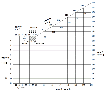 | Figure 1. Discretization of the rock domain |
The stress-strain relationship for 3D continuum is given as follows: | (8) |
For plane-strain condition (εy =0, νxy=νzy =0, τxy =τzy =0) | (9) |
 | (10) |
Using the well known relationships for Lames constant λ and shear modulus G asThe equation (10) can be rewritten as  | (11) |
By expressing strains in terms of displacements 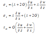 | (12) |
The stress equilibrium relations at any point are defined as follows:  | (13) |
 | (14) |
Substitution of stress-displacement relations in the stress equilibrium relations yield following set of equations: | (15) |
 | (16) |
Applying central finite difference scheme to express the derivatives, the above equations are transformed to following relationships in terms of displacements u and w. | (17) |
 | (18) |
The above equations can be applied in interior domain without any modification. But implementation of the above equations to the boundary nodes requires some modification, since it involves fictitious nodes which have to be removed with proper boundary conditions. The nodes numbers are depicted in Figure 1. They have different boundary conditions. The bottom and left hand side boundary are fixed then the displacement in x and z direction ( u=0 and w=0). The node 56 lies between the boundary of rockmass and concrete socket. If the Lames constant and shear modulus is defined as λL and GL at the left side, λR and GR at the right side , λU and GU at the upper side and λb and Gb at the base of node 56, then equations for u and w for different specific nodes using appropriate difference scheme are obtained and outlined in the Appendix. Then these system of equations are solved for unknown nodal displacements by matrix inverse. Flow chart and algorithm of the computational procedure is outlined in the Figure 2.
4.1. Material and Geometrical Properties
The pier banks consist of a column with circular shaft resting in a socketed rock.Dimensions of rock mass domain = 21.5m × 21.5m × 18m Pier shaft diameter 4.25m Pier shaft depth 6m for left bank pier Pier shaft depth 8m for right bank pier Pier dimensions cross-section 2.7m × 5.5m, height- 6mFor the analysis of pier on left bank and right bank the vertical load (Fz), lateral load (Fx) and transverse moment (M) acting on pier is transferred to the footing in the form of horizontal and vertical stresses. Material properties and forces are summarized in Table 1. For the analysis of pier on left bank and right bank two case are considered:Case 1: Vertical load acting on pier is considered. Case 2: Vertical load acting on pier is not considered.While plotting the graphs on different horizontal planes, total five planes were considered (D1 to D5) starting from 0 to 60 m depth an interval of 12 m. Similarly while plotting the graphs on vertical planes three different planes at different horizontal distances are considered (DW2, DW3, and DW4).| Table 1. Material Properties and Design Load |
| | Material Properties | Right bank | Left bank | | Rock modulus (GPa) | 0.91 | 1.73 GPa | | Poisson ratio | 0.248 | 0.3 | | Young modulus of concrete (GPa) | 27.38 | 27.38 GPa | | Poisson ratio of concrete | 0.2 | 0.2 | | External Forces | Fx =1350 kN, Fz =64079 kN,M=13769 kN-m |
|
|
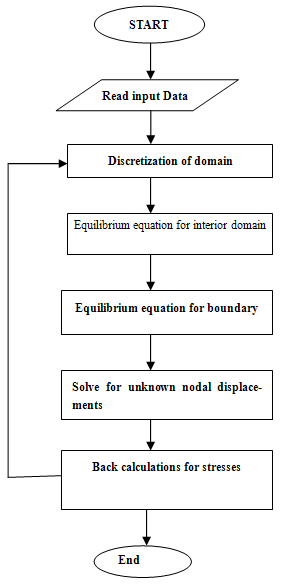 | Figure 2. Flow Chart of Computational Procedure |
5. Results and Discussions
From linear interpolation the lateral load capacity of bridge piers are found to be as follows:Right bank pier with vertical load= 92.78 kNRight bank pier without vertical load= 267.25 kNLeft bank pier with vertical load = 171.8 kNLeft bank pier without vertical load = 503.1 kN| Table 2. Summary of stress-strain analysis |
| | Pier | Node | Horizontal displacement(u)at footing (cm) | Predicted displacement at top of pier(cm) | Lateral load capacity (kN) | | Case 1 | Vertical load is considered | | Right bank | 56 | 20.05 | 145.5 | 92.78 | | 57 | 17.68 | | Left bank | 56 | 5.27 | 78.57 | 171.80 | | 57 | 17.67 | | Case 2 | Vertical load is not considered | | Right bank | 56 | 20.05 | 50.5 | 267.246 | | 57 | 17.68 | | Left bank | 56 | 5.27 | 26.72 | 503.10 | | 57 | 17.67 |
|
|
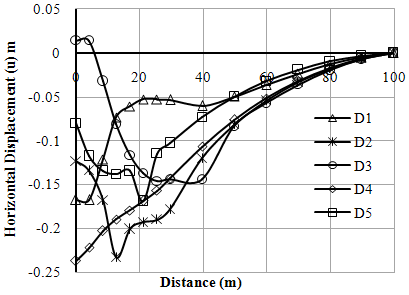 | Figure 3. Variation of horizontal displacements (u) with distance (Left Bank-Case-I) |
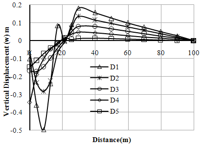 | Figure 4. Variation of vertical displacements (w) with distance (Left Bank-Case-I) |
It is observed that lateral load carrying capacity for both left and right pier is considerable low for the loading condition when vertical loads from the superstructure is considered as compared to loading condition when no loading condition. The geometry of slope and rockmass mechanical characteristics are such that tilting occurs when vertical load acts. As without lateral load is hypothetic the allowable lateral load capacity is worked out to be 92.78 kN and 171.8 kN for left and right bank respectively. These values are very low and warrant redesign of the socket with much greater abutment to reduce differential settlement and enhance lateral load capacity.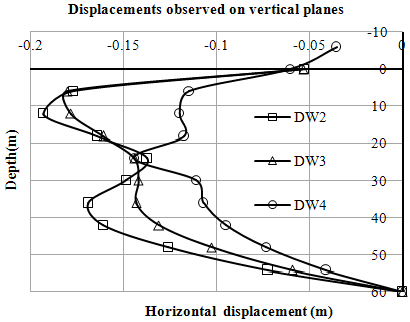 | Figure 5. Variation of horizontal displacements (u) with depth (Left Bank-Case-I) |
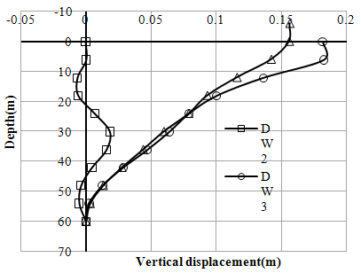 | Figure 6. Variation of vertical displacements (w) with depth (Left Bank-Case-I) |
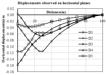 | Figure 7. Variation of horizontal displacements (u) with distance (Left Bank-Case-II) |
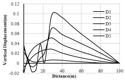 | Figure 8. Variation of vertical displacements (w) with distance (Left Bank-Case-II) |
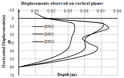 | Figure 9. Variation of horizontal displacements (u) with depth (Left Bank-Case-II) |
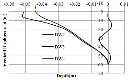 | Figure 10. Variation of vertical displacements (w) with depth (Left Bank-Case-II) |
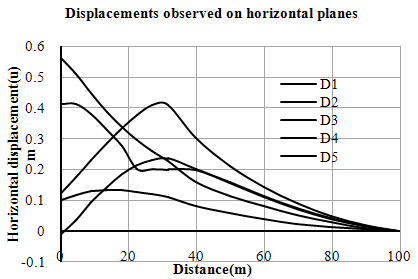 | Figure 11. Variation of horizontal displacements (u) with distance (Right Bank-Case-I) |
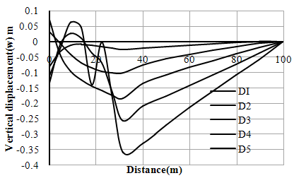 | Figure 12. Variation of horizontal displacements (w) with distance (Right Bank-Case-I) |
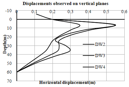 | Figure 13. Variation of horizontal displacements (u) with depth (Right Bank-Case-I) |
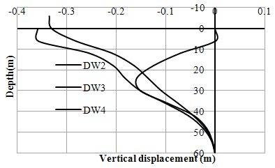 | Figure 14. Variation of vertical displacements (w) with depth (Right Bank-Case-I) |
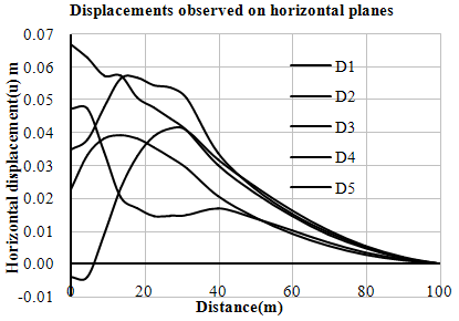 | Figure 15. Variation of horizontal displacements (u) with distance (Right Bank-Case- II) |
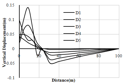 | Figure 16. Variation of vertical Displacements (w) with distance (Right Bank-Case- II) |
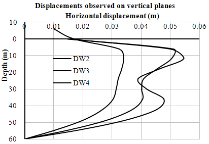 | Figure 17. Variation of horizontal displacements (u) with depth (Right Bank-Case- II) |
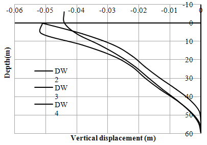 | Figure 18. Variation of vertical displacements (w) with depth (Right Bank-Case- II) |
6. Conclusions
In present study rock socket provided for pier foundation at left and right bank of a river has been analysis for stress-strain behaviour. The rock socket has been provided for slopping ground. Continuum mechanics approach have been used and finite difference scheme has been employed to analysis the problem, while implementing finite difference scheme mapping technique was use for slopping domain. Following concluding remarks are offered from the outcome of present study.1. Using the classification approach and rock mass characteristics encountered at the site the rock mass modulus is estimated to be 0.91GPa and 1.733 GPa on right and right bank pier subsoil strata respectively. 2. Maximum displacement occurs at the free end of the rock slope domain. Also maximum horizontal and vertical stresses are developed below the footing of rock domain for both cases. The parameters displacements are observed to be decreasing with the distance from the edge of the footing in the slope zone.3. Two distinct trends are observed in the variation of vertical and horizontal displacements graphs plotted on horizontal planes. From surface to footing, the trend shows maximum values with considerable variation. From edge of footing to inner side of slope, the displacement curves are relatively flatter with less variation with values decreasing with the distance. 4. It is observed that the vertical load coming from the super structure is quiet significant and it is also affecting the lateral load capacity of pier. Lateral load capacity of pier is higher in the absence of vertical load. 5. Length of socket also has considerable impact on the response observed for 6m pier on left bank and 8m for right bank are totally different .As observed from there tilt.
Appendix
Node 56 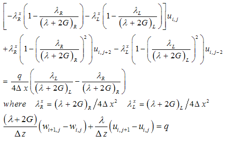 Node 57
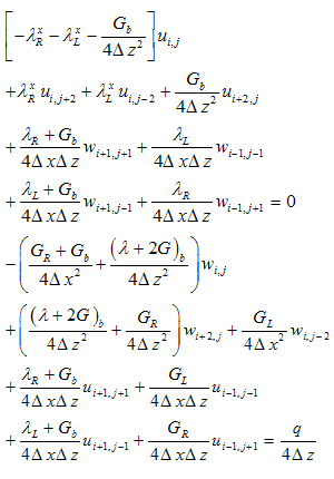 Node 67
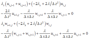 Node 68
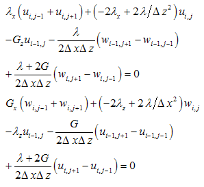 Node 78
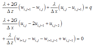 Node79
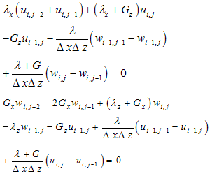 Node 89,101, 114,128,143 and 159
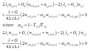 Node 102,115,129,144 and 160
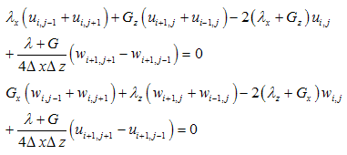
References
| [1] | Barton, N., 1980, Application of the Q-system in design decisions, In: Bergman M, editor. Subsurface space, vol. 2, 553–61 |
| [2] | Barton, N., 2002, Some new Q-value correlations to assist in site characterization and tunnel design, Int. J Rock Mech. Min. Sci., 39(2),185–216 |
| [3] | Bieniawski, Z. T., 1978, Determining rock mass deformability: experience from case histories, Int. J Rock Mech. Min. Sci. Geomech., 15, 237–48 |
| [4] | Coon, R. F. and Merritt, A. H., 1970, Predicting in situ modulus of deformation using rock quality indices, In: Determination of the In Situ Modulus of Deformation of Rock, ASTM STP 477, Philadelphia, 154–73 |
| [5] | Hoek, E. and Diederichs, M. S., 2006, Empirical estimation of rock mass modulus, Int. J. Rock Mech. Min. Sci., 36, 203–215 |
| [6] | Hoek, E., 2000, A geologically friendly tool for rock mass strength estimation, Proc. GeoEng2000 Conference, Melbourne, 1422-1442 |
| [7] | Kulhawy, F. H., 1978, Geomechanical model for rock foundation settlement, Journal of Geotech. Engg., ASCE, 104, 211–27 |
| [8] | Maheshwari, P. and Madhav, M. R., 2006, Analysis of Rigid Footing lying on Three –Layered Soil using the Finite Difference Method, Geotechnical and Geological Engineering, 24, 851-869 |
| [9] | Maheshwari, P. and Viladkar, M. N., 2007, Strip Footings on a Three Layer Soil System: Theory of Elastic Approach, International Journal of Geotechnical Engineering, 1, 47-59 |
| [10] | Mehrotra, V. K., 1992, Estimation of Engineering Parameters of Rock Mass, PhD thesis, University of Roorkee, Roorkee, India |
| [11] | Poulos, H. G., 1971, Laterally Loaded Piles: Ill-Socketed Piles, Journal of Soil Mechanics and Foundation Division, ASCE, 341-360 |
| [12] | Ramamurthy, T., 1993, Strength and modulus response of anisotropic rocks, In: Hudson JA (ed) Compressive rock engineering- principle, practice and projects, vol. 1, Pergamon Press, Oxford,. 313–329 |
| [13] | Rajasekar M. and Madhav M, R., 2010, New Two Parameter Model With Uncoupled Moduli for Ground, Indian Geotechnical conference -2010, 49-56 |
| [14] | Serafim, J. L., 1983, Consideration of the geomechanical classification of Bieniawski, In: Proceedings of international symposium on engineering geology and underground Construction, Lisbon, Portugal, vol. 1(II), 33–44 |
| [15] | Wang ,S. and Kulatilake, 1993, PHSW Linking between joint geometry models and a distinct element method in three dimensions to perform stress analyses in rock masses containing finite size joints, Soils and Foundation, 33, 88–98 |
| [16] | Zhang, L., 2009, Estimating Strength of Jointed Rock Masses, Rock Mech. Rock Engg., 23, 91-112 |


 Node 57
 Node 67
 Node 68
 Node 78
 Node79
 Node 89,101, 114,128,143 and 159
 Node 102,115,129,144 and 160
 Abstract
 Reference
 Full-Text PDF
 Full-Text HTML