Yannick Devario Youssi Bang1, 2, Moussa Sali3, Pierre Marcel Noah1, 2, Fabien Kenmogne4, Danao Adile Adoum5, Atangana Ateba1, 2
1Laboratory of Mechanics University of Douala, Cameroon
2Department of Mechanical Engineering, ENSET, University of Douala, Cameroon
3Laboratory of Energy, Materials Modelling and Methods (E3M), Douala, Cameroon
4Department of Civil Engineering, Higher Teacher Training College of the Technical Education (ENSET), University of Douala, Cameroon
5Department of Industrial Engineering and Maintenance, Polytechnic University of Mongo, Chad
Correspondence to: Fabien Kenmogne, Department of Civil Engineering, Higher Teacher Training College of the Technical Education (ENSET), University of Douala, Cameroon.
| Email: |  |
Copyright © 2021 The Author(s). Published by Scientific & Academic Publishing.
This work is licensed under the Creative Commons Attribution International License (CC BY).
http://creativecommons.org/licenses/by/4.0/

Abstract
The purpose of this paper is to show the impact of the stiffness formulation on a prismatic shell of rectangular cross-section, subjected to a flexural stress. Firstly, the stiffness is formulated by adopting both the linear and quadratic formulations, which are introduced into the Lagrange equation for a plate with variable stiffness to derive the ordinary differential equation of the system. Next according to the complexity of the obtained equation, the numerical investigations are performed by using the Gauss-Seidel algorithm, with application on a box bridge with two embedded edges, and by considering both the linear and quadratic stiffness. The results obtained show that there are significant differences between displacements of both linear and quadratic stiffness, with that of the quadratic stiffness very close to real physical observations.
Keywords:
Prismatic shell, Plate, Variable stiffness
Cite this paper: Yannick Devario Youssi Bang, Moussa Sali, Pierre Marcel Noah, Fabien Kenmogne, Danao Adile Adoum, Atangana Ateba, Prismatic Bending Shell with Variable Rigidity, International Journal of Advanced and Multidisciplinary Engineering Science, Vol. 4 No. 1, 2021, pp. 1-6. doi: 10.5923/j.james.20210401.01.
1. Introduction
Prismatic plates and shells were widely used in mechanical engineering and heavy boiler making. Sails, rafts and floors in civil engineering works are usually plates or hulls as well. This type of structure was found in aircraft and shipbuilding (see [1] and references therein), for example the aircraft cabin or the hull of a ship. In addition to mechanical engineering, washers, cylinder head, pistons, cylinders, gearboxes are also plates or shells. In the field of shipbuilding, it was a common practice to idealize ship structures as thin-walled beams with a rigid cross-section for their analysis. The cross-section of the ship hull is, however, normally a combination of open and closed parts with variable cross sections. Thin-walled beams are structural members acted upon by axial, bending and twisting loads. A thin-walled beam is characterized by the fact that their three dimensions are all of different order of magnitude. The thickness of the wall is small compared to any other characteristic dimension of the cross section, and the cross sectional dimensions are small compared to the length of the beam.The calculation of such structures must be accurate and easy to perform, since these structures are often subjected to static and/or dynamic loads. Despite the practical importance of elements of this type identified in a number of works, many questions related to their calculation are still relevant today. Numerous researchers’ works address the problem of plates and shells (see for eg. [2-9]) much more for plates and shells of constant rather than variable stiffness [7,9] have worked on plates with variable stiffness and [5] more interested in thickness variability by varying the thickness along a straight line and according to a quadratic formulation. It is in this lance that our paper is fixed. By focusing on a linear stiffness formulation on one hand, and a quadratic formulation on the other hand. The method we used in this study consisted in writing the basic formulation equations of the bent prismatic shell stiffness, with variable stiffness allowing us to solve numerically the established equation. Next we give results for loads distributed over the surface of our shell without axial loads using finite difference methods. The calculation of these structures required the implementation of increasingly sophisticated mechanical behaviour modeling tools, taking into account the specificities of these structures. After a summary and introduction of our work, we continue by establishing the LAGRANGE equation for a flex hull. Subsequently the boundary conditions are established and a numerical resolution is applied to the case of a box deck. The last part is reserved for results and discussion.
2. Differential Equation for Prismatic Hulls with Variable Stiffness
2.1. The Differential Equation of the Deflection Surface of a Variable Stiffness Plate
Let us consider the plate shown in Figure 1 below, whose average plane is represented by  . Let
. Let  and
and  be the dimensions of a surface element taken from this plate.
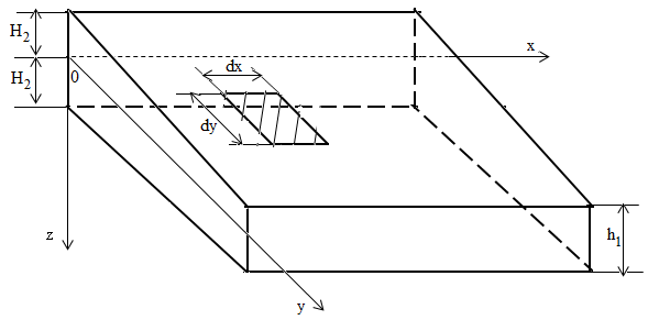 | Figure 1. Representation of a surface element on the plate |
We assume that the load acting on a plate is normal to its surface and that the deflections are small as compare to the thickness of the plate. At the boundary, we assume that the edges of the plate are free to move in the plane of the platen, thus the reactive forces at the edges are normal to the plate. With these assumptions we can neglect any deformation in the median plane of the plate during loading. Let us consider the x and y coordinate axes in the median plane of the plate and the z-axis perpendicular to this plane, with an element cut out of the plate by two pairs of planes parallel to the  and
and  planes, as shown in Figure 2.
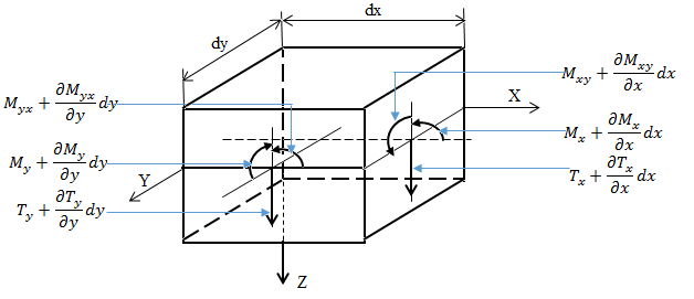 | Figure 2. Modeling of a surface element |
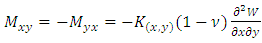
In addition to the bending moments Mx and My and the torsional moments Mxy, there are vertical1 shear forces acting on the sides of the element. These shear forces per unit length parallel to the y and x axes, which we refer as Tx and Ty respectively, are equivalent to [4,9]: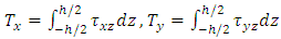 | (1) |
Since the moments and shear forces are functions of the x and y coordinates, in discussing the equilibrium conditions of the element we must take into account the small changes in these quantities when the x and y coordinates change by the small quantities dx and dy. The median plane of the element is shown in Figures 3 a and b, and the directions in which the moments and forces are considered positive are indicated. The load distributed on the upper side of the plate must also be considered. The magnitude of this load is noted as q, so that the load acting on element 1 is qdxdy. | Figure 3. Representation of an average surface of a plate, (a): with moments, (b) with sharp shearing strains |
If we project the forces in the z-axis direction, we obtain the following equation: 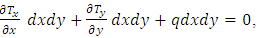 leading after simplification to the following partial differential equation:
 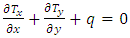 | (2) |
By projecting the moments following the x-axis we obtain 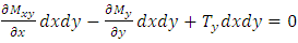 , leading after simplification to
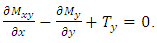 | (3) |
For the y direction, one has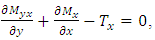 | (4) |
which can be substituted into Eq. (1) to give 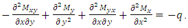 By setting
  the above equation can be simplified to give:
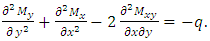 | (5) |
Considering the following equations [7,8]: 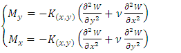 | (6) |
 | (7) |
and accounting Eqs. (5) and (6) into Eq. (4) one has: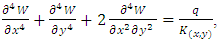 | (8) |
which is Green Lagrange's characteristic equation for a constant stiffness bent plate, which by introducing the Hamiltonian operator 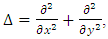 can also be put in the following form:
 | (9) |
Equations (3) and (4) then become;  | (10) |
 | (11) |
Substituting equations (5) and (6) into (4), considering that the flexural stiffness K(x, y) is variable, as a function of the cartesian coordinates x and y we obtain the following equation governing the bending of a plate where the stiffness (thickness) varies according to any law [4].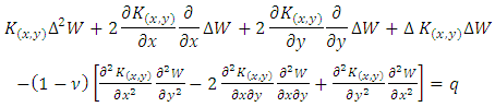 | (12) |
where, W is the displacement of a point on the average surface.After mathematical transformations, we obtain the fourth-order equation (12) in this form: | (13) |
Let's set: 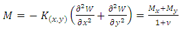 | (14) |
leading to the following system of second order partial differential equations: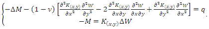 | (15) |
In order to solve this system of equations, one needs the definition of the stiffness form. For this purpose, we will consider that the flexural stiffness can be written according to two cases and assess the results by going through its formulation beforehand. - Firstly, the case where the plate is continuous and homogeneous with a constant stiffness K(x, y) as follows [3,4,8],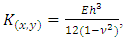 | (16) |
leading the first line Eq. (15) to  - Secondly, let’s consider the case of prismatic shells with second order polynomial variable rigidity as
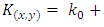
 where;
  are constant coefficients, meaning that Eq. (15) will be read:
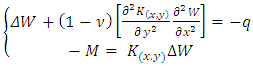 | (17) |
2.2. Boundary Conditions
We begin the discussion of boundary conditions with the case of a shell with a rectangular cross-section and assume that x and y axes are taken parallel to the sides of the shell.
2.2.1. Recessed Edge
If the edge of a hull is recessed, the deflection and bending moment along that edge are zero and the tangent plane to the bent median surface along that edge coincides with the initial position of the median plane of the hull. Assuming that the recessed edge is given by x = a, the boundary conditions are: 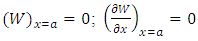 | (18) |
which is the mixed boundary conditions.
3. Application: Numerical Investigations
3.1. Preliminary
Let us consider the caisson bridge where the structure is homogeneous and isotropic as given below, which is embedded at its ends  and
and  and which supports a surface load
  .
.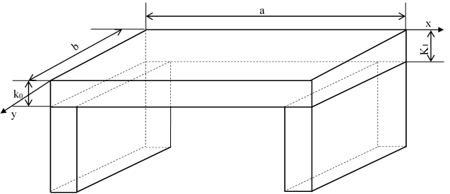 | Figure 4. Caisson brige |
In order to solve numerically the simplified form of the set of Eq. (15), as given by Eq. (17), the Gauss-Seidel algorithm [10] is used after rewriting this set of equations as: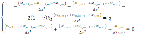 | (19) |
leading to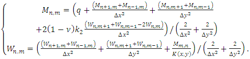 | (20) |
Following the Gauss-Seidel method, we seek  and
and  as a numerical sequence, by rewritten (20) as:
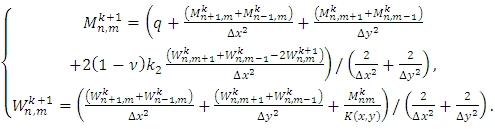 | (21) |
This equation is progressively iterated, starting from the initial conditions 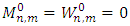 , with
  , and
, and  , and with boundary conditions given by Eq. (18), while the operation is repeated until
 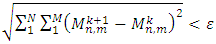 , and
, and 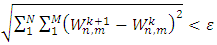 , with
  , or for a sufficient large value of
  In order to do this, we arbitrary choose
3.2. Results and Discussions
Let us first iterate the set of Eq. (21) by taking as parameters:  , E=300,
  ,
,  , b=10,
  , leading to
 and by choosing as spatial step
  In Figure 5, the results obtained for
  is shown, from where it appears that the displacement (Fig 5a) is more accentuated than the bending moment (Fig 5b). It is obvious here that the bending moment has a regular shape as for similar loads of plates with constant stiffness and the displacement approaches the origin, which is identical to result already found in [4,8] for the case of the hydrostatic loadings. Next in Figure 6 plotted for
 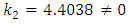 we notice a more refined bending moment, and a very serious stretching of the fibers in the case of displacement, which probably could justify some experimental results.
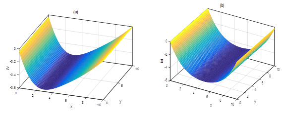 | Figure 5. (a): Displacement  (b): Moment (b): Moment  obtained for: obtained for:  leading to leading to  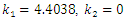 |
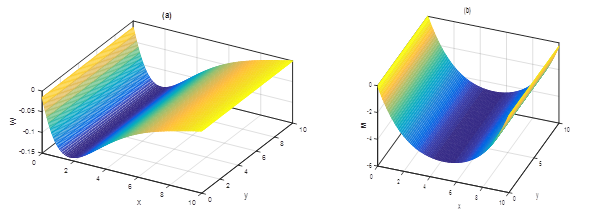 | Figure 6. (a): Displacement  (b): (b):  obtained for: obtained for:  leading to leading to   |
4. Conclusions
In this paper, we have studied the behavior of prismatic bending shell with variable rigidity submitted to constant flexural stress. These studies can find applications in mechanical engineering and heavy boiler making, as well as in sails, rafts, aircraft, shipbuilding and floors in civil engineering works. First of all, we have derived the equation governing the state of prismatic hulls with constant rigidity and submitted to constant uniformly load, which was numerically solved using the Gauss-Seidel algorithm, with application on a box bridge with two embedded edges. The results obtained showed that there were significant differences between displacements of both the case of linear and quadratic stiffness, with that of the quadratic stiffness very close to real physical observations.
Note
1. There will be no horizontal shear forces and normal forces on the wall of the element, since the pressure on the average surface of the plate is assumed to be neglected.
References
| [1] | Mahmood hossain, "A beam model for the structures of ship hull girder" master of engineering mechanical and manufacturing engineering, April 1997 (online). |
| [2] | M. BELGASMIA and M. GUENFOUD, "Etude aux valeurs propres des plaques et coques rectilignes par la méthode des bandes finies," Science et Technologie B, no. 31, Juin 2010. |
| [3] | L. D. Fischer, "Über die singulären Grundlösungen der Differentialgleichung für die Plattenbiegung mit veränderlicher Steifigkeit," Juni 1966. |
| [4] | H. FAVRE and B. GILG, "la plaque rectangulaire fléchie d'épaisseur lineairement variable," ZAMP, Zurich. |
| [5] | S. FAYOLLE, "SSLS133 - Plaque en flexion à épaisseur variable," Code_aster, 03/08/2011. |
| [6] | X. CASACC and G. R, "Etude de la flexion des coques toriques d'épaisseur constante chargées axisymétriquement: Application au calcul des soufflets toriques," LA HOUILLE BLANCHE, JANV. -FÉV. 1962. |
| [7] | M. SALI, F. LONTSI, O. HAMANDJODA and D. RAIDANDI, "calculation of plates on Elastic Foundation by the Géneralized Equations of Finite Difference Method," The International Journal of Engineering and Science (IJES), vol. 7, pp. 32-38, 2018. |
| [8] | M. SALI, A. NJIFENJOU and S. YOUSSOUFA, "Équations généralisées de la méthode des différences finies pour le calcul des plaques minces isotropes soumises à une flexion, compression, traction," Afrique SCIENCE 15(3) (2019) 49 - 63, pp. 49-63, 2019. |
| [9] | S. TIMOSHENKO and S. WOINOWSKY-KRIEGER, Theory of plates and shells, McGRAW-HILL BOOK COMPANY, 1989. |
| [10] | Z. -Q. Luo, P. Tseng. "On the convergence of the coordinate descent method for convex differentiable minimization". Journal of Optimization Theory and Applications, 72, 7–35 (1992). |

 Abstract
 Reference
 Full-Text PDF
 Full-text HTML