-
Paper Information
- Paper Submission
-
Journal Information
- About This Journal
- Editorial Board
- Current Issue
- Archive
- Author Guidelines
- Contact Us
International Journal of Advanced and Multidisciplinary Engineering Science
2017; 1(1): 1-10
doi:10.5923/j.james.20170101.01

Direct Contact Heat Exchange for Energy Recovery from Hot Temperature Petroleum Refinery Streams
 Abstract
 Reference
 Full-Text PDF
 Full-text HTML
Ibtisam Kamal1, Abdulsamad Abdulhammed2, Talib Ibrahim3, Shagul Muslih2, Bokan Umer2
1Soran University, Kurdistan Region, Iraq
2Department of Chemical Engineering, Faculty of Engineering, Soran University, Kurdistan Region, Iraq
3College of Engineering, Knowledge University, Kurdistan Region, Iraq
Correspondence to: Ibtisam Kamal, Soran University, Kurdistan Region, Iraq.
| Email: |  |
Copyright © 2017 Scientific & Academic Publishing. All Rights Reserved.
This work is licensed under the Creative Commons Attribution International License (CC BY).
http://creativecommons.org/licenses/by/4.0/

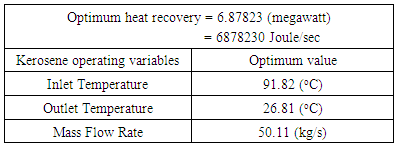
Industrial plants are huge consumers of energy, these plants are installing heat exchangers in an effort to reduce energy consumption, and so improve operating efficiencies. Limited numbers of experimental and numerical investigations have dealt with the parameters affecting the heat transfer aspects in single phase direct contact heat exchangers which may be selected for their high thermal efficiency and minimum capital investment. In oil refineries energy from hot temperature oil streams can be recovered by transfer directly to a cheap coolant liquid in liquid-liquid direct contact heat exchangers. The heat recovered from these heat exchangers has different applications including preheating boiler feed water and preheating wash water. Heat recovery from hot temperature refinery products using direct contact heat exchanger throughout a theoretical phenomenological study is central to the theme of this paper. Kerosene-water system has been chosen. The effect of the heating fluid inlet temperature (65-97.50)°C, and mass flow rate (25 to 45) kg/s on direct contact heat exchanger design parameters and heat transfer characteristics were investigated theoretically throughout nine cases. Correlations of heat recovered from the system as well as design and operating characteristics of the heat exchanger were estimated. Increasing kerosene flow rate found to associate directly with increasing the contact surface area, number of plates, number of channels per pass and pressure drop, while when the heat exchanger is designed to operates at high kerosene inlet temperature, big heat exchangers with large areas, high number of plates and channels per pass are needed for efficient heat exchanger performance. Optimization and modeling the effect of kerosene operating variables on heat recovered was conducted using Response Surface Methodology. The results showed that an optimum heat recovery value of 6.8782 megawatt could be achieved for kerosene optimum inlet temperature (91.82°C), and mass flow rate (50.11 kg/s).
Keywords: Direct contact heat exchanger, Heat recovery, Hot refinery effluents, Optimization, Modeling
Cite this paper: Ibtisam Kamal, Abdulsamad Abdulhammed, Talib Ibrahim, Shagul Muslih, Bokan Umer, Direct Contact Heat Exchange for Energy Recovery from Hot Temperature Petroleum Refinery Streams, International Journal of Advanced and Multidisciplinary Engineering Science, Vol. 1 No. 1, 2017, pp. 1-10. doi: 10.5923/j.james.20170101.01.
Article Outline
1. Introduction
- A heat exchanger is a device used to transfer heat between two or more fluids. The fluids may be separated by a solid wall to prevent mixing or they may be in direct contact. For the heat transfer to occur the two fluids must be at different temperatures and they must come in thermal contact. Heat exchangers are classified to different categories based on the type of transfer process, number of fluids, flow arrangements and heat transfer mechanisms (Shah, 1981; Walker, 1990). Heat exchangers can be classified also based on their construction to recuperative heat exchangers and regenerative heat exchangers. A recuperative heat exchanger has separate flow paths for each fluid and fluids flow simultaneously through the exchanger exchanging heat across the wall separating the flow paths. A regenerative heat exchanger has a single flow path, which the hot and cold fluids alternately pass through.There are many types of recuperative exchangers, which can broadly be grouped into indirect contact heat exchangers which keep the fluids exchanging heat separate by the use of tubes or plates etc., and direct contact heat exchangers. Direct contact heat exchanger are classified according to the types of the working fluids to three categories: Immiscible fluid exchangers, Gas–Liquid exchangers and Liquid–Vapor exchangers (Shah, 1994). In immiscible fluid exchangers, two immiscible fluid streams are brought into direct contact. These fluids may be single-phase fluids, or they may involve condensation or vaporization. In Gas–Liquid exchangers, one fluid is a gas and the other a low-pressure liquid and readily separable after the energy exchange (Kang et al., 2002).Different methods have been used to define the type of direct contact heat exchanger, including layer type, where the hot fluid is stagnant while the cold fluid flows on top, and a spray type, where one of two fluids is injected into the other. Generally, there are two types of spray column, depending on which injection technique is being used: an integrated type and a split type. In the former, the cold fluid is dispersed from the bottom of the column into a hot fluid, whereas in the second one, the hot fluid is pumped in counter currently with the flowing cold fluid (Tadrist et al., 1985; Sideman and Gat, 1966). A direct contact heat exchanger has several advantages over surface heat exchangers such as eliminating metallic heat transfer surface between fluids which are prone to corrosion and fouling, as well as increasing the heat transfer resistance. It can be operated at very low temperature differences or heat transfer driving forces and allows lower mass flow rates of transferring fluids, convenient separation of the fluids, and a high heat transfer coefficient (about 20–100 times than single phase or surface type heat exchanger (Peng et al., 2001; Murshed and Lopes, 2017). Therefore, it can be found in several industrial applications, such as water desalination by freezing, geothermal power energy production, crystallization, waste heat recovery, energy storage systems, solar power energy, and emergency cooling of chemical and nuclear reactors (Sideman, 1966; Dammel and Beer, 203; Mahmood, 2015; Baqir et al, 2016; Zhu et al., 2014). However, in spite of all the above advantages, many problems still face the direct contact heat exchangers, such as, the stream contamination which depends on the degree of miscibility of the streams, and lack of dependable mathematical design methodology and obscurity in technical duty (Jacobs, 1988). In addition the streams must be at the same pressure in the direct contactor, which could lead to additional cost (Sinnott, 2005). Considerable attention has been paid to the field of direct contact heat exchangers, particularly when change of phase takes place (Raina et al., 1984, Song et al., 1999). However, most of the efforts have been focused on the evaporation of single drops or condensation of single bubbles (Sideman and Gat, 1966; Peng et al., 2001; Plass et al., 1979; Letan and Kehat, 1968; Letan, 1988). Various numerical models were also developed to study the flow and the heat transfer (Coban and Boehm, 1989; Jacobs and Golafshani, 1989; Brickman and Boehm, 1994; Kang et al., 2002). On the other hand, in petroleum refineries, the liquid side and some bottom-draw products from atmospheric and vacuum distillation columns are collected at relatively high temperatures, the objectives of the present work is to study the heat recovery from the refinery hot products using water throughout a single phase direct contact heat exchanger for the purpose of saving in energy and reduction of gaseous pollutants associated with energy usage.Kerosene-water system was selected. The physical, design and heat transfer characteristics of the heat exchanging system were estimated based on heat exchanger design equations and the relevant theoretical information. The effect of kerosene flow rate and temperatures on heat exchanger design parameters and heat transfer characteristics were studied and correlated. Modeling and optimization of the heat exchanger operating variables in order to optimize the heat transfer output using Response Surface Methodology is also included. Typical diagram for a direct contact heat exchanger of kerosene-water system is shown in Figure 1.
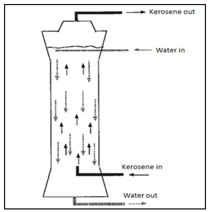 | Figure 1. Kerosene-water direct contact heat exchanger |
2. Theoretical Analysis
2.1. The Governing Parameters
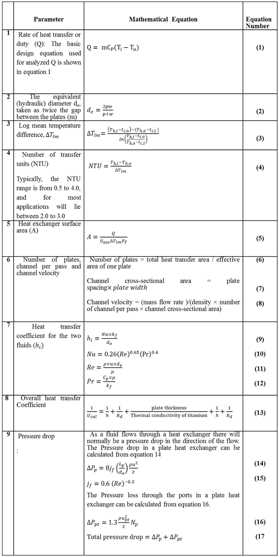
- Heat exchanger theory leads to the heat exchanger design equation that relates the overall heat transfer coefficient, heat transfer surface area, and log mean temperature difference, to the rate of heat transfer. To determine the rate of heat transfer or duty (Q), information about the inlet and outlet of the exchanger are needed, while no information about the internals are included. For the entire exchanger the rate of heat transfer is the total rate of heat transfer of the heating and cooling streams. In the recent work the heat transfer and the design characteristics of single phase direct contact heat exchanger were calculated based on heat exchanger design equations. The calculated parameters and the corresponding mathematical equations used in calculations are shown in appendix 1.
2.2. Heat Recovery from Single Phase (Kerosene-Water) System
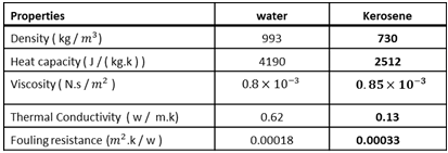
- The recent study deals with heat recovery from a direct contact heat exchanger used hot petroleum refinery product (Kerosene stream) as the heating fluid and water stream as cooling fluid, proposing that no phase changes in the fluid streams flowing through the exchanger. Rate of heat transfer and the heat exchanger design characteristics calculations were conducted based on data of physical properties of the fluids and the heat exchanger design parameters extracted from literature (Hill, 1950; Marsh, 1987; Kakac and Liu, 2002; Shah and Sekulic, 2003; Sinnott, 2005; Bengtson, 2010). The overall coefficient, light organic-water, is assumed to be 1736 W m-2°C-1 based on the data estimated from (Bengtson, 2010). Table 1 and 2 show the physical properties of the fluids and the heat exchanger design parameters respectively.
|
|

2.3. Statistical Analysis Using Statgraphics Plus for Windows Software
- The statistical analysis procedure of Statgraphics plus for Windows software (5.1 version) for experimental design and data treatment was used to optimize and model the effect of the operating variables of the heating fluid on rate of heat transfer (heat recovered). Response surface methodology (RSM) in conjunction with central composite rotatable design was performed. The RSM normally allow identifying the effects of operating parameters (independent variables Xi) on different responses Yj (dependent variables). A central composite design consisting of 16 experimental runs with two replicates at the center point was established. The mathematical empirical model applies is:
 | (1) |
 and
and  are the independent variable
  are the regression coefficients. The analyses of variance (ANOVA) were used to determine significant differences between the independent variables (p<0.05). Pareto chart was used to identify the impact of variables on various responses. The vertical line in the Pareto chart determines the effects that are statistically significant at 95% as confidence level (Raymond et al., 2016).
 2.3.1. Experimental Design
- In order to reduce the experimental trials required to carry out the effects for the main operating parameters (inlet temperature, outlet temperature, and mass flow rate) of kerosene, 3-component rotary central composite design was used; 16 experiments were designed included 2*3= 6 factorial points, 2*4=8 star point and 2 replicates for the central point. The experiments were performed randomly to minimize the effects of unexpected variability on the observed responses due to unusual responses. The coded and actual levels of independent variables used in experimental design are listed in Table 3.
|

3. Results and Discussion
3.1. Mathematical Analysis
- Improving and optimization of heat exchanger performance is associated with operating the heat exchanger within its designed and specified limits, also the operating parameters that can affect heat exchanger performance should be identified such that they are maintained and controlled at the designed point. Among the key operating parameters must be monitored are the feed material and heat exchanger operating temperatures. In the recent work the heat exchanger design parameters and the heat transfer characteristics were calculated. The effect of the heating fluid inlet temperature and its mass flow rate on direct contact heat exchanger design parameters (heat exchange surface area, number of plates, number of channels per pass and pressure drop), and on rate of heat transfer were investigated theoretically throughout nine cases. The spreadsheet results of the nine investigations are summarized in table 4. The cases (from 1 to 5) are investigated at constant average temperature of kerosene (70°C), and different mass flow for kerosene ranging from (25 to 45) kg/s, while, and the cases (1 and from 5 to 9) are estimated at constant mass flow rate of kerosene (25 kg/s) and different kerosene inlet temperature range (65-97.5°C). The investigated operating parameters were correlated with the heat exchanger design parameters and the heat recovered from the heat transfer process.
|

3.1.1. Effect of Kerosene Mass Flow Rate
- The estimated correlations for the effect of mass flow rate of kerosene at constant kerosene inlet temperature (70°C) are shown in Figures (2-6). An increase in mass flow rate of kerosene resulted in an increase in heat exchanger performance (heat recovered) as shown in Figure 2. The reason behind that is attributed to that high mass flow rate of kerosene will promote turbulence and good thermal contact/transfer. However, with higher values of flow rate, adequate importance should be given to heat exchanger design characteristics to achieving optimum performance. As seen, increasing kerosene flow rate is associated directly with increasing the contact surface area (Figure 3), increasing the number of plates (Figure 4), and number of channels per pass (Figure 5). Moreover, increasing kerosene mass flow rate resulted in increasing the pressure drop (Figure 6). It is well noticed that as a fluid flows through a heat exchanger there will normally be a pressure drop in the direction of the flow. The pressure drop is usually affected by type of flow (laminar or turbulent) and the passage geometry. The reason behind increasing the pressure drop with increasing kerosene mass flow rate may be due to the ununiformed flow rate distribution at high flow rate values. High pressure drop will lead to high velocity at the exit of the heat exchanger that resulted in erosion problems and increase the pumping costs. It is worthy to mention that the effectiveness of heat transfer is gauged by how well getting returns for what spending. Hence, the increased pressure gradient is usually outweighed by a decrease in required passage length so the overall pressure drop remains acceptable (Bassiouny and Martin, 1984).
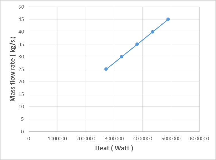 | Figure 2. Variation of kerosene mass flow rate with the heat recovered |
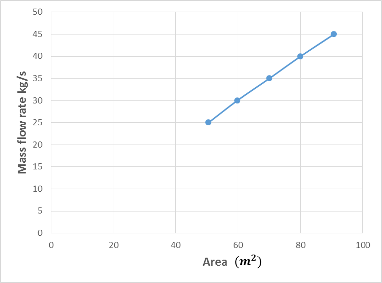 | Figure 3. Variation of kerosene mass flow rate with the surface area of the heat exchanger |
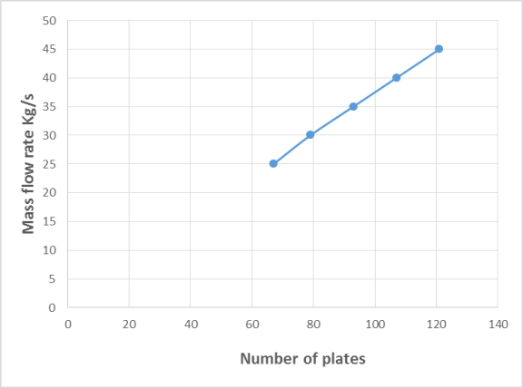 | Figure 4. Variation of kerosene mass flow rate with number of plates of the heat exchanger |
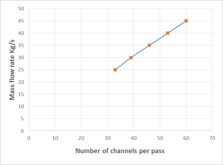 | Figure 5. Variation of kerosene mass flow rate with number of channels per pass |
 | Figure 6. Variation of kerosene mass flow rate with pressure drop |
3.1.2. Effect of Kerosene Inlet Temperature
- The estimated correlations for the effect of kerosene inlet temperature at constant kerosene mass flow rate (25) kg/s are shown in Figures (7-11). At constant mass flow rate of kerosene the heat recovered increases when kerosene temperature increases as shown in Figure 7. Generally, any alterations in the stream temperature will create a variation in the exchanger duty and log mean temperature difference (Dahran, 2017). When the heat exchanger is designed to operates at high kerosene inlet temperature, big heat exchangers with large areas (Figure 8), high number of plates (Figure 9) and channels per pass (Figure 10) are needed for efficient heat exchanger performance. On another hand as kerosene inlet temperature increases pressure drop decreases owing to decreasing the viscosity of kerosene with increasing kerosene inlet temperature. However, when the operating variables limits are exceeded, the design characteristics will show dramatic changes (Babu, 2004). Hence, reaching a good compromise is relevant to the perfect weighing of the factors against each other.
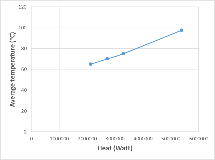 | Figure 7. Variation of kerosene temperature with amount of heat recovered |
 | Figure 8. Variation of kerosene temperature with surface area |
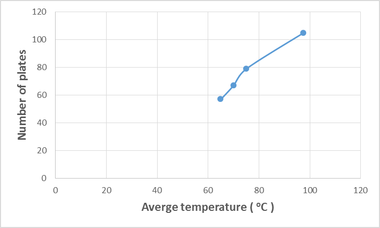 | Figure 9. Variation of kerosene temperature with number of plates |
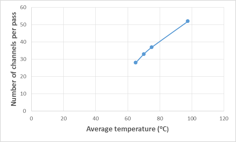 | Figure 10. Variation of kerosene temperature with the number of channels per pass |
 | Figure 11. Variation of kerosene temperature with pressure drop |
3.2. Response Surface Analysis Results
- Response Surface Methodology was applied in order to model and optimize the effect of kerosene operating variables including inlet temperature, outlet temperatures and mass flow rate on the heat could be recovered from the heat transfer process. An experimental design was adopted with 16 experiments to study the effect of kerosene inlet temperature ranged (58.18-91.8)°C, kerosene outlet temperature ranged (26.59-43.4)°C, and kerosene mass flow rate ranged (24.88-50.1) kg/s on rate of heat transfer (heat recovered). The heat recovered corresponding to each experiment was calculated theoretically and applied to the software for analysis. Table 5 listed the levels of independent variables and the response for the 16 runs.
|

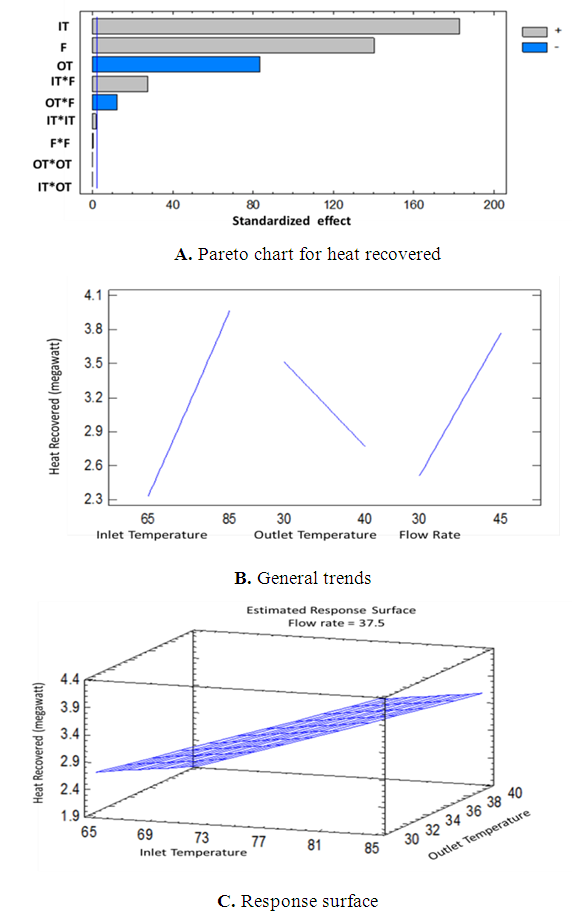 | Figure 12. Pareto chart (A), general trends (B), response surface (C) for the effect of kerosene inlet temperature, outlet temperature and flow rate on the heat recovered |
 | (2) |
|
4. Conclusions
- Studies related to the applications of recoverable heat to produce additional power using direct contact heat exchangers are very important from economic and environmental point of view. In oil industry, direct contact heat exchangers are important heat source for providing additional power. Waste heat recovery could take place through a thermal approach that uses the hot temperature oil streams to heat up water and partially fulfill heating or hot water needs of the industrial site. To recover heat from these heat exchangers efficiently, the heat exchangers are needed to be designed in such a way that it can handle the heat load with reasonable size, weight and pressure drop. Upon investigating how physical, design and heat transfer characteristics of single phase kerosene-water direct contact heat exchange system influenced the heat exchangers effectiveness, the design parameters were of significant impact. Also, Statgraphics plus software seemed very applicable to optimize and model the amount of heat recovered as well as kerosene operating variables. With an optimum design of the heat exchanger an optimum heat value (6.88 megawatt) could be recovered when kerosene enters the heat at 91.18°C and flow rate of 50.1 kg/s.
|
|
