-
Paper Information
- Paper Submission
-
Journal Information
- About This Journal
- Editorial Board
- Current Issue
- Archive
- Author Guidelines
- Contact Us
International Journal of Instrumentation Science
p-ISSN: 2324-9994 e-ISSN: 2324-9986
2017; 6(1): 1-7
doi:10.5923/j.instrument.20170601.01

Development of Smart Sensing Unit for Vibration Measurement by Embedding Accelerometer with the Arduino Microcontroller
 Abstract
 Reference
 Full-Text PDF
 Full-text HTML
Viral K. Patel1, Maitri N. Patel2
1Control and Instrumentation Department, Gujarat State Fertilizers and Chemicals Ltd, Vadodara, India
2Student (M. Tech.-Control & Automation), Nirma University, Ahmedabad, India
Correspondence to: Viral K. Patel, Control and Instrumentation Department, Gujarat State Fertilizers and Chemicals Ltd, Vadodara, India.
| Email: |  |
Copyright © 2017 Scientific & Academic Publishing. All Rights Reserved.
This work is licensed under the Creative Commons Attribution International License (CC BY).
http://creativecommons.org/licenses/by/4.0/

In this paper, we have described a novel smart sensing unit for vibration measurement and machinery condition monitoring. Here we have embedded accelerometer with the arduino microcontroller board. Where microprocessor-based smart sensor shall collect 3-D vibrations; and these stored data in microcontroller can be sent to third party devices (Laptop, PC etc.) for further signal analysis. Analytical approaches have demonstrated that vibration monitoring has tremendous potential in detecting localized defects in the machines. When mounted in proximity of a bearing housing (a general case), these module can collect the Stationary as well as non-stationary signature data of vibration of bearing housing reliably. Since, most vibration sensors are mounted in proximity of bearing housings (based on mechanical impedance considerations); bearing fault detection techniques can be implemented for online bearing condition monitoring. This module can be easily deployed for different rotating machines for vibration monitoring purposes. Arduino board is utilized for collecting data from sensor as data acquisition module; which consists of ATMega328P microcontroller having 16 MHz clock speed, hence enabling us to capture high frequency signals from accelerometer.
Keywords: Smart sensor, Vibration monitoring, Signature data, Accelerometer, Arduino, LabVIEW
Cite this paper: Viral K. Patel, Maitri N. Patel, Development of Smart Sensing Unit for Vibration Measurement by Embedding Accelerometer with the Arduino Microcontroller, International Journal of Instrumentation Science, Vol. 6 No. 1, 2017, pp. 1-7. doi: 10.5923/j.instrument.20170601.01.
Article Outline
1. Introduction
- A Reliable online machinery condition monitoring system is very useful to a wide array of industries to recognize an incipient machinery defect so as to prevent machinery non-fatal failure, malfunctions, or even catastrophic failures. An early fault warning can enable the establishment of a predictive maintenance program [1], which is critical to those machines (e.g., airplanes, power turbines, and chemical engineering facilities) to which an unexpected shutdown would cause serious economic or environmental consequences [2, 3]. Fault detection can be conducted based on information carriers such as the acoustic emission, vibration frequency waveform, oil analysis, temperature variation, etc. However early fault warning based on vibration signal has proven track record of preventing catastrophic failures; hence we will discuss about that in detailed manner in this paper [1]. Vibration is a mechanical oscillation around a reference point and defines the movement of a mechanical system [2]. The vibration is characterized by amplitude, speed, acceleration and frequency spectrum. The measures which characterize the movement (vibration) of the system that is the displacement, speed and acceleration are defined according to the relations (1), (2) and (3):
 | (1) |
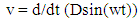 | (2) |
 | (3) |
2. Description of the Smart Sensing Unit
- The developed smart sensor is a microprocessor-based sensing unit, which can collect 3-D vibrations. As shown in figure 1 components of system have been delineated; here, vibration sensor and signal amplifier are part of ADXL335 circuit in which signal measurement and amplification is carried out to obtain low amplitude signal faithfully and to avoid any loading effect. Here, amplified signal is collected by arduino micro-controller and these acquired data can be sent via serial communication protocol to any third party devices. In following we will discuss each component of Smart sensing unit in detail as described in figure 1.
 | Figure 1. The components of the system |
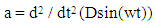
2.1. Vibration sensing and amplification by ADXL335
- The ADXL335 is a small, thin, low power, complete 3-axis accelerometer with signal conditioned voltage outputs as shown in figure 2. It measures acceleration with a full-scale range of ±3 g (1 g = 9.8 m/s2, g is gravitational constant). It can measure the static acceleration of gravity in tilt-sensing applications, as well as dynamic acceleration resulting from motion, shock, or vibration. The user selects the bandwidth of the accelerometer using the Cx, Cy, and Cz capacitors at the Xout, Yout, and Zout pins. Bandwidths can be selected to suit the application, with a range of 0.5 Hz to 1600 Hz for the X and Y axes, and a range of 0.5 Hz to 550 Hz for the Z axis.
 | Figure 2. Vibration measurement and amplification |
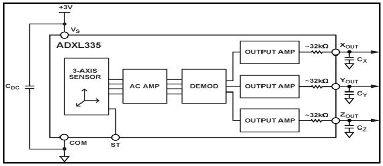
 | Figure 3. Silicon wafer based sensor |
2.1.1. Three Dimensional Measurements
- The ADXL335 uses a single structure for sensing the X, Y, and Z axes. As a result, the three axes’ sense directions are highly orthogonal and have little cross-axis sensitivity. Mechanical misalignment of the sensor die to the package is the chief source of cross-axis sensitivity. Mechanical misalignment can, of course, be calibrated out at the system level.
2.1.2. Performance
- Rather than using additional temperature compensation circuitry, innovative design techniques ensure that high performance is built in to the ADXL335. As a result, there is no quantization error or non monotonic behavior, and temperature hysteresis is very low (typically less than 3 mg over the −25°C to +70°C temperature range).
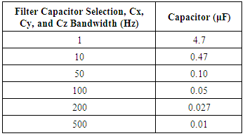
2.1.3. Setting the Bandwidth Using Cx, Cy, and Cz
- The ADXL335 has provisions for band limiting the Xout, Yout, and Zout pins. Capacitors must be added at these pins to implement low-pass filtering for anti-aliasing and noise reduction. The equation for the 3 dB bandwidth is,F3 dB = 1 / (2π(32 kΩ) × C(X, Y, Z))Or more simply,F3 dB = 5 μF/C(X, Y, Z)The tolerance of the internal resistor typically varies as much as ±15% of its nominal value (32 kΩ), and the bandwidth varies accordingly. A minimum capacitance of 0.0047 μF for Cx, Cy, and Cz is recommended in all cases.
|
2.1.4. Noise Consideration
- The ADXL335 output is ratio metric; therefore, the output sensitivity (or scale factor) varies proportionally to the supply voltage. At Vs = 3.6 V (Vs = Supply voltage), the output sensitivity is typically 360 mV/g. At Vs = 2 V, the output sensitivity is typically 195 mV/g. However, the output noise is not ratio metric but is absolute in volts; therefore, the noise density decreases as the supply voltage increases. This is because the scale factor (mV/g) increases while the noise voltage remains constant. At Vs = 3.6 V, the X-axis and Y-axis noise density is typically 120 μg / √Hz, whereas at Vs = 2 V, the X-axis and Y-axis noise density is typically 270 μg/√Hz. Hence noise signal interference can be avoided by using high supply voltages.
2.2. Vibratory Signal Acquisition Using Arduino
- A microcontroller based data acquisition board (ARDUINO-DAQ) is used here with two objectives:• To use an independent data acquisition system with data buffering feature to reduce the Computation load on the main central fault diagnostic system.• To have a dedicated hardware that can be installed close to the motor and can sustain the industrial harsh environment.The Arduino Uno ("Uno" means one in Italian) is a microcontroller board based on the ATmega328 as shown in figure 4. It has 14 digital input/output pins (of which 6 can be used as PWM outputs), 6 analog inputs, a 16 MHz ceramic resonator, a USB connection, a power jack, an ICSP (In circuit serial programming) header, and a reset button. It contains everything needed to support the microcontroller; simply connect it to a computer with a USB cable or power it with AC-to-DC adapter or battery to get started. Also an advantage of using the Uno is that the chip used in it can be replaced for relatively cheap cost. UNO board is the very first of the Arduino boards and even though there are some advanced boards available; for this project, the UNO board will be enough. Here, Interfacing of ADXL335 accelerometer with Arduino is straightforward. And the parts required for this process are the Arduino board, ADXL335 accelerometer, connecting wires, and USB cable to connect Arduino board to computer.
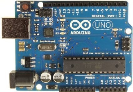 | Figure 4. Arduino Board with In circuit serial programming (ICSP) |
2.2.1. Process for Circuit Building
- Accelerometer has 5 pins and all of these are connected to Arduino board. First connect the GND (ground) pin of ADXL335 to Arduino’s GND. Then connect the VCC (supply voltage) of ADXL335 to Arduino’s 5V, then X to Arduino's analog pin A5, Y to Arduino’s analog pin A4, and Z to Arduino’s analog pin A3. After performing above wiring final product would be as shown in figure 5. Here Refrnce voltage for Analog to dgital conversion would be 5V. The Arduino Uno has 6 analog inputs, labeled A0 through A5, each of which provide 10 bits of resolution (i.e. 1024 different values). By default they measure from ground to 5 volts, though is it possible to change the upper end of their range using the Aref pin and the analogReference() function.
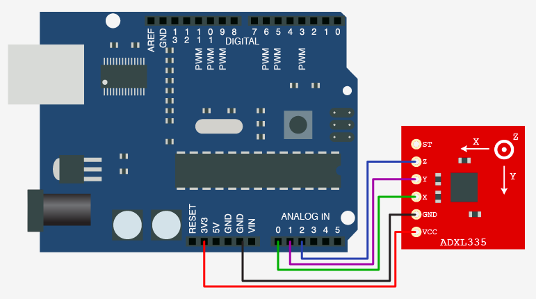 | Figure 5. Interfaced Arduino with ADXL335 |
3. Programming in Arduino
- After interfacing of Arduino with accelerometer next step is programming of ATmega328 controller via USB to serial programmer. The ATmega328 on the Arduino Uno comes pre-burned with a boot-loader that allows you to download new code to it without the use of an external hardware programmer. Following is the sample program boot loaded to controller for fetching the sensor data and transferring it to the PC, Laptop etc./*This example code is in the public domain.*/// these constants describe the pins. They won't change:const int groundpin = 18; // analog input pin 4 – ground(A4)const int powerpin = 19; // analog input pin 5 – voltage(A5)const int xpin = A3; // x-axis of the accelerometer(A3)const int ypin = A2; // y-axis(A2),ST(A0)const int zpin = A1; // z-axis (only on 3-axis models)(A1)void setup(){// initialize the serial communications:Serial.begin(19200);// Provide ground and power by using the analog inputs as normal// digital pins. This makes it possible to directly connect the// breakout board to the Arduino. If you use the normal 5V and// GND pins on the Arduino, these lines can be removed.pinMode(groundpin, OUTPUT);pinMode(powerpin, OUTPUT);digitalWrite(groundpin, LOW);digitalWrite(powerpin, HIGH);}void loop(){// print the sensor values:Serial.print(analogRead(xpin));// print a tab between values:Serial.print(analogRead(ypin));// print a tab between values:Serial.print(analogRead(zpin));Serial.println();// delay before next reading:delay(100);}The Arduino software includes a serial monitor which allows monitoring of simple textual data to be sent to and from the Arduino board. The Arduino Uno has a number of facilities for communicating with a computer, another Arduino, or other microcontrollers. The ATmega328 provides UART (Universal asynchronous receiver transmitter) TTL (Transistor transistor logic) serial communication, which is available on digital pins 0 (RX) and 1 (TX). An ATmega16U2 controller on the board channels this serial communication over USB and appears as a virtual com port to software on the computer. Now next part is to transfer these data to third party software such as LabVIEW (Laboratory Virtual Instrument Engineering Workbench) for vibration analysis purposes [4].
3.1. Vibration Signal Analysis Using LabVIEW
- Any kind of serial data available on computer port can be captured by LabVIEW with the help of National Instrument’s (NI) VISA drivers (Virtual Instrument Software Architecture). The Virtual Instrument Software Architecture (VISA) is a standard for configuring, programming, and troubleshooting instrumentation systems comprising GPIB, VXI, PXI, Serial, Ethernet, and/or USB interfaces. Here data dumped on serial port of Arduino will be in the range of 0-1024 different values as it is digital values (Values after 10-bit Analogue to digital conversion). Therefore either you can observe the vibration signal amplitude in 0-1023 range or you can convert it back to 0-5 volt range using arithmetic functions available in labVIEW. Once you get this serial data from Arduino then it is up to us to utilize it in optimum way for analysis. Because, LabVIEW is able to construct waveform based on serial data available; it is able to process this signal rigorously; LabVIEW contains signal processing palette which consists of FFT (Fast Fourier Transform) and spectral analysis tools. LabVIEW and its analysis VI library provide a complete set of tools to perform Fourier and spectral analysis [4]. The Fast Fourier Transform (FFT) and Power Spectrum VIs are optimized, and their outputs adhere to the standard DSP format.FFT is a powerful signal analysis tool, applicable to a wide variety of fields including spectral analysis, digital filtering, applied mechanics, acoustics, medical imaging, modal analysis, numerical analysis, seismography, instrumentation, and communications. The LabVIEW analysis VIs, located on the Signal Processing palette, maximize analysis throughput in FFT-related applications [4]. However it completely depends on user to manipulate FFT and power spectrum results to extract useful frequency information.
3.1.1. Fast Fourier Transform
- The fast Fourier transform maps time-domain functions into frequency-domain representations.
3.1.2. Power Spectrum
- Power Spectrum analysis, which is closely related to the FFT, to calculate the harmonic power in a signal.
4. Communication between Arduino & LabVIEW
- LIFA stands for LabVIEW Interface For Arduino. This is an extension of LabVIEW (compatible with version 2009) that allows you to control an Arduino compatible card from LabVIEW. In this article we proposed an installation of LIFA because for the moment we did not find much resource on the internet on this subject. This article is not a presentation of LabVIEW or Arduino (you have plenty of resources for this on the web) but a joint use of LabVIEW and Arduino.
4.1. Software
- For communication we will require VISA drivers with NI LabVIEW to run the serial port, VI packet manager, LIFA package available on web; now install all soft wares in the same order as mentioned. Next part is to install LIFA firmware on arduino board.
4.1.1. Installing the LIFA Firmware on the Arduino Board
- The LIFA firmware is available after installation in the "C: \ Program Files \ National Instruments \ LabVIEW 2011 \ vi.lib \ LabVIEW Interface for Arduino \ Firmware \ LVIFA_Base" directory . The sketch "LVIFA_Base.ino", it is this sketch that we will compile and transfer in the Arduino board. The "LabVIEWInterface.ino", it contains the implementation of all the functions used by LabVIEW to interact with the Arduino board. The file of inclusion "LabVIEWInterface.h", this file of header is particularly interesting since it is it that contains the "define" that you can modify to adapt LIFA. DEFAULT BAUDRATE: The transmission speed of the serial port. Indeed, LabVIEW communicates with the Arduino card via a serial port, by default the speed is 115200 bauds, but if you use a wireless serial link (XBee or Bluetooth), it may be necessary to lower the transmission speed to make the dialogue.COMMAND LENGTH: The number of bytes transmitted at one time by a LabVIEW command. By default, this value is 15. If this is insufficient for your project, you must change it here and on the LabVIEW diagram.Now we will execute sample VI in LabVIEW for serial read/write function for communicating with Arduino board. This sample VI can be seen as shown in figure 6.
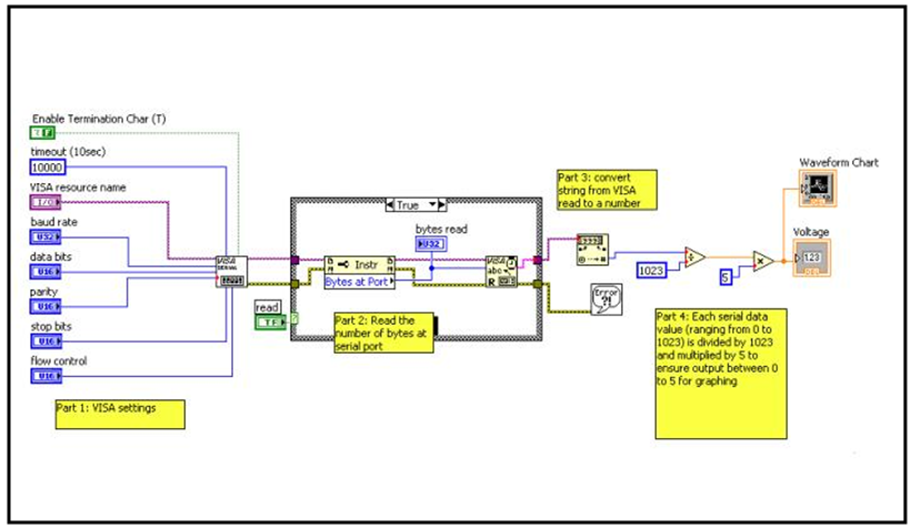 | Figure 6. Serial read/write VI in LabVIEW |
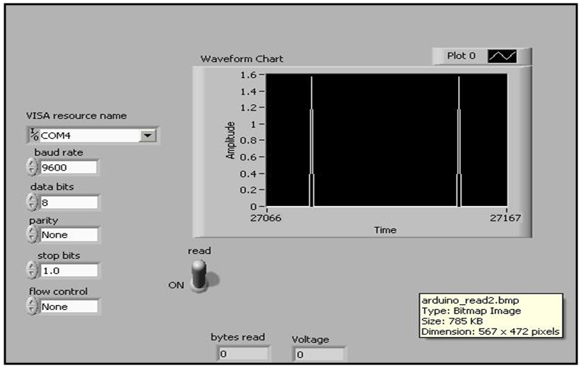 | Figure 7. Vibration signal waveform |
5. Conclusions
- By this kind of vibration sensing module system, we can make sure that fidelity of vibration measurement is maintained and hence we can make reliable decision on preventive maintenance practices for various machineries in industries. These kinds of full-proof preventive maintenance programs prevents unnecessary breakdown of heavy rotating equipments which eventually results in significant down-time of process plants. Hence, cost will be saved; time and man-power resources will also be saved. So, smart sensing module ensures robustness and faithfulness of vibration measurement.