-
Paper Information
- Paper Submission
-
Journal Information
- About This Journal
- Editorial Board
- Current Issue
- Archive
- Author Guidelines
- Contact Us
International Journal of Instrumentation Science
p-ISSN: 2324-9994 e-ISSN: 2324-9986
2014; 3(2): 13-16
doi:10.5923/j.instrument.20140302.01
Instrumentation Geophysics: Design and Construction of a DC Variable Power Supply
 Abstract
 Reference
 Full-Text PDF
 Full-text HTML
1Department of Physical and Geosciences, Godfrey Okoye University, Ugwu-omu Nike, Nigeria
2Department of Geology, Anambra State University, Uli, Nigeria
Correspondence to: Onuorah L. O., Department of Physical and Geosciences, Godfrey Okoye University, Ugwu-omu Nike, Nigeria.
| Email: |  |
Copyright © 2014 Scientific & Academic Publishing. All Rights Reserved.
This work demonstrates the design and implementation of a 3, 6, 9, 12 and 24 Volts switching mode power supply system that replaces battery as a major source of direct current (DC) voltage for electronic equipment that can be used to energize electrodes, in geophysics field work that involves electrical resistivity surveys, seismographic and magneto-telluric surveys. The switching mode output of a variable power supply system produces direct voltages of 3, 6, 9, 12, and 24 Volts that are selected by a multi-output switch. These voltages are stepped down from a 220 Volt alternating current (AC) main terminal by an auto (variable taps) transformer and thereafter rectified and smoothened. This smoothing process by a bridge rectifier converts AC to direct current (DC) and filters off the associated impurities and ripples. The capacitor used for each stage has the rating of 2200microfarad (µf) and 35Volts.
Keywords: Direct current, Alternating current, Multi-output switching, Voltage and capacitive filters
Cite this paper: Onuorah L. O., Nwozor K. K., Instrumentation Geophysics: Design and Construction of a DC Variable Power Supply, International Journal of Instrumentation Science, Vol. 3 No. 2, 2014, pp. 13-16. doi: 10.5923/j.instrument.20140302.01.
1. Introduction
- As discussed in the sequel, a regulated power supply is indispensable in powering or precision equipment operations. Joshua DuBois [4] defined electrical current as the time rate of change of charge flow in a circuit. Williams, O. A., [6] suggested that since the energy from the wall outlet is practically unlimited, it can be converted from its alternating current (AC) to direct or steady current (DC), and tailored to provide the voltage suitable for electronic equipment. This can be achieved in a DC power supply unit (PSU), and the PSU used in the laboratory for experiments is termed a laboratory bench supply. It can be designed as a variable power supply unit that can supply either a uni-polar or bi-polar power to the load (Shoewu et al., [5]). In most countries the electricity from the power grid to homes, industries and laboratories is transmitted and distributed in AC form, while most electronic equipment directly use the suitable means of converting the alternating supply to direct current therefore becomes indispensable. An alternating current is a current that varies in magnitude and direction with time (Fig. 1a) and a direct current is a current that maintains a constant magnitude as it flows through a wire without change in direction with time (Fig. 1b).
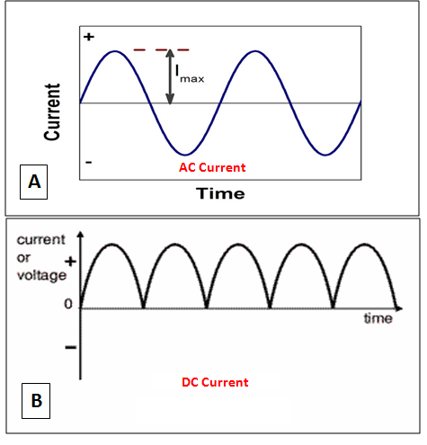 | Figure 1. Schematic representation of AC (A) and DC (B) Currents (Source: Williams, 1995) |
2. Design and Construction
- The switching mode power supply is made up of a number of stages. These stages are the transformer, the voltage selector, full-wave bridge rectifier and finally the filtering and smoothening circuit. The transformer operation consists of step-up and step-down modes. The step-up mode utilizes a high voltage secondary and low voltage primary. On the other hand, the step-down mode which this project is concerned with uses a low-voltage secondary and high voltage primary as illustrated in Fig. 2.
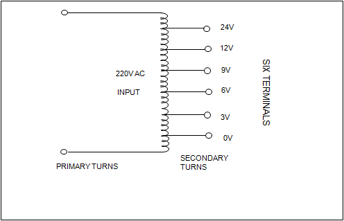 | Figure 2. Design of a variable auto-transformer |
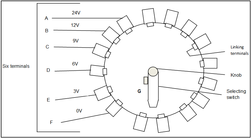 | Figure 3. Switch arrangement |
 | Figure 4. Full-wave bridge rectifier and smoothening circuit |
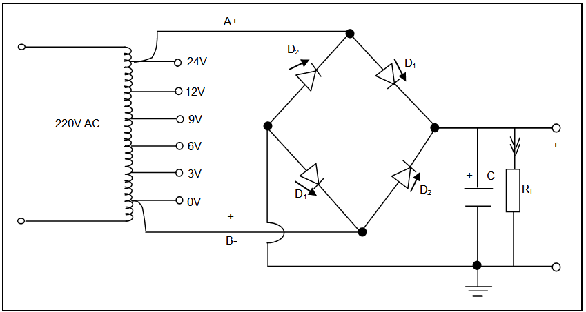
 The S.I units of capacitance, charge and potential difference are the farad (f), Coulomb (C) and Volts (V), respectively. The voltage rating of the capacitor must be much greater than the output voltage; else the voltage will rupture the capacitor. Also, the bigger the capacitance of the capacitor the better the result hence the capacitor used in the project is rated 2200 microfarad (µf) and 35V. Figure 4 shows the capacitor placed in parallel with the load resistor, RL. The power supply filter stores energy when the current is high and gives it up when the current is low. This results in smoothing out the variations in current and as a result provides almost steady state DC that maintains a steady flow of power. The rectification and filtering stages were taken care of by a good combination of bridge rectifier and capacitor as shown in Fig. 4. The complete circuit diagram is shown in Fig. 5.
 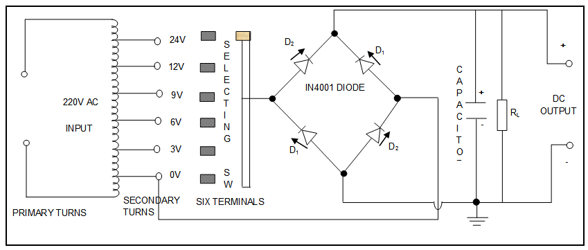 | Figure 5. Complete circuit diagram for the power supply system |
3. Conclusions
- This work has successfully presented a switching mode of a variable power supply system. It produces DC voltages of (3, 6, 9, 12 and 24) Volts that replace battery as its major source for electronic equipment used in the field, industries, laboratories and houses. The step-down transformer function is to steps down the mains voltages from 220V to the required DC outputs terminals 3, 6, 9, 12 and 24 Volts (fig. 2). Figure 3 shows the switch as the terminals selector. An important function of a rectifier diode is to convert an alternating current (AC) into a direct current (DC) by a process known as rectification. It allows the passage of electric current in one direction and blocks from the other (fig. 4). The significant of a capacitor in rectification is to block DC while permitting AC to pass through and to smooth the top of the rectified DC output. This variable power supply system is very simple in design with few components and can be built with ease into a complete circuit diagram for the power supply system of any desired appliance.