-
Paper Information
- Paper Submission
-
Journal Information
- About This Journal
- Editorial Board
- Current Issue
- Archive
- Author Guidelines
- Contact Us
International Journal of Instrumentation Science
p-ISSN: 2324-9994 e-ISSN: 2324-9986
2014; 3(1): 8-11
doi:10.5923/j.instrument.20140301.02
Differential Temperature Controller for the Measurement of Thermoelectric Power on Small Samples
 Abstract
 Reference
 Full-Text PDF
 Full-text HTML
Ravindrapal M. Joshi
Department of Electronics, M. B. Patel Science College, Anand-388 001, Gujarat
Correspondence to: Ravindrapal M. Joshi, Department of Electronics, M. B. Patel Science College, Anand-388 001, Gujarat.
| Email: |  |
Copyright © 2014 Scientific & Academic Publishing. All Rights Reserved.
A low cost simple and versatile Seebeck coefficient ‘S’ measurement setup is fabricated. The fabricated setup can measure values of Seebeck coefficient ‘S’ with variation in temperature. The temperature can be varied from 25°C to 300°C. The setup can measure the value of S in the said temperature range for small samples. The compact setup has two heaters to raise overall temperature of the sample from 25°C to 300°C. The auxiliary heaters maintain the temperature gradient. The set overall sample temperature and temperature gradient is maintained by controller circuit and other ancillary circuits. To reduce error in Seebeck measurements, the temperature gradient ΔT can be varied from 1 to ± 10°C. The measured Seebeck coefficient ‘S’ variation with temperature for four single crystal samples using the fabricated setup is presented.
Keywords: Differential temperature controller, Seebeck coefficient, Semiconductors
Cite this paper: Ravindrapal M. Joshi, Differential Temperature Controller for the Measurement of Thermoelectric Power on Small Samples, International Journal of Instrumentation Science, Vol. 3 No. 1, 2014, pp. 8-11. doi: 10.5923/j.instrument.20140301.02.
Article Outline
1. Introduction
- The measurement of Seebeck coefficient as a function of temperature is one of the most significant methods for investigating electronics properties of solids. In fundamental, the Seebeck coefficient ‘S’ provides useful information about the mechanisms of electrical transport. The quantity S can be used to determine the mobility ratio, the concentration of majority carriers, the position of Fermi level, scattering mechanism, etc, and it has been used for the study of electrical transport properties of samples by many investigators [1-4]. The polarity of S indicates the types of dominant carriers or the type of dominant electric conduction.The author has developed a simple instrument: differential temperature controller, to undertake measurements of Seebeck coefficient in the temperature range 25°C to 300°C. The controller controls not only the overall temperature but also maintains the temperature gradient (0°C to 10°C) between the two ends of the sample. The instrument is very compact, low power and easy to operate.
2. Operating Technique
- The sketch of the experimental setup is shown in Figure 1. It consists of two blocks. Block – 1: Sample holder with heaters and pick up probes and Block – 2: electronic circuits controlling temperature and temperature gradient across the sample. The sample holder consists of two low power heaters A and B (15W each). Temperature T of the heater A is measured by thermocouple TC1 and the temperature difference ΔT between A and B is measured by differential temperature sensor (TC2). Both the thermocouples are of K type. The sample under investigation is mounted directly on the heaters and is held by two pick up probes which are of copper (or stainless steel). The probes are made of copper or stainless steel so that they are a good conductor of electricity and measures the developed electrical signals at the sample surface where the junction if formed between the probe and the sample. Thus these probes measures the Seebeck voltage developed across the two ends of the sample.
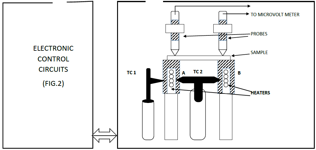 | Figure 1. Experimental system |
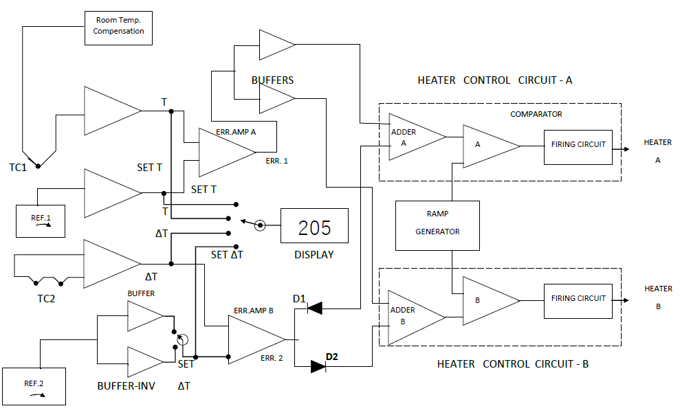 | Figure 2. Block diagram of the control circuit |
3. Results and Conclusions
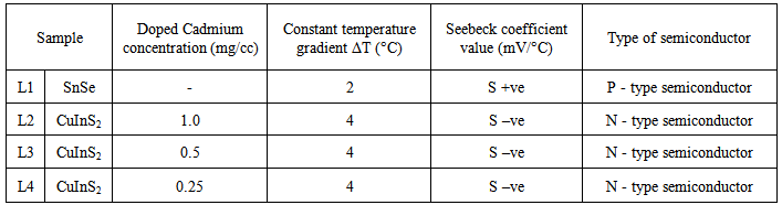
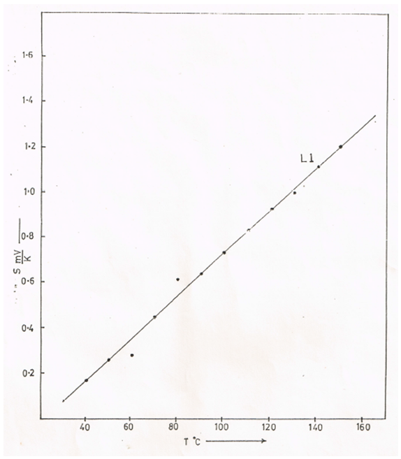
- As a test case of the fabricated setup, Seebeck coefficient S measurements were carried out on two samples, tin monoselenide (SnSe) and Cadmium doped copper indium disulphide (CulnS2) single crystals. The developed voltage across the probes was measured using digital voltmeter (Meco) connected externally. The results are shown in Figures 3 and 4. The brief of the samples employed, experimental conditions maintained and the obtained results are tabulated in Table 1.
|
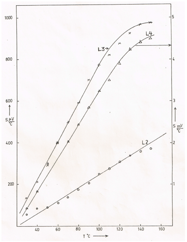 | Figure 3. Seebeck coefficient verses temperature in Cd doped CuInS2 crystals |
 | Figure 4. Seebeck coefficient vs temperature in SnSe single crystal |
4. Future Scope for Improvements
- The fabricated setup has future scope of improvement. The following are some of the improvements possible.1. The complete setup can be enclosed in a transparent case so that external atmospheric variation does not affect the measurements.2. In the present setup for reducing the stray thermopower variation in the temperature gradient from 1°C to 10°C is possible. Even further accuracy in measurement and reduction in the stray thermopower, change in the sign of the temperature gradient ΔT should be made.