-
Paper Information
- Next Paper
- Paper Submission
-
Journal Information
- About This Journal
- Editorial Board
- Current Issue
- Archive
- Author Guidelines
- Contact Us
International Journal of Instrumentation Science
p-ISSN: 2324-9994 e-ISSN: 2324-9986
2013; 2(1): 1-5
doi:10.5923/j.instrument.20130201.01
Analysis of Detector-Source Distance and Detector Bias Voltage for Time Resolution of Plastic Scintillation Detectors
 Abstract
 Reference
 Full-Text PDF
 Full-text HTML
E. E. Ermis, C. Celiktas
Ege University, Faculty of Science, Physics Department, 35100, Bornova, Izmir, Turkey
Correspondence to: E. E. Ermis, Ege University, Faculty of Science, Physics Department, 35100, Bornova, Izmir, Turkey.
| Email: |  |
Copyright © 2012 Scientific & Academic Publishing. All Rights Reserved.
The effects of the source-detector distance, the detector bias voltage variation and collimator usage on the time spectra of 133Ba and 207Bi calibration sources were investigated through a spectrometer which was consisted of a BC400 type general purpose plastic scintillation detector. Constant fraction timing method was used to test these effects on the time resolution values. Optimum source-detector distance and bias voltage values with and without collimator were determined for the optimum time resolution. It was concluded that the source to detector apart, the applied bias voltage to the used detector and the collimator usage were quiet effective parameters in coincidence timing experiments.
Keywords: 133Ba, 207Bi, Constant Fraction Timing Method, Time Resolution
Cite this paper: E. E. Ermis, C. Celiktas, Analysis of Detector-Source Distance and Detector Bias Voltage for Time Resolution of Plastic Scintillation Detectors, International Journal of Instrumentation Science, Vol. 2 No. 1, 2013, pp. 1-5. doi: 10.5923/j.instrument.20130201.01.
1. Introduction
- Timing measurement focuses on the determination of the time when a particular event has happened (i.e., a charged particle has crossed the detector), with a certain accuracy. The information on the energy associated with the event has a lesser priority or may even be disregarded. This fact fundamentally changes the way timing radiation systems are designed and optimized[1].Several different nuclear radiation detectors are used in timing experiments: scintillation counters with organic and NaI(Tl) scintillators, Cherenkov detectors, multiwireproportional chambers, semiconductor detectors. Scintillation counters with organic scintillators, however, are still superior to produce the best time resolution, as well as to be used in a variety of different applications.The time resolution of scintillation counters is generally determined by the method used in the so-called delayed-coincidence technique which is widely applicable for the measurements of short nuclear life-times. The time resolution of a timing system can be determined by measuring the distribution of the time delays between prompt events. The figure of merit of a system is usually characterized by the full width at half maximum (FWHM)[2].The premium plastic scintillators such as BC400 are the most economical as well as their highest light output[3]. The most common and widely used plastics are polyvinyltoluene, polyphenylbenzene and polystyrene. Plastics offer an extremely fast signal with a decay constant of about 2-3 ns. Because of this fast decay, the finite rise time cannot be ignored in the description of the light pulse[4].Using NaI(Tl) scintillation detector, time spectrum of 22Na was obtained by Nutt et al.[5]. Time spectrum of mixed radioactive alpha source (239Pu, 241Am and 244Cm) was given by means of multichannel plates (MCPs) and Si detectors by Sharma et al.[6]. Kawada et al.[7] presented time spectra of 60Co at different temperatures. Optimization of time resolution of a general purpose plastic scintillation detector through leading edge timing method was investigated by Ermis and Celiktas[8]. Ermis and Celiktas[9] carried out a study about time resolution investigations for general purpose plastic scintillation detectors in different thicknesses. Parnham and Eissler[10] depicted the time spectrum of 22Na radioisotope via a CdZnTe detector.Since the time resolution is a critical parameter for timing measurement setups, a spectrometer was constructed by using a BC400 type plastic scintillation detector. Time spectra of 133Ba and 207Bi radioisotopes were obtained for the determination of best time resolution by means of constant fraction timing technique. Optimization of time resolution of this type detector was carried out by depending on the source-detector distance and the detector bias voltage variation together with collimator effect.
2. Experiments
- 133Ba and 207Bi calibration sources with the activities of 3.5 x10⁵ Bq were used in this work. Their half-lives are 10.51 and 31.55 y, respectively[11]. The thicknesses and the diameters of the sources were 0.3 and 2.5 cm, respectively. The sources were placed in various distances far away from the detector active surface, perpendicularly to the detector normal direction.A Bicron BC400 type (equivalent to NE102A) plastic scintillation detector with 3 mm thickness and 3 inch diameter was used because this type plastic scintillator is preferred for general purpose radiation measurement applications[3].Constant fraction timing method, which is one of the timing methods, was used in this work. Probably the most efficient and versatile method available today is the constant fraction triggering technique[4, 12, 13]. In this method, a logic signal is generated at a constant fraction of the peak height to produce an essentially walk-free timing signal. The basis for this idea arose from empirical tests which showed the existence of an optimum triggering level for the best timing resolution. Depending on the type of signal, this level occurs at a certain fraction of the pulse height independent of the amplitude[4]. The principle of constant-fraction timing can be found in[4, 12, 13]. Block diagram of the used spectrometer is given in Fig. 1.
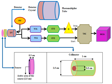 | Figure 1. Block diagram of the used spectrometer |
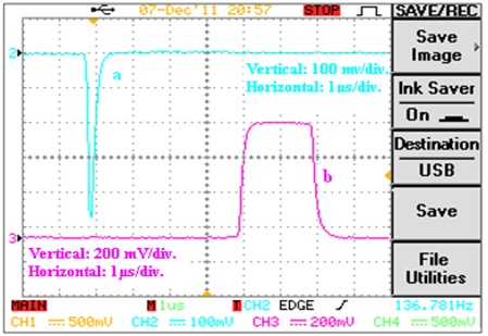 | Figure 2. Signal shapes of (a) TFA and (b) TAC outputs |
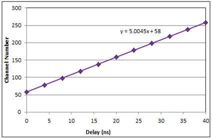 | Figure 3. Time calibration graph (fitted time calibration=195.3125 ± 0.0051 ps/ch) |
3. Results
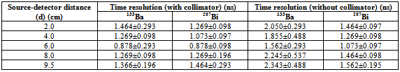
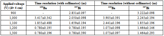
- To find out optimum time resolution according to the variation of detector-source apart, we collected time spectra of the sources at various detector-source distances without and with collimator. Best time resolution values were obtained at 6 cm from the measurements as given in Table 1. Since optimum time resolution results were obtained in the detector-source apart of 6 cm for the used radioisotopes without and with collimator, they were placed in turn at 6 cm from the detector window for the optimization of detector bias voltage at this distance. We changed the applied voltage to the detector from 900 V to 1,300 V. It was observed that the time resolution values were saturated at 1,200 V-1,300 V as summarized in Table 2.
|
|
4. Conclusions
- The effects of the source-detector distance and the detector bias voltage variation on the time spectra of 133Ba and 207Bi calibration sources were investigated through a spectrometer consisted of a BC400 type plastic scintillation detector by means of constant fraction timing method. Optimum source-detector distance and bias voltage values were determined for the best time resolution.Experimental results showed that the optimum time resolution for both radioisotopes without and with collimator were obtained when the source-detector distance was set to 6 cm as shown in Table 1. It can be deduced from this result that the detector to source distance is quite effective on time resolution. This result points out that the effect of the detector-source distance on time resolution should be taken into consideration especially in coincidence measurements.Effect of the variation of the detector bias voltage to the time resolution was also investigated. In order to analyze this effect, both radioisotopes without and with collimator were placed in turn at 6 cm far away from the detector surface. The time resolution was high at low detector bias voltage, leading to poor resolution. It is noticeable that as the bias voltage increases the resolution value decreases until 1,200 V level, leading to better resolution. It was deduced from the results that time resolution has saturated at the applied voltage of 1,200 V-1,300 V as depicted in Table 2. Optimum detector bias voltage for the best time resolution was found so as to be 1,200 V. This result proves us that the best time resolution is obtained at the recommended detector bias voltage by the manufacturer. In addition, positive effect of the collimator usage on time resolution can be noticed from the tables above.Consequently, it was pointed out from the present study that the source to detector apart, the applied bias voltage to the used detector and the collimator usage were quiet important parameters in coincidence timing experiments. Collimator usage, optimum source-detector apart and bias voltage should be determined before data acquisition.
ACKNOWLEDGEMENTS
- This work was supported by TUBITAK, the Scientific and Technological Research Council of TURKEY under Project No. 197T087 and by EBILTEM, Center of Science and Technology, Ege University under Project No. 99 BIL 001