-
Paper Information
- Next Paper
- Previous Paper
- Paper Submission
-
Journal Information
- About This Journal
- Editorial Board
- Current Issue
- Archive
- Author Guidelines
- Contact Us
International Journal of Instrumentation Science
p-ISSN: 2324-9994 e-ISSN: 2324-9986
2012; 1(5): 63-77
doi: 10.5923/j.instrument.20120105.02
Ion Sources for Use in Research and Low Energy Accelerators
 Abstract
 Reference
 Full-Text PDF
 Full-Text HTML
M. M. Abdel Rahman
Accelerators & Ion Sources Department, Nuclear Research Center. Atomic Energy, P.O.Box:13759, Inchas, Atomic Energy, Egypt
Correspondence to: M. M. Abdel Rahman, Accelerators & Ion Sources Department, Nuclear Research Center. Atomic Energy, P.O.Box:13759, Inchas, Atomic Energy, Egypt.
| Email: |  |
Copyright © 2012 Scientific & Academic Publishing. All Rights Reserved.
Brief description of design and performance of some ion sources, for use in research and in different types of low energy accelerators, is given. A brief elaboration is also made for the concepts underlying the formation and the extraction of ion beams. It is the main objective of this paper to give an overview of the wide range of diverse plasma generation methods and plasma sources and highlights the broad spectrum of plasma properties which, in turn, lead to a wide range of diverse technological and technical applications.
Keywords: Ion Sources, Particle Accelerators, Plasma Discharge, Plasma , Ion BeamCurrent
Cite this paper: M. M. Abdel Rahman, "Ion Sources for Use in Research and Low Energy Accelerators", International Journal of Instrumentation Science, Vol. 1 No. 5, 2012, pp. 63-77. doi: 10.5923/j.instrument.20120105.02.
Article Outline
1. Introduction
- Ion Source is a device that produces a stream of ions, especially for use in particle accelerators, ion implantation equipment, or for producing and/or tailoring the properties of a thin solid film[1-9]. Ion sources started to exist while Goldstein was working on the canal rays in 1886 before designing low-current ion sources, which electron-atom collision mechanisms were used for different applications [10]. In 1930’s, by investigating the arc discharge, higher ion currents started to be provided. RF and microwave discharges started to be investigated during the next decade and they were used in production of ion beams[10]. As it is seen that the origins of the ion sources are the atomic-nuclear physics research and ion implantation for microelectronic applications; moreover, ionization sources were developed for space propulsion applications in 1960’s[11]. After all, ion sources have become indispensable parts of particle accelerators and ion implantation systems. For areas of usage, there are many types of ion sources with different working mechanisms; on the contrary, electron sources have limited variety[10, 11]. The ion types can be determined for the corresponding applications. Ion sources are mainly used to produce monoenergetic and unidirectional ion beams. The generated beams are utilized by guiding them to ion beam lines or by direct guiding them to application zones. The variety of the ion sources arises from the different ways of ion generation from solids, liquids and gases and also the variety of generating plasma such as DC (Direct current) discharge, arc discharge, AC (Alternating current) discharge, microwave discharge and laser driven plasmas[11]. Ion sources play an essential role for accelerator based research, as well as for many industrial and medical applications. Typical requirements are for large beam intensities, small beam divergence, and high stability. Various books are available on physical and technological aspects of ion sources in general or with chapters on certain types ion sources[12]. A series of International conferences on Ion Sources give new developments in the field and there are also specialized conferences on various sources and applications. In this paper, brief description of design and performance of some ion sources, for use in research and in different types of low energy accelerators, is given. A brief discussion is also made of the concepts underlying the formation and extraction of ion beams. The different types of gas discharges and ion sources based on them are described. It is the main objective of this paper to give an overview of the wide range of diverse plasma generation methods and plasma sources and highlight the broad spectrum of plasma properties which, in turn, lead to a wide range of diverse technological and technical applications.
2. Plasma Production
- In physics and chemistry, plasma[13] is a state of matter similar to gas in which the gas particles are ionized. Heating a gas may ionize its molecules or atoms (reduce or increase the number of electrons in them), thus turning it into plasma, which contains charged particles: positive ions and negative electrons or ions. Ionization can be induced by other means, such as strong electromagnetic field applied with a laser or microwave generator, and is accompanied by the dissociation of molecular bonds, if present. The presence of a non-negligible number of charge carriers makes the plasma electrically conductive so that it responds strongly to electromagnetic fields. Plasma, therefore, has properties quite unlike those of solids, liquids, or gases and is considered a distinct state of matter. Like gas, plasma does not have a definite shape or a definite volume unless enclosed in a container; unlike gas, under the influence of a magnetic field, it may form structures such as filaments, beams and double layer. Some common plasmas are found in stars and neon signs. In the universe, plasma is the most common state of matter for ordinary matter, most of which is in the rarefied intergalactic plasma (particularly intracluster medium) and in stars. Plasmas are generated by supplying energy to a neutral gas causing the formation of charge carriers[14]. The illustration shows how matter changes its state by the addition of thermal energy (Fig.1a, b).
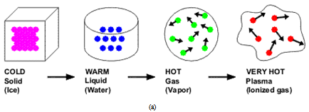 | Figure 1a. Plasma production by additional of thermal energy |
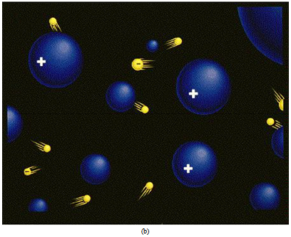 | Figure 1b. Ions and electrons make plasma |
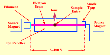 | Figure 2. The electron impact ion source types yields from electron impact ionization process |
3. Ionization Methods
- Collision processes of positive ions with atoms and molecules may be classified as elastic and inelastic[15]. In an elastic collision, there is no change in the internal energy of the collision partners. Inelastic collision processes include ionization, stripping, electron capture and excitation of atoms, ions and molecules, for which the internal energy of the collision partners has to be changed. This energy can be distributed among the collision partners or may be converted into internal energy of the products. After an inelastic collision, the internal energy may decrease (exothermic reaction), increase (endothermic reaction) or remain unchanged (resonant reaction).Ionization of neutral atoms to form the plasma state can be accomplished through a number of different processes as, surface ionization (thermal ionization)[6], photo ionization, field ionization[16] and laser ionization. Ion sources that do this kind of ionization are called surface ionization sources. Another ionization process, more widely used in the technology of plasma preparation is electron impact[17], where, in this process, ionization can be produced when an electron collide with a neutral atoms in a gas.
3.1. Electron Impact Ionization
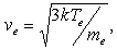
- It is the most fundamental kind of ionization mechanism in which the ionization of neutrals by collisions with electrons in a gas. In this case, the free electrons in the gas are accelerated by an applied electric field to energy sufficient to cause ionization when they collide with a neutral. In the collisions more free electrons are created and the discharge grows (Fig.2). For ionization to occur, a certain minimum energy is needed from the electron-neutral collision. The electron energy must exceed the energy needed to remove the outer most bound electron from the neutral atom, called the ionization potential (Ee > Vi), this is the first ionization potential. Actually, the probability of ionization increases with electron energy. In plasma, the mean electron energy is 3/2KTe, where Te is the plasma electron temperature. When the electron temperature is several times the ionization potential of the gas being ionized, electron impact ionization within plasma is maximum. Ex: Freeman ion sources, ECR ion sources, Magnetron ion sources.
3.2. Surface Ionization
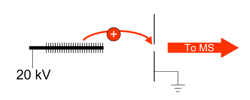
- It is defined as atoms can be ionized by contact with a hot metal surface. The residence time of particles on the surface is long enough for them to come into thermal equilibrium with the hot surface (Typically 10-5 to 10-3 S). The concept of surface ionization involves the ionization of a low ionization potential element (I) on a high work function surface (Ф) hot enough to desorb the ions thermally (Fig.3)[18]. Hot surface of a metal with high work function ionizes elements with low ionization potential (like alkalis)
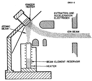 | Figure 3. The surface ion source types yields from surface ionization process[18] |
3.3. Field Ionization
- It is the process by which atoms or molecules adsorbed on or passing near to a surface, are ionized by a high electric field at the surface (Fig.4).
 | Figure 4. The field ionization process |
3.4. Ion Impact Ionization
- Ion-atom collisions that involve the transfer of an electron between the interacting particles are called charge-transfer or charge-exchange collisions. In the simplest case, an energetic ion collides with a low-energy neutral atom to produce a cold Ion and fast neutral. Charge exchange is rarely a useful ion production mechanism in ion sources, but is an important loss mechanism in hot plasmas. The ion energies required to cause ionization are high compared to electron impact ionization. This is because of the ion-electron mass ratio and the high ion energy required for the ion to have the same speed as a lower energy electron; the ionization cross-section maximizes when the fast particle has a speed equal to that of the orbital electron to be removed.
3.5. Photo Ionization
- When an intense beam of high energy photons is passed through a gas or vapor, can be ionized. The absorption of the photon by the atom will result in ejection of an electron .i.e., photo ionization, if the photon energy exceeds the ionization energy of the atom, hν > e and any excess photon energy is carried off as electron energy (Fig.5).
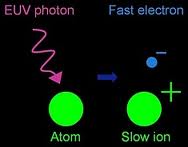 | Figure 5. Photo ionization |
4. Gas Discharge Techniques
- In the ion sources utilizing various types of gas discharge the ions are generated in the elementary physical processes taking place in the discharge. The discharge is self maintained, if the particles produced by the discharge processes compensate for the particle loss. To obtain a continuous ion current from the source, the gas discharge by which the ions are produced must also be continuous. It is valid, only if the electrons and ions lost in the process are supplanted by electrons and ions generated in the discharge or by the electrons from another source. The discharge is selfmaintained, if the particles produced by the discharge processes compensate for the particle loss. All the types of ion sources create a gas discharge in the form of plasma. There are two main types of the gas discharge:(1) D.C (Direct current) gas discharge; the discharge is self maintained by a D.C field applied between the anode and the cathode, which are immersed inside the discharge vessel. In self-maintained the discharges can be classified into three types according to the current which they carry, these are:(a) The Townsend discharge, which carries currents up to 10-6 A,(b) The glow discharge, which carries currents from 10-6 to 10 -1 A,(c) The arc discharge, which carries currents more than 10-1A.(2) A.C (Alternating current) gas discharge; The discharge is initiated inside an insulating discharge vessel by a high frequency field applied to the electrodes which are usually located externally outside the discharge vessel.A DC (Direct current) discharge can be achieved by applying a DC voltage between two conducting electrodes which are inserted into a gas at low pressures[11]. A schematic drawing of the plasma formation is given in Fig.6.
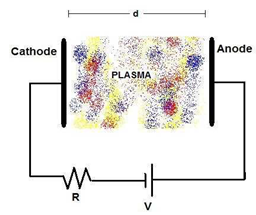 | Figure 6. Plasma formations by DC discharge[11] |
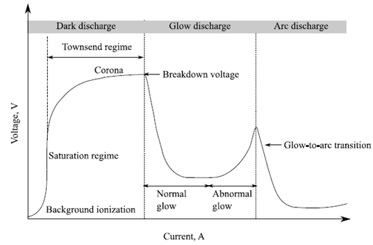 | Figure 7. The different discharge regions for a dc discharges[14] |
- Different types of discharges and plasmas can be obtained depending on the applied voltage and the discharge current (Fig.7)[14]. The Townsend discharge is a self-sustained discharge characterized by a low discharge current. The transition to a sub-normal glow discharge and to a normal glow discharge is marked by a decrease in the voltage and an increase in the current. An abnormal glow discharge develops as the current is increased even further. Finally, at very high currents, the discharge undergoes an irreversible transition down into an arc (glow-to-arc transition).
5. Extraction of Ions from Plasma
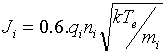
- The extraction process of ions from the generated plasma plays a crucial role while developing an ion source. Ions move randomly inside the plasma with free electrons. Each ion has different kinetic energy. The extraction systems for the different types of ion sources consisting the plasma electrode and the puller ground electrode are generally used during the last decades (Fig.8)[19]. The trajectories of the accelerated ions which determine the beam quality at the extraction region are affected by several factors as electric and magnetic field strengths, the shape of the emitting plasma surface and space charge density of the beam itself[3]. The boundary layer between the plasma and the extracted ion beam is called the plasma meniscus. The position, depth and curvature of this layer depend on the plasma density and temperature of the plasma (electrons and ions). Fig. 9 presents the plasma meniscus in three cases, (a) Convex, (b) Flat and (c) Concave plasma[20].
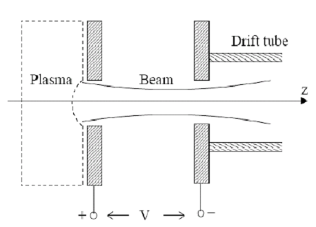 | Figure 8. Basic extraction system |
 | (1) |
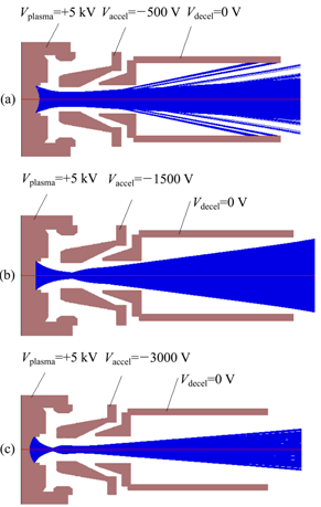 | Figure 9. The plasma meniscus for (a) convex, (b) flat plasma and (c) concave plasma[20] |
 | (2) |
 | (3) |
 | (4) |
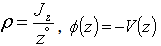
 .The electrostatic potential is determined from the space charge density ρ via Poisson equation with:
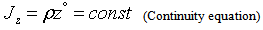
  The relation between the current density Jz and the ion velocity ν follows from the continuity equation
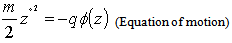
  Thus, there are three equations as:
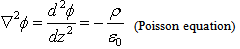 | (5) |
 | (6) |
 | (7) |
 and
and 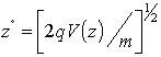 From eq.7 into eq.6 and eq.6 into eq.5, yields,
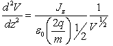 | (8) |
 then,
then,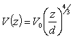 with the relation
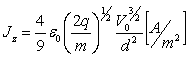 | (9) |
 | (10) |
5.1. Types of Plasma Sources
- Ion sources are devices for producing and delivering ion beams that may be directly used from the source or after acceleration by a simple or complex accelerator structure. Ion sources may be classified according to the ion characteristics in sources of positive ions and sources of negative ions. Ion sources can be classified in many different ways corresponding to a wide range of source and beam characteristics, parameters, and applications. One can categorize according to beam current intensity, ion beam charge state, or ion species, or according to whether the source is short pulse, long pulse, or dc, etc. Several types of plasma ion sources exist which are being used with a variety of accelerators or in research. The sources principally differ in the means of producing the discharge or the physical arrangement for extracting the ions from the plasma. Historically, the first major application of ion sources was used for injection into particle accelerators, initially for the relatively simple high voltage accelerators and later for the growing spectrum of linear and circular machines. To match the capabilities of the accelerators the ion source parameters require were in general quite modest, for example calling for beam current only is the micro ampere range. As the diversity and performance of particle accelerators expanded, so also have the ion source requirements grown, and sources used in this field today include Penning source for linear accelerators, cyclotrons and many others. The injection requirements of modern accelerators can be quite sever, calling for very stable and reliable ion beam often of high charge state and high current. The field of ion implantation has grown steadily as a mature industrial technology for semiconductor material fabrication today. Ion implantation is a surface modification technique with scientific and technological application wider than for semiconductor materials processing alone and there are active research communities in nonsemiconductor areas such as, for example, metallurgical, ceramic, polymer, superconductor electro-optics materials synthesis and modification. Applications such as ion beam lithography, micromachining and material surface characterization using ion beam call for low current, finely focused beams and field emission liquid-metal ion source are often used for this purpose. One of the important applications is the treatment of polymers using ion beams. Plasma ion sources may be divided according to the type of gas discharge used.
5.2. Glow Discharge Ion Sources
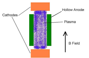
- The typical Penning ion source (PIG-arrangement) is shown in Fig.10, for production of singly and multiply charged ions ( MCI), the discharge is typically operated in homogeneous magnetic field of some kG, at gas pressures between 10-4 Torr and some 10-1 Torr.
 | Figure 10. PIG ion source |
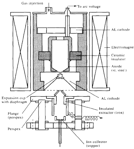 | Figure 11. Cold cathode Penning ion source[24] |
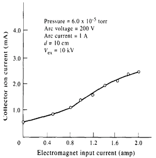 | Figure 12. influence of the magnetic field on the collector ion current24] |
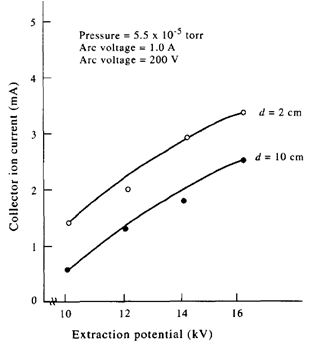 | Figure 13. Influence of the extraction potential On collector ion current at distance d = 2, 10 cm[24] |
5.3. Arc Discharge Ion Sources
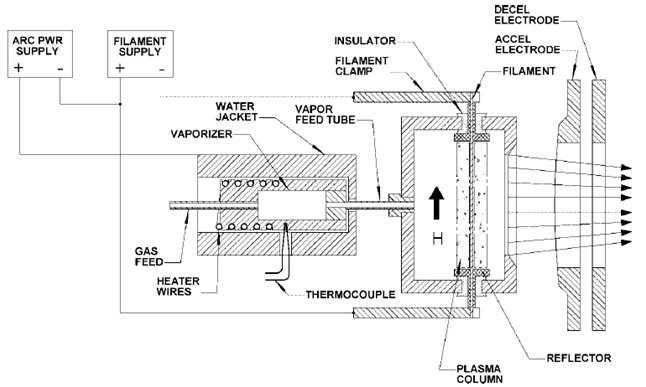
- An example of a high current arc discharge ion source system is the Freeman type ion source[26] which is capable of ionizing the majority of elements of the periodic table gases, liquids and solid materials. The heavy ion beam injector T-5010 with a Freeman type ion source, used at our laboratory for different applications, is supplied by the Efremov Research Institute of Electro physical Apparatus, Saint Petersburg, Russia. The Freeman ion source and its associated electrical circuit shown in Fig. 17 represent an example of arc discharge, where the arc current between the anode and the cathode is 1 A to 6 A and the arc voltage is just 35 V to 70 V. It consists of a thermo-emission tungsten filament (cathode) surrounded by a cylindrical anode made of molybdenum. A cathode rod, usually 2 mm in diameter and made of tantalum or tungsten, is heated with a current varying from 120 A to 180 A. The discharge is formed between the thermo-emission tungsten filament as cathode, and cylindrical anode surrounding it. The applied external permanent magnetic field of about 100 Gauss in the discharge gap is used to help in the generation of stable plasma and to increase the ionization efficiency.The working substances are admitted into the discharge region through three holes in the anode A of the source. The working gases are supplied through one hole in the side wall of the anode. Vapors of the working liquids are supplied through another hole from the external container. Solid substances having a medium or high vaporization temperature are supplied from an internal oven through a hole in the back wall of the arc chamber (anode). The oven is made from molybdenum material. The oven temperature is monitored by means of a thermocouple.The ion beam current is extracted from the discharge through an emission slit 40 mm in length and 0.5 mm to 2 mm in width. The extracted ions of various elements are accelerated in a four electrode acceleration/deceleration system to obtain energy of up to 40 keV to 50 keV. The four electrode acceleration/deceleration system has two ion accelerating gaps and one ion decelerating gap which allows the ion beam to keep a constant value of beam energy at the ion source outlet. The two accelerating gaps increase the ion acceleration, while the decelerating gap reduces the ion beam divergence angle at the ion source outlet. The ion source and the accelerating system are water cooled.Fig. 18 shows the relation between the output ion beam current and the acceleration voltage at a constant pressure, cathode current, extraction voltage and discharge current, using argon and krypton gases. It is obvious that the output ion beam current reaches 11 mA at an accelerating voltage of 45 kV in the case of argon gas while it reaches 4.2 mA in the case of krypton gas[27].The Freeman ion source is one of the most appropriate for use in ion implanters[26] and isotope separation till now. The Freeman ion source is capable of delivering stable and high ion beams current for a variety of elements, gases, liquids and solids. The excellent performance of the Freeman ion source has made it the most successful source for ion implantation, ion beam surface modification of materials, isotope separation and industrial applications, especially for semiconductor purposes. Many companies delivering ion implantation machines supply them with Freeman ion sources. Also Freeman ion source can be used for research in physics and technology of ion beam generation and extraction and transport system. An analysis has been made for an implanted krypton ion beam in a zinc specimen using laser ablation inductively coupled plasma mass spectrometry with the aiding a Freeman type ion source[28]. Photographs show the examined zinc specimens are presented. The depth profile shows that the highest concentration of krypton ions under the surface of the zinc specimen is located at about 10 m. The movable Faraday cup is designed for measuring a total beam current at the source outlet, for shutoff a beam to control the exposure time. The Faraday cup is mounted in the vacuum chamber. The zinc specimen was placed at a distance of 1cm from the Faraday cup. This specimen has a thickness of 1.5 mm and has been exposed to the krypton ion beam for a period of 3 hours. The operating parameters for the ion source are kept as follows: Vacc = 40KV, Vex= 17KV, Iex= 0.6mA, Ib= 7.2mA, Id =1A, Vd = 61V and at a pressure of 3x10⁻⁵ Torr.
 | Figure 14. Low energy accelerator with electrical circuit[25] |
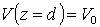
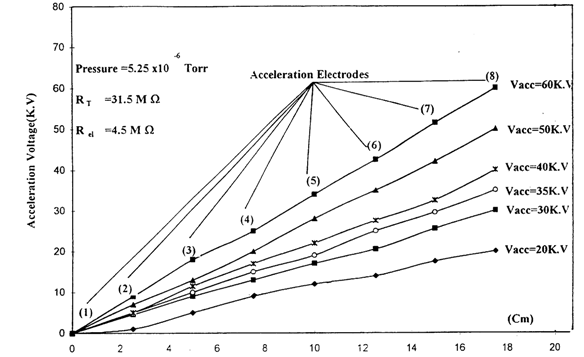 | Figure 15. Potential distribution along the acceleration electrodes[25] |
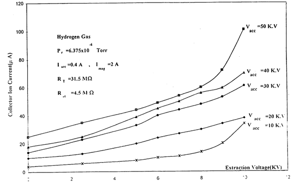 | Figure 16. Influence of extraction voltage on collector ion current at different accelerating voltages[25] |
 | Figure 17. Freeman ion source as high current ion implanter[26] |
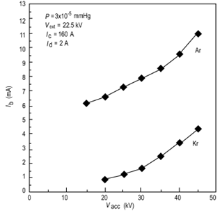 | Figure 18. Output ion beam current versus accelerating voltage using argon and krypton gases27] |
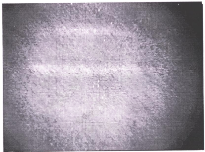 | Figure 19a. Zinc specimen before exposure to the krypton ion beam |
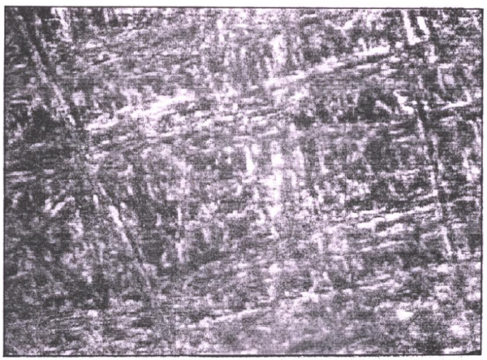 | Figure 19b. Zinc specimen after exposure to the krypton ion beam |
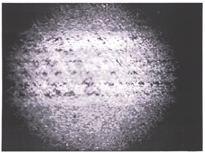 | Figure 19c. Zinc specimen after exposure to the krypton ion beam by laser ablation |
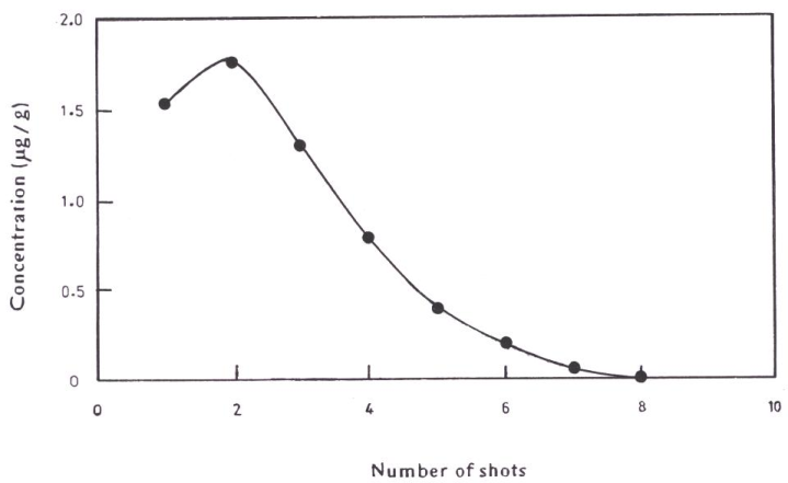 | Figure 20. Depth distribution of krypton ion beam on the surface of zinc specimen after implantation by Kr ion beam |
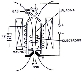
 | Figure 21. Main elements of duoplasmatron ion source |
5.4. High-frequency Ion Sources
- In (high) radio-frequency sources[27], the absorbed rf-energy feeds a self-sustaining discharge, provided that the discharge vessel is made from an insulating material (Pyrex, quartz or alumina), no electrodes must be in contact with the plasma. In practice, an RF discharge is formed in a vacuum vessel filled with a gas at a pressure of about 10-3 to 10-2 torr. A few hundred watts of RF power is required to establish a suitable discharge. There are two ways in which a low pressure gas can be excited by RF voltages; (1) a discharge between two parallel plates across which is applied an alternating potential (capacitive coupled discharge) and (2) a discharge generated by an induction coil (inductively coupled discharge). Most RF ion sources are operated with the second type of discharge. In this case, electrons present in the vacuum vessel filled with a gas are excited into oscillation by RF electric field. They quickly acquire enough kinetic energy to form plasma by ionizing the gas particles. Fig.22 shows a schematic diagram of a Thonemann type inductively coupled RF ion source. It is consists of a quartz discharge chamber surrounded by the RF- induction coil from the outside. There are four external variables that affect the character of the discharge and the resulting ion beam; the gas pressure in the discharge chamber, the RF field (its magnitude and coupling to the plasma), the external magnetic field and the extraction voltage.The radio frequency (RF) ion sources have many advantages; its clean resulting from absence of metallic surfaces in the discharge, high proton percentages (up to 90%), operation at low pressure yields a higher efficiency with respect to gas consumption and simplicity of construction and maintenance. The radio frequency (RF) ion sources can be used in research applications such as cyclotrons, synchrotrons, neutral beam injectors for fusion research and production of multiply charged ions. Also it can be used in industrial applications such as ion implantation system, ion beam etching, ion beam doping, ion beam lithography, material surface modification and proton therapy machines.Radio frequency ion sources are widely used in direct voltage accelerators owing to their long life and good beam characteristics.
 | Figure 22. Thonemann type RF ion source27] |
6. Conclusions
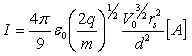
- In this paper, the generation and maintenance of plasma is one of the main challenges in plasma technology. Plasma production usually involves some type of gas discharge. At low currents, a non-self sustaining Townsend discharge occurs. Breakdown occurs when ionization and secondary electron emission become large enough to make the discharge self-sustaining. As current increases, a glow discharge becomes an arc when cathode heating makes thermionic emission significant. The currents which can flow between cathode and anode is limited by space charge effects to a value
 . The choice of the plasma source and its particular design depend on the specific requirements of each application. In this paper, we discussed only a small selection of plasma sources that designed, constructed and optimized locally for use in research and in low energy accelerators. Furthermore, the state of maturity of the various plasma sources discussed in this paper is quite different from source to source. Many opportunities remain for further research and development of plasma sources in order to meet the demands of the various diverse plasma technological applications.