M. Surdu1, A. Lameko2, A. Labuzov3
1Institute of electrodinamics, Kiev, 04080, Ukraine
2Ukrmetrteststandard, Kiev, 04080, Ukraine
3Promix LTD. Kiev, 04080, Ukraine
Correspondence to: M. Surdu, Institute of electrodinamics, Kiev, 04080, Ukraine.
| Email: |  |
Copyright © 2012 Scientific & Academic Publishing. All Rights Reserved.
Abstract
To measure the impedance parameters in the wide dynamic range we need always the great number of the standards. The precise standards, used for the accurate measurements are very expensive, have great sizes and weight. In addition, to change the inner standard value we have to use complicate and expensive switchers. Therefore, the appropriate devices have great cost and dimensions. In this report we describe the new approach, which permits to reduce twice the number of standards and switcher, used for the widening of the measurement range. This approach is based on the measurement of the reciprocal impedance parameters on the two adjoining subranges of measurement.
Keywords:
Wide Range, Impedance Measurement, Standards, Number
1. Introduction
Every process of the measurement of the impedance parameters consists in the comparison of the parameters of the standard with the parameters of the object to be measured by means of the comparator. Last one determines the ratio  of the compared parameters. Usually the comparator determines this ratio in the range
 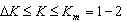 where:
  is comparator’s sensitivity and
  is the maximal value of the
 . Uncertainty of measurement, caused by the comparator, therefore, will be:
  . This value changes from 100% (when K=∆K) to minimal relative value (when K = Km). Of course, the uncertainty, achieving 100%, doesn’t satisfy anyone. Because of this, we change the subrange of measurement, when the uncertainty of measurement exceeds permissible value, or then the measured impedance exceeds value of the impedance of the standard. Today the unique means to change the subrange consists in the changing of the standard value.
2. Description of the Problem
Suppose that we permit the increasing of the uncertainty in the range of measurement on L ratio. Let the ratio of the impedance values, to be measured with permitted value of the uncertainty, is M. In this case we have to divide all therange of measurement on N= M/L subranges. To cover N subranges we need N standards at least. Such approach is commonly used[1,2].The price of the accurate standards is very high. All these standards, having wide range of impedance, are switched by complicate switchers. These obstacles increase the complexity of the devices, increase their price, dimensions and weight. What’s why it is so significant to decrease the number of the standards, used for the widening of the range of the measurement.
3. Decision of the Problem
To explain our proposal[3] let us consider, for example, the measurement of impedance in the range, with M=8 ( ). Let (it is mostly made) us admit that uncertainty, caused by comparator, increase on 10 times on the subrange (decimal subranges with L=10). It means that we have to divide all the range of measurement on 8 subranges. Usual approach led to using of 8 standards.
 | Figure 1. Dependence of the K and  on the measured value for the well known approach on the measured value for the well known approach |
The dependence of the coefficient K on measured impedance is the straight line, having disruptions on the bounds of the subranges.The dependence of the uncertainty δk on measured impedance is the hyperbola, having disruptions on the bounds of the subranges.These dependencies for four subranges are shown on Fig. 1.Let us divide all these 8 subranges in 4 pairs of adjoining subranges.Let us consider one of these pairs.On the first subrange of this pair we measure the impedance Zx, using standard Z0 and comparator which has: | (1) |
The next formula describes the measurement process | (2) |
In this case the range the measurement of Zx lies between: | (3) |
Suppose that on the second subrange of this pair we measure admittance Yx, using standard Y0 and the same comparator, which has:  .In this case the range of the measurement of Yx lies between:
 | (4) |
Let we’ll demand that standards on first and second subranges will have the same value: i.e.: | (5) |
It permits us to use one standard only for both adjoining subranges.There are no problems today to calculate the impedance by measured admittance or vice versa. It means that using the same standard we can measure the impedance Zx in the range from to
to  or admittance in the range from
 to
to  . The range with permitted uncertainty in case of decimal subranges lie between
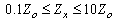 , i.e. on this pair of subranges, the ratio of the impedance measurement increases to 100 using one standard only.
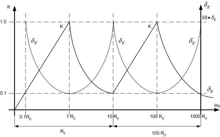 | Figure 2. Dependence of the K and  on the measured value for the new approach on the measured value for the new approach |
The dependence of the K and  on the measured value Zx for four subranges is shown on fig. 2. It has an unusual appearance.The dependence of the coefficient K on measured impedance in this case is the straight line on the odd subranges and hiperbola – on the even subranges. The dependence of the uncertainty δk on measured impedance is the decreasing hyperbola on the odd subranges and the increasing hyperbola on the even subranges.In such way we can cover all the range of measurement with resistance ratio 108, using 4 pair of subranges with one standard only on every pair and decrease, in comparison with traditional way, the number of standards from 8 to 4 only. To perform the measurement of admittance Yx usually the mode of constant voltage on the Yx is maintained on the whole range of measurement.To perform measurement of the impedance Zx usually the mode of constant current on the Rx is maintained on the whole range of measurement.It permits us to say that to pass from one adjoining subrange to another, we simply have to pass from first to second mode of measurement, maintaining constant current or constant voltage on the object to be measured.Described approach can be used in the different measuring circuits. On the Fig.3 there is shown the classic transformer bridge with current comparison[4,5].
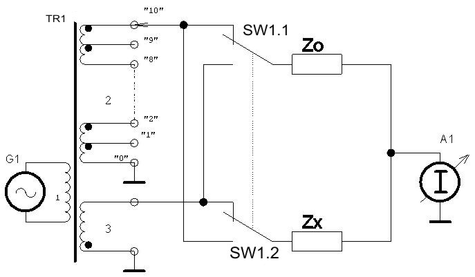 | Figure 3. Transformer bridge |
The bridge consists of the transformer TR1 with two secondary (2 and 3) and one primary (1) winding, being connected to the generator G1, the balance indicator A1, and the switcherSW1. The standards to be compared Zo and Zx, are connected through switcher SW1 to secondary windings. Bridge is balanced by changing of the secondary winding (2) turns. Let the switcher SW1 is in the initial position. In this case the balance equation is as follows: | (6) |
If  admittance is measured in the range0xo (or impedance Zx is measured in the range Zo < Zx < ∞).Let us transfer the switch SW1 in the opposite position. In this case the balance equation is the next:
 | (7) |
The range of impedance measurement is 0 < Zx < Z0. So, whole range of resistance measurement is 0 x < ∞. If we permit increasing of the uncertainty in 10 times, the range of impedance measurement is: 0.1 Zo < Zx < 10 Z0. As an example, the possible subranges of measurement using four impedance standards are given in the table below.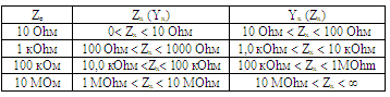 Described approach can be used in every wide range measuring circuit. Let us consider the measuring circuit of the impedance meter, using the protecting amplifier (such kind of the measurement circuit is widely used by many industrial producers[6-10.] in their serial developments). The simplified diagram of such circuit is shown on Fig.4.
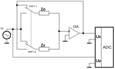 | Figure 4. Impedance meter circuit |
The measuring circuit contains the generator G1 and the vector analog-to-digital converter ADC. The output of the generator G1 is connected directly to the reference input of the ADC and, through switcher SW1, to the standards Zo or Zx to be compared. Other leads of these standards are connected to the input of the protecting amplifier OA. The output of this amplifier is connected directly to the measuring input of the DAC and to other input of the switcher SW1.In initial position of the switcher SW1 the measuring circuit measure admittance by the equation: | (8) |
Then the switcher SW1 is switched in the opposite position the measuring circuit measure the impedance by the equation: | (9) |
Let us measure the impedance on eight subranges. Using described approach it is possible to measure impedance in the whole range of measurement using four standards only. The table below shows these subranges.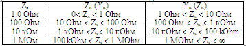 It is necessary to underline the fact, that this non traditional approach, needs the development of the appropriate non traditional algorithms of automatic range choice.During the choice of the subrange we have to choice appropriate standard Zo. To choice this standard the magnitude of the signal Ux on the output of the amplifier O is analyzed. It must not to decrease dynamic range Ud of the amplifier OA and not to be below the 0.1Ud. To get the stabile measurement of the impedance on the bound between two adjoining subranges usually the next inequalities are set:0.09Um ≤ Ux ≤ 1.1Um, where: Um ≤ 0.9Ud.These inequalities permit to create the hysteresis on the bounds of the subranges and to get stable measurements in automatic mode. Of course, during the subrange changing we have to change the mode of supply (current generator or voltage generatorTo ensure appropriate measurements using proposed algorithm, the analysis of the voltage, acting on the impedance to be measured or the current which flow through this impedance (depends on the subrange of the adjoined pair) has to be provided. Results of this analysis are used to set the appropriate voltage on measured impedance or appropriate current through this impedance independent on the value of the measured impedance by control of the generator voltage (software current or voltage generator, not hardware one). In such way we don’t need to create special current or voltage generators to supply the impedance to be measured.
4. Application
Proposed method of the range of measurement widening has been used in the universal automatic precise impedance meter MNS-1100,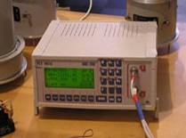 | Figure 5. Impedance meter MNS-1100 appearance |
Bridge has 10 decimal subranges of measurement and use 5 standards only to cover all the range of measurement (appearance see on Fig5). It has weight only and measure all impedance parameters (inductance, capacitance, resistance, dissipation factor, etc.) in wide dynamic (10-5 Ohm ≤ |Z| ≤1011Ohm) and frequency (from 0.5 Hz to 1 MHz and DC) range with the discreteness of frequency setting less than 0.002%. Main uncertainty of measurements doesn’t decrease 0.01% for any parameters.MNS-1100 has been certified in Ukraine, Russian Federation, Byalorussia, Kazakhstan.In some cases using of decimal subranges isn’t best decision. Let we’ll consider development of the devise for temperature measurements using platinum thermometers which could satisfy temperature scale ITS-90. Let we will use comparator with sensitivity  ppm and nonlinearity
  in whole range
  better than 0.5 ppm (such comparator can be created, for example, using modern ∑-Δ ADC). Most accurate platinum thermometers for IRS-90 have resistance, which lie in the range from 10 Ohm to 300 Ohm. For high temperature measurements the thermometers with resistance up to 1 Ohm are used, but relative uncertainty of measurement of these thermometers is much higher. The same situation occurs for low temperatures where the thermometers with higher resistance (up to hundreds of Ohm or kOhms) could be used. Analysis shows that for such measurements optimal decision consists in using of two inner standards with resistances 25 Ohm and 100 Ohm and measurements on four ranges using proposed approach. Whole range of measurement in such way is divided onto four subranges: 0-25 Ohm, 25-50 Ohm, 50-100 Ohm and 100-∞Ohms. In this case on the range of measurement from 10 Ohm to 250 Ohms, where we need highest accuracy of the measurements coefficient K will change in the range
  only. It permits to decrease nonlinearity
  of measurements in this range to 0.1-0.2 ppm (temperature uncertainty less than on 0.05 mK) and restrict change of relative sensitivity to values 0.1ppm
 0.05 ppm (temperature sensitivity better than 0.02-0.01 mK). On the ranges 1-10 Ohms and 250-2500 Ohm the sensitivity of measurements will decrease up to 1 ppm (0.2 mK) and uncertainty could achieve 0.5-1.0 ppm (1 mK). It is enough for most cases of temperature measurements.
5. Conclusions
The method of reducing of the number of standards, used to widen the range of measurement in impedance meters has been proposed. This method permits to reduce twice the number of standard and sufficiently decrease the devise cost and weight.In conclusion, we would say that proposed method of the number of the standard minimization could be used for measurement of another values (weight, voltage, etc.). But in this case we have to use unusual reciprocal parameter (i.e. 1/kg, 1/V etc.).
References
| [1] | Орнатский П.П. Автоматические измерения и приборы (аналоговые и цифровые). – Киев: Вища школа, 1980. – 560 с. |
| [2] | Новик А. И. Системы автоматического уравновешивания цифровых экстремальных мостов переменного тока / - Киев: Наук. Думка, 1983. – 224 с. |
| [3] | The patent 90787. Inventors: M. Surdu, A. Lameko, A. Labuzov. Способ многодиапазонного измерения параметров импеданса. – Publ. 25.05.2010 Bul. №10. |
| [4] | Трансформаторные измерительные мосты / Под ред. К.Б.Карандеева. – М.: Энергия, 1970. – С.219-263. |
| [5] | Kibble B.P., Rayner G.H. Coaxial AC bridges / Bristol, Adam Hilger Ltd. 1984. |
| [6] | H. P. Hall "Method of and Apparatus for Automatic Measurememts of Impedance or Other Parameters with Microprocessor Calculation Techniques", US Patent 4,196,475, April 1, 1980, filed Sept 2, 1976 |
| [7] | GenRad, Digibridge /1693- RLC Meter, operation manual. |
| [8] | s, series 7400, 7600, operation manual. |
| [9] | Tegam, Programmable Impedance / LCR Meter, 42.0 Hz-5.00 MHz,, operation manual.. |
| [10] | Agilent, Precision LCR Meter E4980A, 20 Hz to 2 MHz , operation manual. |
 Abstract
 Reference
 Full-Text PDF
 Full-Text HTML