Chau-Chin Chang
Department of Mechanical Engineering, Southern Taiwan University of Science and Technology, Tainan, Taiwan
Correspondence to: Chau-Chin Chang, Department of Mechanical Engineering, Southern Taiwan University of Science and Technology, Tainan, Taiwan.
| Email: |  |
Copyright © 2024 The Author(s). Published by Scientific & Academic Publishing.
This work is licensed under the Creative Commons Attribution International License (CC BY).
http://creativecommons.org/licenses/by/4.0/

Abstract
This paper presents a new method to estimate the moving directions of two motorcycles before a collision by looking at their ground scratch marks. Using the principle of impulse and momentum, the relationship between pre-impact velocity, impact velocity change, and post-impact velocity of each motorcycle in collision is derived. These three velocities form an impact velocity triangle, abbreviated as “velocity triangle” for each motorcycle. By assuming two motorcycles’ moving directions before the collision as an impact situation together with the lengths and directions of ground scratch marks caused by the sliding of the motorcycles on the ground, one can draw two velocity triangles and decide whether the assumed impact situation is reasonable or not. Three accident diagrams in Taiwan are used as examples to illustrate the application procedure in detail. When two motorcycles move in the same direction with small difference in mass, then the straight-moving motorcycle has more oblique ground scratch mark than that of the one deviating to or turning left or right after a sideswipe collision. The method presented in this paper can help relevant personnel estimate the moving directions of the two motorcycles before the crash in traffic accident reconstruction without knowing the details of dynamics theories.
Keywords:
Ground scratch marks, Principle of impulse and momentum, Velocity triangle, Moving directions before collision, Sideswipe collision
Cite this paper: Chau-Chin Chang, Motorcycles Paths Estimation in Traffic Accident Reconstruction – Ground Scratch Marks Method, International Journal of Traffic and Transportation Engineering, Vol. 14 No. 2, 2024, pp. 31-40. doi: 10.5923/j.ijtte.20241302.02.
1. Introduction
In Taiwan and Southeast Asia, many lightweight street motorcycles and scooters are driven in crowded streets. Collisions often occur between motorcycles. One common type of collision happens when two motorcycles move in the same direction and one of them swerves left or right. The motorcyclist in the back often insists that the rider in the front veered over unexpectedly, while the rider in the front would say the motorcyclist in the back should have maintained a safe riding distance. In this situation, since both motorcycles have the same right of way, if the possible moving directions of the two motorcycles before the collision can be estimated from the ground scratch marks caused by the motorcycles sliding on the ground, it has great reference value for the distinction of responsibility for the accident.In developed countries, the number of accidents between two motorcycles is relatively small comparing to that of collisions between motorcycle and car. The research on motorcycle accident reconstruction mainly focuses on how to determine the impact speeds of these two types of vehicles. Wood, et al., [1] applied permanent deformation method to estimate motorcycle-to-car and scooter-to-car impact speeds. McNally and Bartlett [2] used conservation of linear and rotational momentum to calculate the impact speeds of motorcycle and car. Obenski and Hill [3] discussed the methods used in motorcycle speed reconstruction. Rose [4] applied wheelbase reduction and momentum methods to study motorcycle collision with car. Masory, et al., [5] applied five different methods to estimate the impact speeds of motorcycle and car. However, these papers and books don’t have motorcycle-to-motorcycle collision cases or examples. Chang [6] used gyroscopic moment and roll moment to study the falling direction of a motorcycle after collided with another motorcycle or car.By using two motorcycles’ ground scratch marks after a collision, this paper proposes a new method to estimate the moving directions of two motorcycles before the collision occurs, which is important in traffic accident reconstruction. To simplify analysis, the rotational motion of the motorcycle’s body and rider can be neglected, since they are usually small before and after a collision. Hence, the motorcycle-rider system can be regarded as a point mass. Applying the principle of impulse and momentum [7], the relationship between pre-impact velocity, impact velocity change and post-impact velocity is derived. These three velocities form an impact velocity triangle, abbreviated as “velocity triangle”, for each motorcycle. The direction of post-impact velocity is the same as that of the ground scratch mark of the falling motorcycle after collision, while its magnitude is proportional to the square root of the length of the ground scratch mark. Using a force diagram, the magnitude and direction of the impact velocity change in a collision between two motorcycles are analyzed in detail. The direction of pre-impact velocity is the moving direction of the motorcycle before collision. Hence, after drawing the velocity triangles of two motorcycles, the moving directions of the two motorcycles before the collision can be estimated. The estimation can be even more accurate if supplemented by the directions of the two motorcycles falling to the ground [6]. The steps to draw velocity triangles with real accident diagrams in Taiwan are illustrated. The proposed method can be applied to collisions between two motorcycles from any directions. However, for the sideswipe collision of two motorcycles moving in the same direction, an important and simple conclusion is obtained. Several accident diagrams in Taiwan are used to validate the simple conclusion, which allows the appraisal personnel to quickly estimate which motorcyclist is at fault.This paper is divided into four sections with the first section providing the basic theory of motorcycle collision and velocity triangle analysis. In the second section, three accident diagrams in Taiwan are used as examples to explain the procedure to estimate the moving directions of two motorcycles before collision. Sideswipe accident between two motorcycles moving in the same direction is analyzed in the third section. The conclusion forms the last section.
2. Basic Theory and Velocity Triangle
2.1. Basic Assumptions
The basic assumptions in this paper for collision analysis are:1. Due to the short time of collision, forces such as gravity force and the reaction force of the ground to the motorcycle are small compared to the impact force, so they can be neglected.2. Since the purpose of this article is not to calculate the impact speed, one can assume that the motorcycle as well as its rider have the same velocity after the collision, and the rider position doesn’t need to be drawn in the accident diagram.3. Neglecting the deformation, the motorcycle is treated as a rigid body. Because the rotational motions of the motorcycle’s body and its rider before and after collision are usually small, they can be ignored. The motorcycle-rider system can be regarded as a point mass.
2.2. Impact Velocity Triangle
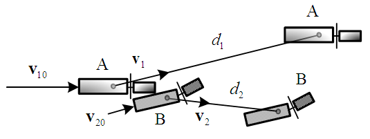 | Figure 1. Collision diagram of motorcycles A and B |
Figure 1 is a collision diagram of a straight-moving motorcycle-rider system A which is abbreviated as “motorcycle A”, colliding with a left-deviating motorcycle-rider system B, abbreviated as “motorcycle B”. The so-called “straight-moving” here indicates that the motorcycle runs in the direction of the lane, and the so-called “left-deviating” means that the motorcycle deviates from going straight to relatively the left. Since the motorcycle-rider system is regarded as a point mass and by using the principle of impulse and momentum [7], the impulse  generated by the collision that causes the momentum change
  can be written as
 | (1) |
where  is the result impact force of the collision. Using Equation (1), the impact velocity change
  of motorcycle A can be expressed as
 | (2) |
Where  is the system mass of motorcycle A,
  is the pre-impact velocity of motorcycle A and its direction is the same as that of motorcycle A moving before the collision. The
  is the post-impact velocity of motorcycle A and its direction is the sliding direction of motorcycle A after the collision which leaves scratch mark with length
  on the ground. Equation (2) can be rewritten as
 | (3) |
Similar equation for motorcycle B can be expressed as | (4) |
where  is the pre-impact velocity of motorcycle B and its direction is the same as motorcycle B’s moving direction before the collision,
  is the post-impact velocity of motorcycle B and its direction is the moving direction of motorcycle B after the collision which leaves ground scratch mark of length
  , and
, and  is the impact velocity change of motorcycle B.The
 and
and  constitute the impact velocity triangle of motorcycle A, while the
 and
and  form the impact velocity triangle of motorcycle B as shown in Figure 2. In this paper, impact velocity triangle is abbreviated as “velocity triangle”. The steps to draw the velocity triangles will be explained in Section 2.5.
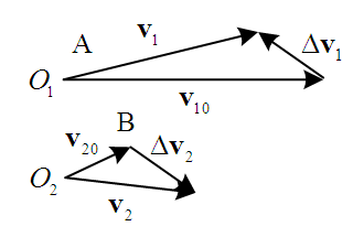 | Figure 2. The impact velocity triangles of motorcycles A and B |
2.3. The Relationship Between the Impact Velocity Changes of Two Motorcycles
Since the impact force in Figure 1 is an internal force for the whole system, the momentum is conservative. That is | (5) |
where  is the system mass of motorcycle B. Substituting Equations (3) and (4) into Equation (5), the relationship between the two impact velocity changes can be written as
 | (6) |
The negative sign in Equation (6) means that the direction of the impact velocity change of motorcycle A is opposite to the direction of the impact velocity change of motorcycle B.Equation (6) shows that the smaller the mass, the larger the impact velocity change. If two motorcycles with small difference in mass and assuming the riders have about the same weights, Equation (6) can be written as  . The majority of motorcycles in Taiwan are scooters and lightweight street motorcycles. Their mass differences are small. Hence, when drawing the impact velocity changes in the velocity triangles, they can be drawn as equal in length but opposite in direction.
2.4. Direction of Impact Velocity Change
When a motorcycle collides with another motorcycle or car, an equivalent normal impact force  perpendicular to the collision surface and an equivalent tangential impact force
  along the collision surface are generated at the collision area, and their resultant impact force and impulse are F and I, respectively. The impact velocity change is caused by the resultant impulse I, hence its direction is the same as that of the resultant impact force F. Using a straight-moving motorcycle A collides with motorcycle B that deviates from straight to the left shown in Figure 3 as an example. Assume that motorcycle A moves faster than motorcycle B. The impact force diagrams (abbreviated as “force diagrams”) of motorcycles A and B are shown in Figure 4. In Figure 4(a), the front right corner of motorcycle A collides with the left side of motorcycle B. The equivalent normal impact force
  is perpendicular to the left side of motorcycle B. The contact area of motorcycle A slides to the upper-right direction along the left side of motorcycle B, hence the equivalent tangential impact force
  goes along the left side of motorcycle B pointing to the upper-right direction. Applying Newton’s third law of motion, there are
  and
and  with opposite directions acting on motorcycle A, and their resultant impact forces F are shown in Figures 4(b) and 4(c).
 | Figure 3. Illustration diagram the straight-going motorcycle A collides with the left-deviating motorcycle B |
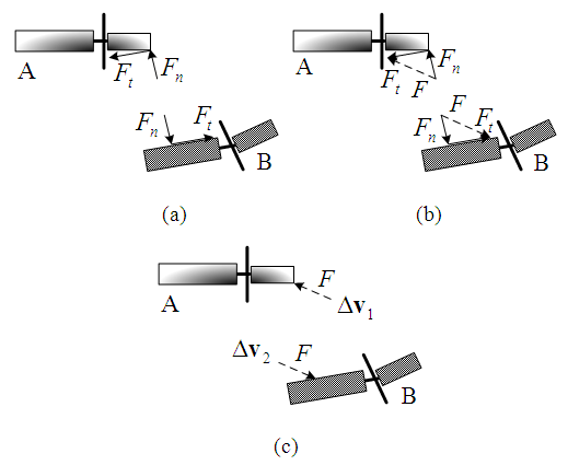 | Figure 4. Force analysis of the straight-going motorcycle A moving faster than the left-deviating motorcycle B |
Similarly, if the left-deviating motorcycle B moves faster than the straight-moving motorcycle A in Figure 3, the force diagrams are shown in Figure 5.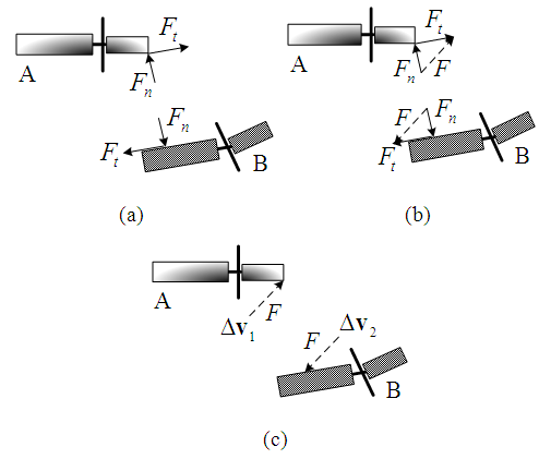 | Figure 5. Force analysis of the left-deviating motorcycle B moving faster than the straight-moving motorcycle A |
From Figures 4(c) and 5(c), a simple conclusion regarding the direction of the impact velocity change can be obtained. That is if the straight-moving motorcycle A is moving faster than the left-deviating motorcycle B, the direction of the resultant impact force F (i.e., the direction of the impact velocity change  ) is along the oblique front direction of the collision place of motorcycle B as shown in Figure 4(c). If the left-deviating motorcycle B is traveling faster when it hits the straight-moving motorcycle A, the direction of the impact velocity change
  of motorcycle B goes along the diagonal rear direction of the collision place of motorcycle B as shown in Figure 5(c).
2.5. Steps to Draw Two Velocity Triangles
Using the collision diagram of the straight-moving motorcycle A colliding with the left-deviating motorcycle B of Figure 1 as an example, the steps to draw the two velocity triangles are usually as follows:1. Draw an illustration diagram of the collision as shown in Figure 3.2. Take two points  and
and  as reference points. According to the lengths and directions of the ground scratch marks of motorcycles A and B, draw two vectors from points
  and
and  to represent the post-impact velocities
  and
and  of motorcycles A and B, respectively as shown in Figure 2.3. Draw the motorcycle that moves straight first. Since motorcycle A goes straight to the right, draw a vector from point
  to the right with adjustable length to represent the pre-impact velocity
  . Using the analysis in Section 2.4, motorcycle A hits the left side of motorcycle B at a faster speed, then the direction of the impact velocity change of motorcycle A is towards the upper left (see Figure 4(c)). Hence, draw a vector from the tip of
  with the upper-left direction to the tip of
  to represent
  . The velocity triangle of motorcycle A is completed as shown in Figure 2.4. For motorcycle B, the impact velocity change
  can be accurately obtained by applying Equation (6). If the mass difference of two motorcycles is small, then
  , and
, and  can be applied. Hence, draw from the tip of
  with
with  . Then connect
  to the starting point of
  to represent the pre-impact velocity
  and the velocity triangle of motorcycle B is completed as shown in Figure 2.
2.6. Procedure to Estimate the Moving Directions of Two Motorcycles Before Collision
The procedure is as follows:1. Confirm the corresponding collision areas of the two motorcycles.2. List the possible impact situations of the two motorcycles’ moving directions before the collision. Then, draw the illustration diagram for each situation.3. Draw the velocity triangles for each impact situation and analyze whether the situation is reasonable or not.4. Using the falling directions of the motorcycles after the collision can further confirm the correctness of the pre-impact directions.
2.7. Falling Direction of Motorcycle
To analyze the falling direction of a motorcycle after a collision, a motorcycle is divided into two groups, namely, the front assembly and the rear assembly. The components that rotate together with the handlebar constitute the front assembly, which include the front wheel, front wheel cover, front fork, handlebar, and rearview mirror, etc. All the other components that do not rotate together with the handlebar belong to the rear assembly, including the frame, engine, fuel tank, seat, transmission system, rear suspension system, exhaust pipe, and rear wheel, etc. [6]. An illustration diagram of the front and rear assemblies of a motorcycle is shown in Figure 6 [6].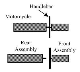 | Figure 6. Illustration diagram of the front and rear assemblies of a motorcycle [6] |
The utilization of extensive knowledge and understanding in dynamics theories are not necessary to determine the falling direction of a motorcycle after a collision. One can quickly make a judgment by knowing the turning direction of the handlebar for collision of the front assembly and impact force direction in rear assembly. Chang [6] summarized how to determine the falling direction of a motorcycle after collision as shown in Table 1.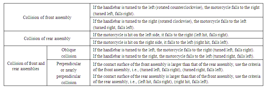 | Table 1. Simple Judgment Table for the Falling Direction of a Motorcycle After Collision [6] |
3. Examples
Three accident diagrams from appraisal cases [8] in Taiwan are used as examples to illustrate the procedure to estimate the moving directions of two motorcycles before collision.Example 1: the accident diagram of the collision of two motorcycles is shown in Figure 7.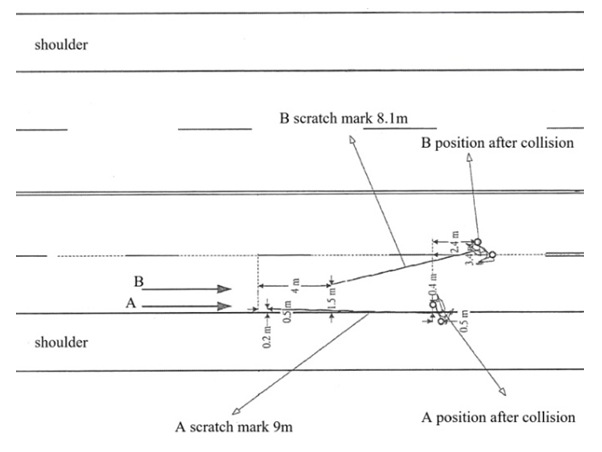 | Figure 7. Accident diagram between two motorcycles [8] |
According to the photos and information provided by the police, the front end of motorcycle B collided with the left side of motorcycle B. There are three possible impact situations. Situation (a): straight-moving motorcycle B moves faster and collides with left-deviating motorcycle A.The illustration diagram is shown in Figure 8(a). Based on the lengths and directions of the ground scratch marks of motorcycles A and B, draw two vectors from reference points  and
and  to represent the post-impact velocities
  and
and  , respectively. Since motorcycle B goes straight from left to right, draw a horizontal vector from point
  to the right with its length adjustable to represent the pre-impact velocity
  . The direction of the impact velocity change
  goes toward the upper left. Connect from the tip of
  toward the upper-left direction to the tip of
  , completing the velocity triangle of motorcycle B as shown in Figure 8(b).Since both motorcycles are scooters, their mass difference is small. Referring to Section 2.3, the impact velocity change of motorcycle A is
  . Hence, draw from the tip of
  with a vector
  , then connect point
  to the tail of
  to represent the pre-impact velocity
  . The velocity triangle of motorcycle A is completed as shown in Figure 8(b).In the velocity triangles, the magnitudes and directions of
  and
and  are consistent with the lengths and directions of motorcycle A’s and B’s ground scratch marks, respectively. The
  points to the upper-right direction which is in keeping with the left-deviating of motorcycle A. The direction of
  is toward the straight right that matches with the assumption of the straight-moving motorcycle B. Therefore, situation (a) is correct.Note that the speed and left-deviating angle of motorcycle A as well as the speed of motorcycle B before the collision do not need to be considered accurately. Therefore, when drawing the velocity triangles,
  and
and  can be adjustable in lengths or directions to obtain different velocity triangles. For example, the velocity triangles shown in Figure 8(c) are also corresponding to situation (a).
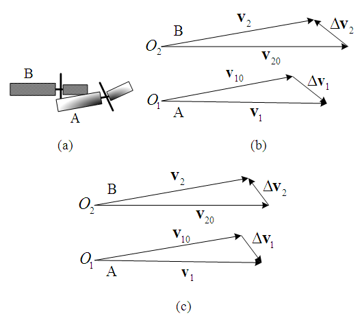 | Figure 8. Illustration diagram and velocity triangles of situation (a) |
Situation (b): right-deviating motorcycle B collides with straight-moving motorcycle A.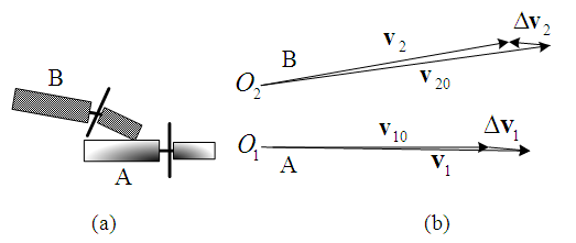 | Figure 9. Illustration diagram and velocity triangles of situation (b) |
The illustration diagram is shown as Figure 9(a). Using a similar procedure as in situation (a), the velocity triangles of motorcycles A and B can be drawn as shown in Figure 9(b), in which the pre-impact velocity  points to the upper-right direction, meaning that motorcycle B is left-deviating and not right-deviating. Hence, situation (b) is wrong.Situation (c): right-deviating motorcycle B collides with left-deviating motorcycle A.
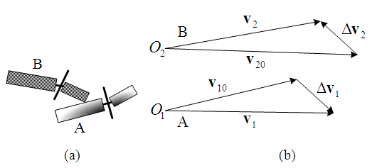 | Figure 10. Illustration diagram and velocity triangles of situation (c) |
The illustration diagram is shown as Figure 10(a). The velocity triangles can be drawn as Figure 10(b) in which motorcycle A is deviating to the left and motorcycle B is deviating to the right. Hence, situation (c) is correct.Situations (a) and (c) can both be correct. It can be further judged by the falling directions of the two motorcycles after the collision.In situation (a), the left side of the front and rear assemblies of motorcycle A is obliquely hit by motorcycle B, which causes the handlebar of motorcycle A to turn to the right. Referring to Table 1, motorcycle A falls to the left (turned right, falls left). The front end of motorcycle B hits the left side of motorcycle A. Therefore, the handlebar of motorcycle B is turned to the left which causes motorcycle B to fall to the right (turned left, falls right). The falling directions of motorcycles A and B are the same as those shown in the accident diagram.In situation (c), the left side of motorcycle A’s rear assembly is hit, it should fall to the right (left hit, falls right), however, motorcycle A falls to the left in the accident diagram. Moreover, the lower probability of motorcycle A is deviating to the left while motorcycle B is deviating to the right simultaneously. Hence, situation (a) is more likely the correct scenario.Example 2: motorcycles A and B were traveling from the right to the left and fell to the ground in the opposite lane. The accident diagram is shown in Figure 11.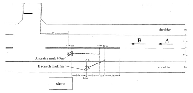 | Figure 11. Accident diagram of Example 2 [8] |
According to the photos and information provided by the police, the collision occurred at the front end of motorcycle A and the rear end portion of motorcycle B.Since the ground scratch marks are all in the opposite lane of the road and the scratch mark of motorcycle B is very oblique, there may have three possible impact situations.Situation (a): left-turning motorcycle A moves faster and collides with straight-moving motorcycle B.The illustration diagram is shown in Figure 12(a). Based upon the length and direction of the ground scratch mark of motorcycle B, draw a vector from reference point  to represent the post-impact velocity
  . Because motorcycle B goes straight, draw a vector with adjustable length from point
  to the left to represent its pre-impact velocity
  . Motorcycle A hits motorcycle B along the lower-left direction. Hence, the direction of impact velocity change
  is toward the lower left. Draw a vector from the tip of
  toward the lower-left direction to the tip of
  to represent
  . The velocity triangle of motorcycle B is shown in Figure 12(b). Since both of motorcycles are scooters, they have similar mass. The relationship of
  is applied to construct the velocity triangle of motorcycle A as shown in Figure 12(b). The post-impact velocity
  is toward to the lower-left direction in Figure 12(b), while the direction of ground scratch mark of motorcycle A points to the upper left in the accident diagram. Moreover, the length of
  is shorter than that of
  in the velocity triangle, while the ground scratch mark of motorcycle A is longer than that of motorcycle B in the accident diagram. Therefore, situation (a) is incorrect.
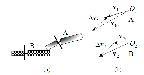 | Figure 12. Illustration diagram and velocity triangles of situation (a) |
Situation (b): straight-moving motorcycle A moves faster to collide with left-turning motorcycle B in the opposite lane.The illustration diagram is shown in Figure 13(a). Since motorcycle A goes straight, draw a vector with adjustable length from point  to the left to represent its pre-impact velocity
  . From Figure 13(a), the impact velocity change of motorcycle A is toward the lower-right direction. Draw a vector from the tip of
  along the lower-right direction with adjustable length to represent the
  . Then connect
  to the tip of
  , completing the velocity triangle of motorcycle A, as shown in Figure 13(b) in which the direction of
  is not the same as that of the ground scratch mark of motorcycle A in Figure 11. Hence, situation (b) is incorrect.
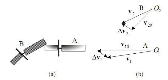 | Figure 13. Illustration diagram and velocity triangles of situation (b) |
Situation (c): when motorcycle A tries to overtake motorcycle B from the left side of the road and motorcycle B suddenly turns to the left. Then, motorcycle A dodges to the right and hit the rear portion of motorcycle B.The illustration diagram is shown in Figure 14(a). The velocity triangles of motorcycles A and B are shown in Figure 14(b) in which the magnitudes and directions of  and
and  are consistent with the lengths and directions of the ground scratch marks of motorcycles A and B, respectively. The
  points to the upper-left direction which means that motorcycle A tries to overtake and switch to the right. The direction of
  points downward at a large angle to the left which means that motorcycle B is turning left. In addition, the handlebar of motorcycle A is turned to the left after the collision due to the normal impact force
  and tangential impact force
  as shown in the force diagram of Figure 14(c). Referring to Table 1, motorcycle A falls to the right (turned left, falls right). The motorcycle B is hit on the left side of the rear assembly, and the normal impact force
  causes it to fall to the right (left hit, falls right). In the accident diagram, both motorcycles fall to the right, and the falling directions are the same as the theoretical ones. Therefore, situation (c) is correct.
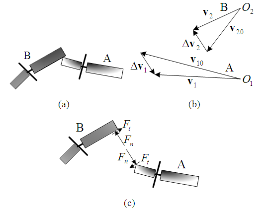 | Figure 14. Illustration, velocity triangles and force diagrams of situation (c) |
The scenario of situation (c) is possibly due to the road not being wide enough. When motorcycle A crosses the centerline by trying to overtake motorcycle B, which happens to suddenly turn left to go to the store in the opposite side of the road. Then the motorcycle A dodges to the right and collides with the rear end portion of motorcycle B.Example 3: determine whether the moving directions of the two motorcycles before the collision shown in Figure 15 are correct or not. 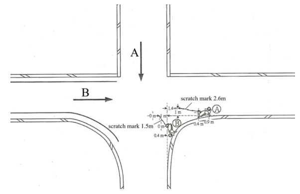 | Figure 15. Accident diagram of Example 3 [8] |
According to the photos and information provided by the police, the collision occurred at the front end of motorcycle B and the right front assembly of motorcycle A. The illustration and force diagrams are shown in Figures 16(a) and 16(b), respectively. The velocity triangles of motorcycles A and B can be drawn as Figure 16(c). The post-impact velocities  and
and , as well as the pre-impact velocities
  and
and  match the ground scratch marks and the moving directions of motorcycles A and B in the accident diagram. Moreover, the normal impact force
  causes the handlebar of motorcycle A to turn to the left and it falls to the right (turned left, falls right). The tangential impact force
  causes the handlebar of motorcycle B to turn to the right and it falls to the left (turned right, falls left) as described in Table 1. The falling directions of both motorcycles in the accident diagram also match the theoretical falling directions. Hence, the moving directions of motorcycles A and B before the collision in the accident diagram are correct.
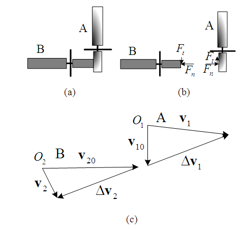 | Figure 16. Illustration and force diagrams, and velocity triangles of example 3 |
4. Sideswipe Accident
Sideswipe accidents tend to occur when motorcycles A and B move in the same direction and one of them deviates or turns to left or right. These collisions are very common in Taiwan where scooters and lightweight motorcycles are primarily driven. Since the difference in mass between scooters and lightweight motorcycles is small, the velocity change  is applied in the following analysis.Using the illustration diagram shown in Figure 3 and depending on the impact force as well as the deviation or turning angle, the velocity triangles for the straight-moving motorcycles A that move faster than the left-deviating or left-turning motorcycles B are shown in Figure 17.In Figures 17(a) and 17(b), velocities
  point to the lower-right direction (that is ground scratch marks of motorcycles B point to the front right in relation to the straight-moving direction). This is because motorcycles B deviate to the left or turns left with small angles or the impact forces are large. Velocities
  point to the upper-right direction in Figures 17(c) and 17(d) indicate that the ground scratch marks of motorcycles B point to the front-left direction of the road due to the larger angles of the left-deviating or left-turning motorcycles B or theirs small impact forces.
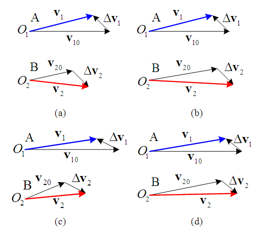 | Figure 17. Velocity triangles of the straight-moving motorcycles A move faster than the left-deviating or left turning motorcycles B |
Similarly, the velocity triangles of the left-deviating or left-turning motorcycles B which move faster to collide with the straight-moving motorcycles A are shown in Figure 18.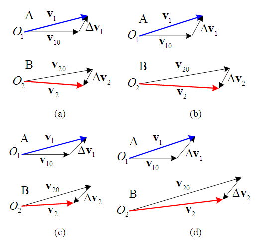 | Figure 18. Velocity triangles of the left-deviating or left-turning motorcycles B move faster than the straight-moving motorcycles A |
In Figures 17 and 18, the angle of velocity  relative to a straight-moving direction is bigger compared to the corresponding angle of velocity
  . This implies that the ground scratch marks of the straight-moving motorcycles are more oblique than those of the left-deviating or the left-turning motorcycles. Figure 19 has three accident diagrams that validate the conclusion.
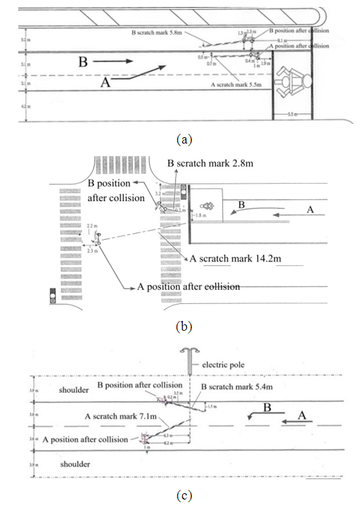 | Figure 19. The ground scratch marks of straight-moving motorcycles are more oblique than those of the left-deviating or left-turning motorcycles [8] |
Similarly, the ground scratch marks of the straight-moving motorcycles are more oblique than those of the right-deviating or right-turning motorcycles. Figure 20 has three accident diagrams that support the conclusion.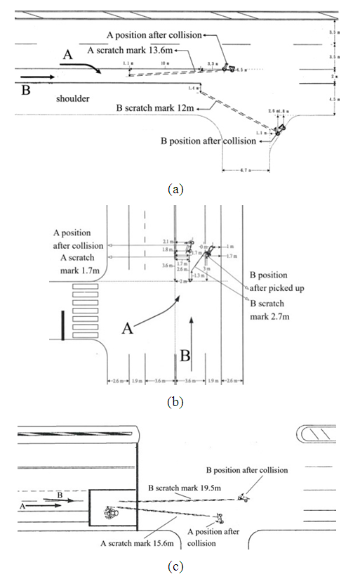 | Figure 20. The straight-moving motorcycles’ ground scratch marks are more oblique than those of the right-deviating or right-turning motorcycles [8] |
From Figures 17 to 20, we can conclude that in a sideswipe collision between two motorcycles with small mass difference moving in the same direction, the ground scratch mark of the straight-moving motorcycle is more oblique than the one caused by the motorcycle that deviates or turns to the left or right. For examples, in Figure 21(a), motorcycle A is going straight and motorcycle B is left-deviating due to the ground scratch mark of motorcycle A is more oblique. In Figures 21(b), 21(c) and 21(d), motorcycles B are moving straight and motorcycles A are deviating to the left because the ground scratch marks of motorcycles B are more oblique. 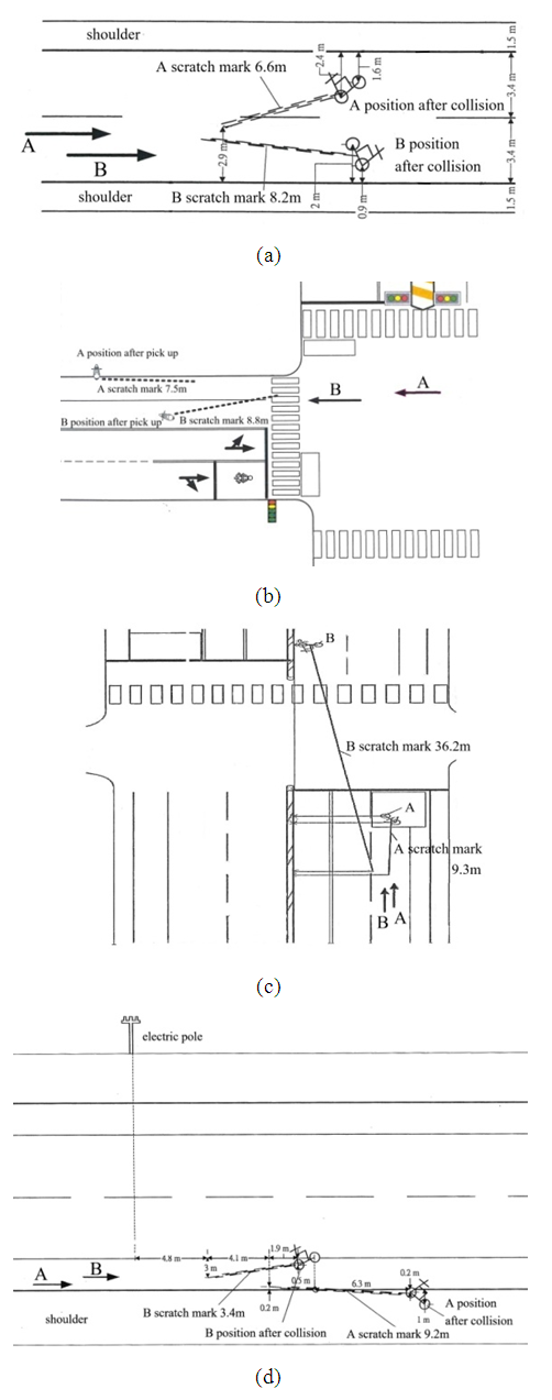 | Figure 21. Motorcycles are left-deviating based on the inclination of the ground scratch marks [8] |
In Figure 22(a), since the ground scratch mark of motorcycle B is more oblique, motorcycle B is going straight and motorcycle A is right-deviating. In Figure 22(b), because the ground scratch mark of motorcycle A is more oblique, motorcycle A is moving straight and motorcycle B is deviating to the right.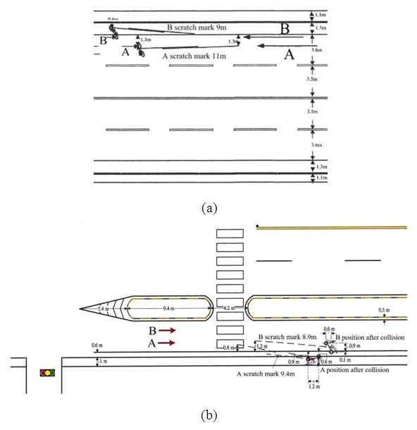 | Figure 22. Using the inclination of the ground scratch marks to quickly determine which motorcycle is right-deviating [8] |
Note that the above conclusion is not applicable if the mass difference between two vehicles is large. For examples, a motorcycle collides with a bicycle, or a large heavy-duty motorcycle collides with a scooter. In these cases to draw the velocity triangles for analysis are necessary.
5. Conclusions
A new method to estimate two motorcycles’ moving directions before a collision by using their ground scratch marks is presented. Three vectors, namely, pre-impact velocity, impact velocity change, and post-impact velocity form an impact velocity triangle (abbreviated as “velocity triangle”) for each motorcycle in which the moving directions of two motorcycles before the collision can be estimated. The magnitude and direction of the impact velocity change is analyzed in detail. The steps to draw the velocity triangle of each motorcycle are introduced and explained with real accident cases in the examples.Detail analysis procedure to estimate the moving directions of two motorcycles before collision with three accident diagrams in Taiwan are illustrated to prove the method is feasible. Sometimes, there may be more than one reasonable assumed impact situation for pre-impact directions. Then, using the falling directions of the motorcycles can further confirm the correct pre-impact directions.When a sideswipe collision happens between two motorcycles with similar masses moving in the same direction, the ground scratch mark of the straight-moving motorcycle is more oblique than that of the left or right-deviating or turning motorcycle. This conclusion can allow identification personnel to quickly determine which motorcycle is going straight, which is deviating or turning to the left or the right.The application of the method presented in this article is based on tracing the ground scratch marks of the two motorcycles after a collision occurs. Since most motorcycles in Taiwan and Southeast Asia are lightweight scooters and street motorcycles, their average traveling speed is not very fast. Therefore, when a collision happens between two motorcycles, both vehicles usually leave ground scratch marks as they fall. However, this method may not be applicable when heavy-duty motorcycles collide at higher speeds. Because heavier motorcycles are more stable and they may roll out of road margins instead of falling immediately to create ground scratch marks. Since this paper only applies simple dynamics theories, the method can be used by relevant personnel who have basic knowledge of dynamics to estimate the moving directions of two motorcycles right before a crash. It is practical and useful in motorcycle accident reconstruction.
ACKNOWLEDGEMENTS
Special thanks to Tainan City Traffic Accident Investigation Committee in Taiwan for providing the accident diagrams and appraisal cases used in this article.
References
| [1] | D. P. Wood, C. Glynn and D. Walsh, “Motorcycle-to-Car and Scooter-to-Car Collision: Speed Estimation from Permanent Deformation,” Proceedings of the Institution of Mechanical Engineers: Journal of Automobile Engineering, vol. 223, pp. 737-756, 2009. |
| [2] | B. F. McNally and W. Bartlett, “Motorcycle Speed Estimates Using Conservation of Linear and Rotational Momentum,” The 20th Annual Special Problems in Traffic Crash Reconstruction at the Institute of Police Technology and Management, University of North Florida, 2002. |
| [3] | K. S. Obenski and P. F. Hill, Motorcycle Accident Reconstruction and Litigation, 3rd ed., Tucson: Lawyers & Judges Publishing Company, 2002. |
| [4] | N. Rose, Motorcycle Accident Reconstruction, 2nd ed., Wallendle: SAE International, 2022. |
| [5] | O. Masory, W. Bartlett and B. Wright, “Motorcycle Accident Reconstruction, Part 1-Physical Models,” Florida Conference on Recent Advances in Robotics, 2012. |
| [6] | C. C. Chang, “Falling Direction of Motorcycle and Its Application in Traffic Accident Reconstruction,” SAE International Journal of Transportation Safety, vol. 11, pp. 37-53, 2023. |
| [7] | F. P. Beer and E. R. Johnston Jr., Vector Mechanics for Engineering: Dynamics, 3rd SI Metric ed., New York: McGraw-Hill, 1999. |
| [8] | Accident Diagrams in Tainan City Traffic Accident Investigation Committee, Taiwan. |


 generated by the collision that causes the momentum change
  can be written as
 is the result impact force of the collision. Using Equation (1), the impact velocity change
  of motorcycle A can be expressed as
 is the system mass of motorcycle A,
  is the pre-impact velocity of motorcycle A and its direction is the same as that of motorcycle A moving before the collision. The
  is the post-impact velocity of motorcycle A and its direction is the sliding direction of motorcycle A after the collision which leaves scratch mark with length
  on the ground. Equation (2) can be rewritten as

 is the pre-impact velocity of motorcycle B and its direction is the same as motorcycle B’s moving direction before the collision,
  is the post-impact velocity of motorcycle B and its direction is the moving direction of motorcycle B after the collision which leaves ground scratch mark of length
  , and
, and  is the impact velocity change of motorcycle B.The
 and
and  constitute the impact velocity triangle of motorcycle A, while the
 and
and  form the impact velocity triangle of motorcycle B as shown in Figure 2. In this paper, impact velocity triangle is abbreviated as “velocity triangle”. The steps to draw the velocity triangles will be explained in Section 2.5.

 is the system mass of motorcycle B. Substituting Equations (3) and (4) into Equation (5), the relationship between the two impact velocity changes can be written as
 . The majority of motorcycles in Taiwan are scooters and lightweight street motorcycles. Their mass differences are small. Hence, when drawing the impact velocity changes in the velocity triangles, they can be drawn as equal in length but opposite in direction.
  perpendicular to the collision surface and an equivalent tangential impact force
  along the collision surface are generated at the collision area, and their resultant impact force and impulse are F and I, respectively. The impact velocity change is caused by the resultant impulse I, hence its direction is the same as that of the resultant impact force F. Using a straight-moving motorcycle A collides with motorcycle B that deviates from straight to the left shown in Figure 3 as an example. Assume that motorcycle A moves faster than motorcycle B. The impact force diagrams (abbreviated as “force diagrams”) of motorcycles A and B are shown in Figure 4. In Figure 4(a), the front right corner of motorcycle A collides with the left side of motorcycle B. The equivalent normal impact force
  is perpendicular to the left side of motorcycle B. The contact area of motorcycle A slides to the upper-right direction along the left side of motorcycle B, hence the equivalent tangential impact force
  goes along the left side of motorcycle B pointing to the upper-right direction. Applying Newton’s third law of motion, there are
  and
and  with opposite directions acting on motorcycle A, and their resultant impact forces F are shown in Figures 4(b) and 4(c).


 ) is along the oblique front direction of the collision place of motorcycle B as shown in Figure 4(c). If the left-deviating motorcycle B is traveling faster when it hits the straight-moving motorcycle A, the direction of the impact velocity change
  of motorcycle B goes along the diagonal rear direction of the collision place of motorcycle B as shown in Figure 5(c).
 and
and  as reference points. According to the lengths and directions of the ground scratch marks of motorcycles A and B, draw two vectors from points
  and
and  to represent the post-impact velocities
  and
and  of motorcycles A and B, respectively as shown in Figure 2.3. Draw the motorcycle that moves straight first. Since motorcycle A goes straight to the right, draw a vector from point
  to the right with adjustable length to represent the pre-impact velocity
  . Using the analysis in Section 2.4, motorcycle A hits the left side of motorcycle B at a faster speed, then the direction of the impact velocity change of motorcycle A is towards the upper left (see Figure 4(c)). Hence, draw a vector from the tip of
  with the upper-left direction to the tip of
  to represent
  . The velocity triangle of motorcycle A is completed as shown in Figure 2.4. For motorcycle B, the impact velocity change
  can be accurately obtained by applying Equation (6). If the mass difference of two motorcycles is small, then
  , and
, and  can be applied. Hence, draw from the tip of
  with
with  . Then connect
  to the starting point of
  to represent the pre-impact velocity
  and the velocity triangle of motorcycle B is completed as shown in Figure 2.


 and
and  to represent the post-impact velocities
  and
and  , respectively. Since motorcycle B goes straight from left to right, draw a horizontal vector from point
  to the right with its length adjustable to represent the pre-impact velocity
  . The direction of the impact velocity change
  goes toward the upper left. Connect from the tip of
  toward the upper-left direction to the tip of
  , completing the velocity triangle of motorcycle B as shown in Figure 8(b).Since both motorcycles are scooters, their mass difference is small. Referring to Section 2.3, the impact velocity change of motorcycle A is
  . Hence, draw from the tip of
  with a vector
  , then connect point
  to the tail of
  to represent the pre-impact velocity
  . The velocity triangle of motorcycle A is completed as shown in Figure 8(b).In the velocity triangles, the magnitudes and directions of
  and
and  are consistent with the lengths and directions of motorcycle A’s and B’s ground scratch marks, respectively. The
  points to the upper-right direction which is in keeping with the left-deviating of motorcycle A. The direction of
  is toward the straight right that matches with the assumption of the straight-moving motorcycle B. Therefore, situation (a) is correct.Note that the speed and left-deviating angle of motorcycle A as well as the speed of motorcycle B before the collision do not need to be considered accurately. Therefore, when drawing the velocity triangles,
  and
and  can be adjustable in lengths or directions to obtain different velocity triangles. For example, the velocity triangles shown in Figure 8(c) are also corresponding to situation (a).

 points to the upper-right direction, meaning that motorcycle B is left-deviating and not right-deviating. Hence, situation (b) is wrong.Situation (c): right-deviating motorcycle B collides with left-deviating motorcycle A.

 to represent the post-impact velocity
  . Because motorcycle B goes straight, draw a vector with adjustable length from point
  to the left to represent its pre-impact velocity
  . Motorcycle A hits motorcycle B along the lower-left direction. Hence, the direction of impact velocity change
  is toward the lower left. Draw a vector from the tip of
  toward the lower-left direction to the tip of
  to represent
  . The velocity triangle of motorcycle B is shown in Figure 12(b). Since both of motorcycles are scooters, they have similar mass. The relationship of
  is applied to construct the velocity triangle of motorcycle A as shown in Figure 12(b). The post-impact velocity
  is toward to the lower-left direction in Figure 12(b), while the direction of ground scratch mark of motorcycle A points to the upper left in the accident diagram. Moreover, the length of
  is shorter than that of
  in the velocity triangle, while the ground scratch mark of motorcycle A is longer than that of motorcycle B in the accident diagram. Therefore, situation (a) is incorrect.
 to the left to represent its pre-impact velocity
  . From Figure 13(a), the impact velocity change of motorcycle A is toward the lower-right direction. Draw a vector from the tip of
  along the lower-right direction with adjustable length to represent the
  . Then connect
  to the tip of
  , completing the velocity triangle of motorcycle A, as shown in Figure 13(b) in which the direction of
  is not the same as that of the ground scratch mark of motorcycle A in Figure 11. Hence, situation (b) is incorrect.
 and
and  are consistent with the lengths and directions of the ground scratch marks of motorcycles A and B, respectively. The
  points to the upper-left direction which means that motorcycle A tries to overtake and switch to the right. The direction of
  points downward at a large angle to the left which means that motorcycle B is turning left. In addition, the handlebar of motorcycle A is turned to the left after the collision due to the normal impact force
  and tangential impact force
  as shown in the force diagram of Figure 14(c). Referring to Table 1, motorcycle A falls to the right (turned left, falls right). The motorcycle B is hit on the left side of the rear assembly, and the normal impact force
  causes it to fall to the right (left hit, falls right). In the accident diagram, both motorcycles fall to the right, and the falling directions are the same as the theoretical ones. Therefore, situation (c) is correct.

 and
and , as well as the pre-impact velocities
  and
and  match the ground scratch marks and the moving directions of motorcycles A and B in the accident diagram. Moreover, the normal impact force
  causes the handlebar of motorcycle A to turn to the left and it falls to the right (turned left, falls right). The tangential impact force
  causes the handlebar of motorcycle B to turn to the right and it falls to the left (turned right, falls left) as described in Table 1. The falling directions of both motorcycles in the accident diagram also match the theoretical falling directions. Hence, the moving directions of motorcycles A and B before the collision in the accident diagram are correct.
 is applied in the following analysis.Using the illustration diagram shown in Figure 3 and depending on the impact force as well as the deviation or turning angle, the velocity triangles for the straight-moving motorcycles A that move faster than the left-deviating or left-turning motorcycles B are shown in Figure 17.In Figures 17(a) and 17(b), velocities
  point to the lower-right direction (that is ground scratch marks of motorcycles B point to the front right in relation to the straight-moving direction). This is because motorcycles B deviate to the left or turns left with small angles or the impact forces are large. Velocities
  point to the upper-right direction in Figures 17(c) and 17(d) indicate that the ground scratch marks of motorcycles B point to the front-left direction of the road due to the larger angles of the left-deviating or left-turning motorcycles B or theirs small impact forces.

 relative to a straight-moving direction is bigger compared to the corresponding angle of velocity
  . This implies that the ground scratch marks of the straight-moving motorcycles are more oblique than those of the left-deviating or the left-turning motorcycles. Figure 19 has three accident diagrams that validate the conclusion.


 Abstract
 Reference
 Full-Text PDF
 Full-text HTML