Slivinskii Е. V., Korchagin V. A., Radin S. Yu., Rizayeva Yu. N.
Yelets State University I. A. Bunin, Lipetsk state technical university
Correspondence to: Slivinskii Е. V., Yelets State University I. A. Bunin, Lipetsk state technical university.
| Email: |  |
Copyright © 2015 Scientific & Academic Publishing. All Rights Reserved.
Abstract
This article presents the material relating to the development of advanced designs of devices aimed at improving safety in the maintenance and repair of dump full trailers transported as part of automotive trains. The proposed technical solutions created at the inventions allow more safely and effectively perform repair and maintenance work components and assemblies in the trailers when they are in a buoyant body condition. Calculations of force loading of structural elements of a number of these devices will prove the basic rational geometrical parameters of such structures. Recommended the development, both domestic and foreign research and industrial structures in the field of Automobile and Tractor Engineering for their further study and possible implementation in practice.
Keywords:
Trailer, Tractor, Frame, Longeron, Hydraulic jack, Cross-piece, Reference device, Spring, Rigidness, Tension
Cite this paper: Slivinskii Е. V., Korchagin V. A., Radin S. Yu., Rizayeva Yu. N., Modernization of Bodies Tipper Trailers to Improve the Working Conditions of Maintenance, International Journal of Traffic and Transportation Engineering, Vol. 4 No. 2, 2015, pp. 35-44. doi: 10.5923/j.ijtte.20150402.01.
1. Introduction
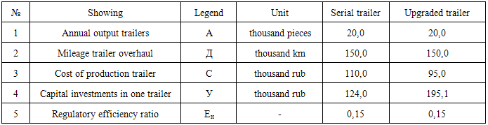
Increase of safety of service of agricultural machines is one of the major tasks on enhancement of agricultural production in our country. The successful solution of problems of support of safe maintenance and reliability of machines in operation, saving of metal and lightness of constructions probably only on the basis of the theory and application in practice of design of the modern methods and funds of calculation for durability, wear resistance and rigidness. One of the major technological processes, for example, in an agronomical complex are transport operations on transportation of different loads to what different trucks and the autotractor trains consisting of tractors of aggregated with trailers and semi-trailers are widely applied. The broadest application is found by tractor transport. As tractors to transportation of trailers and semi-trailers apply wheel tractors of a class 0,9t, such as a tractor four-wheel T-28X4M-C1 and T-40AM. Wheel tractors of a class of 1,4 t it is the MTZ-52, MTZ-80, YuMZ-6M tractors, etc. Constructions of tractor dumping trailers are also diversiform and generally it is tractor biaxial dumping trailers of models 2PTS-4-793-01, 2PTS-4-887, 2-PTS-4M, and also heavy-load tractor semi-trailers of model 3-PTS-12 with a loading capacity of 12,0 t aggregated with the wheel K-700 tractors, etc. [1-3]. Basis of construction of all tractor trailers is the chassis which serves for installation on it of a platform and adaptations.Usually in the package of the chassis are included: frame, running gear, the tractive coupling device, the brake system, the rolling-over mechanism and electric equipment (fig. 1). The frame of the trailer represents welded construction and consists of two stamped longerons connected among themselves cross-pieces. In a middle part of a frame by means of a support bracket the lower support of a hydraulic jack is welded. When trailers are involved in transportation of light-weight loads of their platform are supplied with the added side folding and stationary edge boards having under operating conditions low reliability. Usually at all models of autotractor dumping 2PTS-4 trailers hydraulic jacks are executed telescopic type from steel pipes entering each other. For the purpose of increase of safety of service and repair of nodes and details of the trailers which are in hard-to-reach spots, they are supplied with safety stands of platforms. Usually in the package of the chassis are included: frame, running gear, the tractive coupling device, the brake system, the rolling-over mechanism and electric equipment (fig. 1). The frame of the trailer represents welded construction and consists of two stamped longerons connected among themselves cross-pieces. In a middle part of a frame by means of a support bracket the lower support of a hydraulic jack is welded. When trailers are involved in transportation of light-weight loads of their platform are supplied with the added side folding and stationary edge boards having under operating conditions low reliability. Usually at all models of autotractor dumping 2PTS-4 trailers hydraulic jacks are executed telescopic type from steel pipes entering each other. For the purpose of increase of safety of service and repair of nodes and details of the trailers which are in hard-to-reach spots, they are supplied with safety stands of platforms.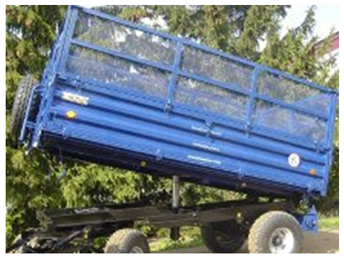 | Figure 1. General view of the autotractor dumping trailer model 2PTS-4 |
Essential lack of such safety stands is that they are set manually and in practice often the service personnel, having forgotten them to set, is subject to traumatizing at the expense of a possible self-omitting of a body because of existence of possible defects in tractor and trailer hydraulic systems.Therefore, in practice, ways on creation and use are found now, different devices on construction allowing to mechanize process set also dismantling of safety stands operating in an automatic mode.Considering it the budgetary NIR is carried out to Yelets State University I.A.Bunin on chair of mechanics and technological processes throughout a row of years on the subject "Dynamics, Durability and Reliability of Transport, Construction and Road and Agricultural Machines, and also the Industrial Normal and Non-standard Equipment in relation to the Chernozem Region of the Russian Federation" and to one of its sections researches directed on improving of working conditions of the service personnel taken are executed in case of their maintenance.
2. Research Objective
Given the above objective of this study is:1. Development of advanced designs at inventions devices for automatic locking body in high state to make maintenance work during servicing of automotive tipper trailers.2. Development of design schemes such device allows calculations to determine the rational of their kinematic and geometric parameters.3. Evaluation of technical and economic efficiency of the proposed technical solutions for possible introduction in the last practice.
3. Research Technique
Analysis of numerous number of bibliographic sources, as well as domestic and foreign patents, allowed to develop at the level of invention (RU2463179) technical solution to automatically capture platform trailer with a tilt of her state for unloading.Figure 2 shows a general view of the hydraulic ram tipper tractor trailer in the section.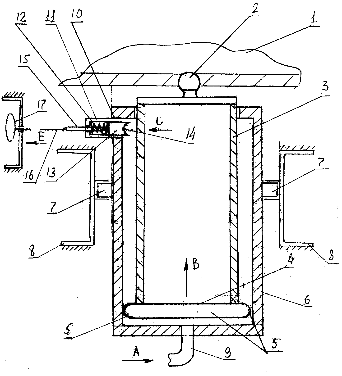 | Figure 2. |
Tipper Tractor trailer consists of tipper platform 1 (completely trailer not shown) pivotally interconnected with the help of leg 2 rigidly attached to the inner tube 3 hydraulic ram. In its lower part the inner tube 3 is provided with bottom 4 which on its circular generatrix has a convex hemispherical surface 5. Inner tube 3 is movably arranged in the outer tube 6 hydraulic ram which, by means of hinges 7 mounted on the frame beam 8, the chassis of the vehicle tipping. In the lower portion of the outer tube 6 is connected to the inlet 9 of the hydraulic system of the tractor. In the upper portion of the outer tube 6, a groove 10 arranged therein and is rigidly there to mounting body 11 which is movably mounted in a spring-loaded by a compression spring 12 having a cotter 13 at its end portion a hemispherical concave surface 14. Itself cotter 13 via rod 15 is connected to a flexible bond 16 with the handle 17 fixed at the end portion of the chassis frame of the tipper vehicle.Powered Dumper vehicle follows. When unloading platform 1 tipper vehicle, well known in the art process, is fed under pressure from the working fluid by the arrow A (Fig. 2), whereupon the inner tube 3 is moved according to the arrow B until the convex hemispherical surface 5 bottom 4 does not come into contact with the cotter 13. Thus cotter 13 will move according to arrow C, elastically deforming the compression spring 12, thereby providing further movement of the inner tube 3. Once convex hemispherical surface 5 of the bottom 4 comes into contact with a hemispherical concave 14 cotter surface 13, the process of movement of the inner tube 3 stops and under the force generated by the compression spring 12, the cotter 13 securely holds inner tube 3. After unloading dump platform 1, the operator manually moves the handle 17 along arrow E, which facilitates the movement of cotter 13 in same direction as it by means of a flexible rod 15 and the connection 16 is connected to the handle 17. Such action creates a condition for the output of the hemispherical contact surfaces 5 and 14 and hence the inner tube 3 is able to move in the direction opposite the arrow B, displacing working fluid in the inlet 9. After lowering dump platform 1, all items devices occupy a position as shown in Figure 2. Further, the described process can be repeated many times.Analyzing the above structure hydraulic ram (Fig. 2) shows that the structural component of the charge it is a cotter 13, which interacts with the bottom 4 and retention platform trailer inclined state exposed slice. Given the latter, the inspections strength cracker considering that it is made of rectangular cross section and are known as its geometrical dimensions (height h = 35,0 mm and width b =25,0 mm), and load Q = 965 kg = 9650 N attached to it by its own weight platform tractor tipper trailer 2РТS-4-793А. For this we use the following well-known dependence: when, S0 – static moment about the neutral axis x of the square-section lying on one side at the level at which the voltage is determined and is equal to S0 = b/2(h2/4 – y2);
  for steel 45, which is made of a cracker.It is evident that the strength condition is satisfied and its stock is 3,1.Consider another solution also recognized the invention (RU2481971) and directed as well as previous to improve the safety of the work in the operation of a tractor trailer tipper dump it in terms of discharge.So in Figure 3 shows a general view of the tipper vehicle side, it hydrolift sectional and part of the fixing assembly hydraulic ram.
 | Figure 3. Technical solution for patent RU2481971 |
Dumper In this case the vehicle comprises a chassis 1 platform 2. On the chassis 1 and the platform 2 by means of ball joints 3 and 4 located telescopic hydraulic hoist, comprising cylindrical housing 5 rigidly fixed to the inner pipe 6. Cylindrical casing 5 adjustably positioned relative to the outer pipe 7, and between it and the inner tube 6 is arranged an intermediate tube 8. Outer tube 7 is provided with a conduit 9, and a cylindrical shaped casing 5, a groove 10 in which the finger 11 is movably arranged rigidly attached to one arm of the threearms lever 12 by a hinge 13 mounted on the outer surface of the cylindrical housing 5. Other arm of the threearms lever 12 is contacted by the compression spring 14 with the outer cylindrical surface of the casing 5, and one of the arms of threearms 12 by elastic coupling 15, and springs extension 16 is attached to the handlebar 17 by the finger 11.Powered Dumper vehicle follows. For unloading platform 2 is widely known in the art similar manner according to the arrow A is supplied hydraulic fluid under pressure into the conduit 9 and the last entering the outer tube 7, promotes the movement of the inner tube 6 by the arrow B, but since inner tube 6 is rigidly connected to a cylindrical shape a casing 5, and then it is together with the ball joint 3 moves in this same direction lifting the platform 2 by the arrow C. When driving cylindrical casing 5 by the arrow B, its finger 11 slips on the outer peripheral surface of the tube 7 and, finally, comes a moment when he stops in contact, being outside it with the latter and then, under the action of compression spring 14, it will move along arrow E being above the end surface of the outer tube 7. Subsequently the inner tube 6 with its base is in contact with the end the intermediate part of the tube 8, which provides its movement in the same direction of arrow C until it also when its lower part comes into contact with the end portion of the outer tube 7. Such contact corresponds to full extension of the outer tube 7 as the intermediate tube 8 and inner tube 6. Simultaneously, described the movement of pipes 7 and 8 commits and moving together with them in the same direction and cylindrical shaped casing 5 with finger 11 with it continues to move in direction of arrow C. The process described in the end provide tipper unloading platform 2 that receives the inclined towards the unloading of bulk cargo and when it is completely free from the latter , the operator commonly known method for this type of machines connect to the hydraulic line 9 of the tractor (in the drawings it is not shown) at the outlet. This operation will allow the return of the platform 2 in the direction opposite to the arrow C. It will continue until the standpipe until the finger 11 moving together with the cylindrical housing 5, opposite to the arrow K, rests on the end surface of the outer pipe 7, and thereby the movement of cylindrical housing 5 and, hence, the platform 2 is stopped. In this case, the wait staff can carry out various repairs or maintenance work under the raised platform 2, except for the last possible injuries. After repairs , the operator control handle 17 translates according to arrow M, and then the finger 11 moves in the direction opposite the arrow E by releasing fixation cylindrical casing 5, relative to the outer tube 7, and, consequently, the platform 2 is lowered onto the chassis 1 trailer occupying such position, as shown in Fig.1. Hereinafter described processes tilt platform 2 and its descent into the transport position may be repeated several times.Analyzing such a design hydraulic ram (Fig. 3) shows that the structural component of its charge as well as in the previous technical solution is a finger 11 which interacts with the outer tube 7 being located in a cylindrical shaped housing 5 platform holding the trailer in an inclined position and thus susceptible to shear. Considering the latter, we believe that it is made in a similar manner as shown in Figure 2, i.e. rectangular cross section and is known for its geometric dimensions (height h = 35,0 mm and breadth b =25,0 mm), under the same load Q = 965 kg = 9650 N attached to it by its own weight platform tractor tipper trailer 2PTS-4-793А. Consider another technical solution aimed at improving the safe operation when operating the tractor tipper trailer tipper unloading conditions of the invention is also recognized RU2314941.So in Figure 4 shows a side view of the trailer and part of the cross-section at the location of the hydraulic ram body.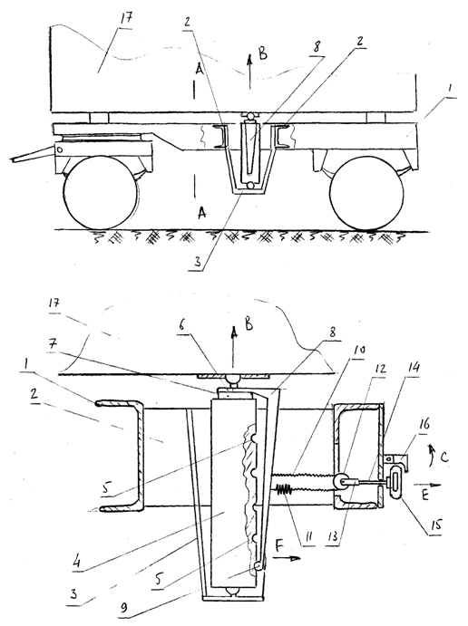 | Figure 4. Technical solution for patent RU2314941 |
The trailer consists of a frame 1 to crossbars 2 which is rigidly attached support bracket 3 of hydraulic ram. The outer tube 4 made hydraulic ram hemispherical recesses 5. By the end surface 6 of the inner pipe 7 is connected hydraulic lift severely elastic plate 8 provided with a projection at its end 9. By the elastic plate 8 on one side rigidly attached flexible connection 10, and on the other but it is also by means of a tension spring 11. Flexible connection 10 slung over block 12 which is movably mounted in the clevis 13 and the last tough using traction 14, is connected to the handle 15 relative to the frame 1 lockable latch 16. Inner tube 7 of hydraulic lift hinged to platform 17.To dump unloading platform 17 is widely known in the art way to create a fluid pressure, and it enters the hydraulic ram, the inner pipe 7 starts to move in the direction of arrow rotating body with respect to its supports on the frame in the right, left or rear side (typically operate triangular platform unloading). Such movement of the inner pipe 7 also contributes to the hydraulic ram displacement in the same direction of the elastic plate 8, which with its projection 9 slides on the outer surface of the outer tube 4 periodically in utaplivaja hemispherical recesses 5. Described process of motion of the elastic plate 8 occurs before until it 9 protrusion engages with the last adjustment hydraulic ram hemispherical recess 5. Further extension of the inner tube 7 stops by limiting its movement due to a design feature of hydraulic elevator. The described movement of the inner pipe 7 and also contributes tensioning flexible coupling 10, which follows the stretching of the elastic plate 8, the spring 10 on the rolling block 12. After precipitation of the cargo tractor body 17 is also widely known in the art, the hydraulic distributor of the tractor by means of a hydraulic ram connects the drain backbone, creating the conditions for lowering the body 17 on frame 1. However, this does not happen due to reliable fixing of the inner tube 7, the protrusion 9, which is in contact with the top spherical shape of the recess 5, the outer tube 4 of the hydraulic ram. In other words, fixing body 17 is reliable and can, if necessary, to carry out repair and maintenance work hard knots trailer without fear Self-start platform 17. To lower the platform 17 to the frame 1, move the latch 16 by arrow C and push the handle 15 along arrow E, which entrains the rod 14 with the block 15, thereby elastically deforming the elastic plate 8 according to the arrow F. Such a bending elastic plate 8 contributes to the output 9 of the projection of hemispherical shaped recess 5 and thus allows the movement of the inner tube 7 in the direction opposite the arrow B, and hence the lowering of frame 17 on the frame 1. If necessary to suspend the movement of the platform 17 on the frame 1 and to fix it in the desired position for the repair, the knob 15 is moved in the direction opposite the arrow E, the elastic plate 8 assumes its original position, and includes a protrusion 9 one of a hemispherical shape, aperture 5 reliably fixing the inner tube 7. Further processes described can be repeated. Analyzing the structure can be seen that the primary responsibility of its detail is the elastic plate, which must be of sufficiently high strength and durability, as well as providing a secure fit platform. Using the known technique [18], design the elastic plate, which can be regarded as a cantilever spring tape, applied to the tipping platform tipper tractor trailer 2PTS-4 793, capacity is Q = 4000 kg, and net weight platform G = 540 kg. Assume, for design reasons, the width of the spring b = 120 mm, and a thickness h = 5 mm. Since the proposed device must fix the platform is empty trailer under the action of a spring attached thereto vertical load may lose stability. We define the critical force Ркр where it may lose stability by Euler's formula [18]: 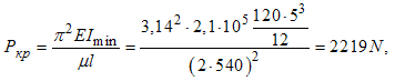 when
when  - factor in the reduced length of the spring, equal to 2 . l - spring length 540мм, selected constructively.Assume that after unloading platform which has reached the maximum angle of inclination 550, there was a need in the product repair and maintenance of mechanisms located on the trailer frame. In this case, the force is applied hydrolifts P, whose value can be determined depending on:
 It is evident that the safety factor is
  , that is enough.To lower the platform to the end of the ribbon spring load must be applied Рр, created by a mechanic from the mechanism control device when it is deformed. We also believe that the movement of the free end of the spring is 20mm, assuming that the diameter of the spherical projection on the spring is 18мм. We also believe that the material is spring steel 60С2А for ГОСТ 14959-79 a modulus of elasticity Е = 2,1·105 MPа and
  . We choose the safety factor nТ = 1,75 and then the amount allowable stress
  The numerical values of effort Рр depending on:
  It can be seen that this force is very significant in comparison with the permissible that a worker can attach to the control levers according to the ergonomic requirements for such control systems, and therefore the construction of the spring control mechanism must enter the tape transfer mechanism gear ratio is not less than U = 3,5. Then pull on the handle control mechanism of elastic deformation of the spring will not exceed 21kg. Such transmission mechanism may be configured, for example, as a two-armed lever pivotally supported on one arm of the trailer frame is pivotally attached to the handle 15 (see Figure 4) and power 100mm, and the other, designed to rotate it has the length 350 mm.To automate the settlement of the choice of material and geometrical characteristics of the support post for dump trailers and semitrailers of various models and capacity, developed a computer program in the language of Delphi, which was tested on the tractor and trailer, such as 2PTS-4-793-01, 2PTS -4-887, 2- PTS-4М , 3- PTS-12, and car trailer models GKB-819 and GKB -8527.Analysis of extensive literature and patent sources allowed to develop a promising technical solution to exclude injuries maintenance personnel engaged in the operation of tractor tipper trailers by using the automatic locking platform in position at its dump unloading. This design is recognized as the invention (RU2376162) and can be linked to not only two-axle tractor, but also road tipper trailers. Figure 5 shows a general view of the tipper-axle trailer, an enlarged view of the hydraulic ram, and a schematic diagram of an apparatus for fixing the inner tube hydraulic ram.Two-axle dump trailer consists of chassis 1 to diameters 2 of which with the fingers 3 hinged outer tube 4 hydraulic ram, and it posted its small movable pipe 5. Shallow tube 5 is pivotally connected to the platform 6. At the outer tube 4 are channels 7 movably arranged therein a spring-loaded compression springs 8, a ball shaped latches 9 interacting with the bottom 10 of small pipe 5.
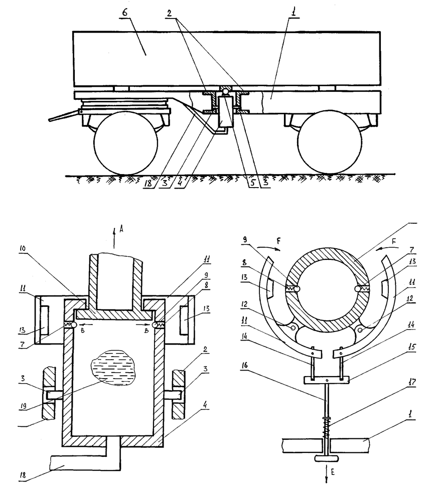 | Figure 5. Technical solution for patent RU2376162 |
The outer tube 4 is covered by the hydraulic ram 11 of the bell crank 12 by hinges mounted on the outer tube 4. One ends of two-armed levers 11 are provided with permanent magnets 13 and others, by means of rods 14, pivotally attached to crossmember 15 is rigidly fixed to the rod 16, mounted movably on the chassis 1 and a spring-loaded by a compression spring 17 with respect to the latter. The outer pipe 4 is connected to the hydraulic ram of the tractor hydraulic system (for it is not shown in the drawings) by a conduit 18, feed the hydraulic fluid 19 in the hydraulic ram. Powered Two-axle dump trailer follows. To unload cargo from the tipper platform 6, commonly known in the art, is fed under pressure from the hydraulic fluid 19 in the conduit 18, and under the action of a small pipe 5 extends from the outer tube 4 at the arrow A, and reaches a position as shown in Fig. 5. Before it reaches the position of the bottom 10 with their end surfaces interact with the ball shaped latches 9 retractable blocked by arrows B in the channels 7 formed in the outer tube 4, and when the bottom 10 to be held by the latter, under the action of compression springs 8 ball shaped latches 9 are returned to the initial position such as is also shown in fig.5. In case of leakage of the working fluid 19 or other emergency situations under the effect of its own weight of the platform 6 small tube 5 can not move downward in the direction opposite arrow A, since the ball shaped latches 9 securely fixed in its said upper position. In this position, the hydraulic ram service personnel without fear of Self-start platform 6, producing underneath repair or maintenance work. For lowering the platform 6 in the transport position to drawn 16 by the arrow E (Fig. 5) corresponding to the applied force and she moving in this direction, helps turn double-arm levers 11 of the arrows F, and once they have their permanent magnets 13 to touch the surface of the outer tube 4 by the magnetic force of attraction ball shaped clamps 9 move the arrows B, thus providing easy access to the bottom 10 of the small tube 5 between them. Thereafter, the force acting on the arrow E is removed, and under the action of compression spring 17, rod 16 returns to its original position, turning of the bell crank 11 in a direction opposite to arrows F. Further described processes may be repeated several times.Analyzing the structure of the above devices and his work can be seen that the most important parameter is the initial pair of radial forces applied Pr permanent magnets located on the bell crank operated by a thrust manually. The numerical value of each of these forces can be determined according to known: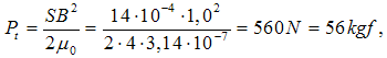 when В – magnetic induction, 0,5Т;
 μ0 – magnetic permeability of the gap,
 S1 – area of the contacting surfaces of the permanent magnet and a half spherical surface clamp diameter 30mm,
  If we consider that between the permanent magnet and ball retainer is a compression spring, then we will force its total deformation equal 25kgf and, using reference data [13] choose its rigidity equal с = 2,76 kgf/mm, such that the geometrical characteristics of the spring as follows: the total number of revolutions n = 5, the outer diameter of the spring DH = 24 mm, step loop t = 6 mm, spring material – wire Н by GOST 5047-79.For the economic evaluation, with the possible introduction of the proposed technical solutions used technique financial investment analysis and audit in the implementation of new technology [17]. As a basic sample accept serial Tractor tipper trailer model 2PTS-4-793A, which is mounted on the chassis frame hydrolift made on these RU2463179, RU2481971. According to existing regulations placed on the trailer overhaul after its run in 150 000 km and at this time it will be possible to retrofit. Calculation of economic efficiency of implementation of the proposed technical solutions, such as follows. For this we use the following parameters (see Table 1).
Тable 1. Input
 |
| |
|
1. Comparative economic efficiency ratio, defined according to: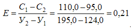 2. Bring cost ratio to the same production volume serial trailer will be: 3. These costs maps to the trailers:а) by serial –
  b) by modernized -
 4. These costs are subject to the same reduction factor production volume trailers:
 Based on the above calculation will produce the profits that the company will receive from the issuance of a modernized trailer considering the use of perspective in its design depending on the hydraulic ram:
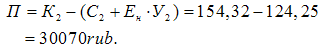 In conclusion, let us consider another solution, the design of which is the most simple in comparison with the above at the same time the body of the trailer is fixed in the raised position automatically, as it excludes the self-movement of the raised transport position if the working fluid in the hydraulic tipping trailer body or tractor receives exhaustion. This design is recognized as the invention (SU802103) and is shown in Figure 6.So in Figure 6 shows a safety fence with lowered body, the same process of unloading and dump it in the position of the body when unloaded.
 | Figure 6. Schematic diagram of the stop lock body tipper trailer |
Safety stop is located on the chassis 1 and of the tipper body 2. Chassis 1 hinged rod 3, the latter being inserted into the support 4 is rigidly connected to a stationary mechanical overboard 5 of the body 2. Inner surface of the support 4 is in the form sheeted hyperboloid. In the support 4 formed a transverse hole 6 in which is located a latch with a handle 7 of the stopper 8. Spring 9 biased latch 7. Between the chassis 1 and the body 2 installed cylinder 10.Work safety stop is as follows. When unloading dump body 2 is widely known in the art methods fed under pressure working fluid in the cylinder 10. When this occurs as lifting body 2 and its tilt toward the unloading of bulk cargo as it is shown in Figure 6. With this tilting of body 2 rod 3 moves relative to the support 4, the upper end of the rod 3 may be below the transverse hole 6 of the support 4. Covers the opening latch 7, the support 4 in any case retaining its fixing element relative to the body of support 4 or fixed support side of the end 5. Therefore after unloading, and return the body to its original position 2 does not occur locking rod 3. when setting the trailer repairs or maintenance of the tractor with the handle 8 release from locking latch 7, and the last part of the transverse hole 6 support 4. Then fed pressure cylinder 10 and the body 4 is moved upward in the direction indicated by the arrow in Figure 6, while the rod 3 is moved within the support 4, and when the upper end portion of the rod 3 passes transverse holes 6, the inner cavity of support 4 overlaps by latch 7 whereby lowering of body 2 excluded. Later the body 2 to return to its original transport position it somewhat lifted, output latch 7 by lever 8 compressing the spring 9 and lock lever 8 on the mechanical side 5. Further described processes can be repeated several times. Analyzing the proposed solution can be seen that the most crucial element of its design is the rod 3, which in the course of their work may become unstable under the action of load discharged from the body. Therefore, we perform stability analysis of such a structural element as follows assuming that the largest numerical value of the effort applied to the rod 1 (see Figure 6) will be equal to the then when the body reaches its maximum tilt angle and completely cleared of loose cargo while the pressure in the hydraulic cylinder and disappear rod accept the load from its own weight empty body. As input data, for example, for automotive tipper trailer 2PTS4-793А and determining Ркр and σкр we use the following parameters: net weight of the trailer body 620 kg, length of the rod l = 1200 mm, outer diameter of the rod D = 40 mm, inner diameter of the rod d = 30 mm, Steel rod material 65 by ГОСТ 14959 – 79, elastic modulus of the rod material Е = 2,0∙105 МPа, coefficient characterizing the mounting rod μ = 1.For this we use the well-known procedure [18] and define the following parameters:moment of inertia of circular cross-section of the rod: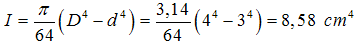 cross-sectional area of the rod:
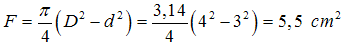 radius of inertia:
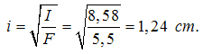 Establish the possibility of using Euler's formula by comparing the value of the flexibility of the rod ratio characterizing the use of Euler's formula:
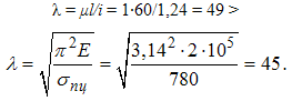 As 49 > 45, as to determine the critical force Ркр Euler's formula is acceptable, which can be calculated by following the provided dependency, and to determine the numerical value of the critical stress :
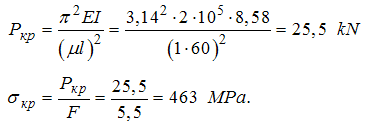 It is seen that the resulting value is less than the critical stress limit of proportionality for the above material from which the rod is made and power
  [19].
[19].
4. Results of the Study
Based on the foregoing, the following conclusions and suggestions:1. Analysis of both domestic and foreign automotive designs of dump trailers and semitrailers shows that the latter have a significant drawback, we conclude that in the maintenance of the latter, when the body is overturned in the absence of supports often is their self-starter and then the maintenance staff located in this zone, prone to injuries with severe outcome.2. Given the above as inventions (RU2463179, RU2481971, RU2314941, RU2376162 and SU802103) developed technical solutions enable automatic operation safety pillar reliably fix the latter in the tilted position , as it excludes the self-starter in the event of any failure in the hydraulic systems of tractors and trailers due to leaking liquid. Moreover the proposed technical solutions allow you to exclude injuries attendants generating repair and maintenance work while under the trailer raised his body. For example, the calculations as applied to automobiles tipper trailers 2PTS-4-793A , showed that applying a stopper ( biscuit ) in the design of hydraulic lifts performed Patent RU2463179, RU2481971 and made rectangular with dimensions (height h = 35,0 mm width b = 25,0 mm) and the applied load Q = 965 kg = 9650 N, acting on its own weight of the body, the cutoff voltage range from 135 MPa whereas their permissible value for the Steel 45, which is made of a stopper is 418 MPa. If locking the body to perform patent SU802103, then the calculation of the support leg for stability, in case it is used also in the design of Automobile and Tractor tipper trailer 2PTS-4-793A showed last made of a hollow rod of circular cross section, allows you to securely hold the body in an elevated position with loss its stability will occur at critical force Ркр equal to 25.5 kN, while the workload on the rod support post for this trailer is only 0,965 kN. 3. The calculations also showed that the introduction of the proposed design, for example, Patent RU2463179, RU2481971 increase operational safety trailers associated with reliable fixation of the trailer body in an inclined position is advantageous for production and operational structures of the national economy, as machine-building enterprise of the issue, for example, in the amount of 20.0 thousand units per year can make a profit of 1.2 million rubles per year at the rate of 30.07 thousand rubles. One trailer model 2PTS-4-793A. At the same operating conditions, work safety when servicing or repairing a trailer equipped with the above fixation device tilting hydraulic lift will be provided.4. Results of the study recommended the use of SRI industry automotive industry, agricultural machinery and engineering departments of enterprises commercially manufactured, repaired and operated automobile and tractor tipper trailers, both in our country and abroad. At the same time, all of the above developments transferred production structures involved in repair and modernization trailers Lipetsk region, and on the basis of agreements on creative collaboration with the latter, it is planned in 2015, the production of prototypes of the proposed technical solutions tied to tractor trailers, followed by manufacturing prototypes and test them in an operational environment.
References
| [1] | Glushchenko A.D., Slivinskii E.V. Dynamics and strength of the transport system for carrying light loads. Fan, Tashkent, 1988. 116c. |
| [2] | Vysotsky M. S., Dobras L.I., Sirotkin Z.L. Automobile and tractor trailers. M.: Mashgiz. 1962. 161 pages. |
| [3] | Osingurov V. V. Cars dump trucks. M.: Mashgiz, 1952. Page 124. |
| [4] | Markelov S. P., Krylov Yu. N. The modern constructions of automobile trailers of the capitalist countries. M.: Tsniiavtoprom, 1976. - 118с. |
| [5] | Velikanov D.P. Development of road trains and their dynamic qualities//Automotive industry, 1960, No. 2. Page 22. |
| [6] | Dmitrichenko S. S. Research of fatigue resistance of tractor trailers//Tractors and agricultural machines. 1986. No. 6. Page 16 — 17. |
| [7] | Zakin Ya. X. Application-oriented theory of movement of the road train. M.: Transport, 1987. Page 286. |
| [8] | Bakhmutsky M. M., Sharapov V. K. Researches the course stability of the road train with the trailer having the turning device of automobile type//Automotive industry. 1969. No. 7. Page 26. 15. |
| [9] | Nazarenko A. G. Dinamika of the tractor train and technique and equipment development for test of autotractor trains for oscillations//Avtoref. yew. Dr. tech. sciences. Novosibirsk, 1963. 46 pages. |
| [10] | Schukin M. M. Coupling devices of cars and tractors. M — L.: Mashgiz, 1961. 206 pages. |
| [11] | Dmitrichenko S. S. About a resource of operability of frames tractor trailers and other machines//Welding production. 1968. No. 10. Page 22 — 23. |
| [12] | Proskuryakov V. B. Dinamika and durability of frames and casing of transport machines. L.: Mechanical engineering, 1972. 229 pages. |
| [13] | Slivinsky E. V. Improving of utilization properties of hook-on vehicles on the basis of effective scientific and technical solutions. Avtoref. yew. doctors техн. sciences. Eagle: GTU, 2010. 334 pages. |
| [14] | The reference manual on transport maintenance in agriculture. M.: Rosselkhozizdat, 1975. - 400с. |
| [15] | Bases of the theory and calculation of agricultural machines on durability and reliability. Under the editorship of P. M. Volkov. M.: Mechanical engineering, 1977. - 310с. |
| [16] | P. I. Orlov Of a basis of constructioning. In 2 N. of Book 2. No. - е prod. исправл. - M.: Mechanical engineering, 1988. - 544с. |
| [17] | Gilyarovskaya L.T. Endovitsky D. A. financial and investment analysis and audit of the commercial organizations. – Voronezh: Publishing house of the Voronezh state university, 1997. – 336с. |
| [18] | Feodosyev V. I. Soprotivleniye of materials. – M.: Science, 1970. 544с. |
| [19] | All-technical reference / E.A. Fast walkers, V.P. Zakonnikov, A.B. Paknis, etc. Under the editorship of E.A. Skorokhodov. - 4 prod. испр. – M.: Mechanical engineering, 1990. 496с. |
 Abstract
 Reference
 Full-Text PDF
 Full-text HTML