Oleksandr Mokin, Borys Mokin, Yuriy Lobatiuk
Department of Renewable Energy and Transport Electrical Systems and Complexes, Vinnytsia National Technical University, Vinnytsia, 21021, Ukraine
Correspondence to: Yuriy Lobatiuk, Department of Renewable Energy and Transport Electrical Systems and Complexes, Vinnytsia National Technical University, Vinnytsia, 21021, Ukraine.
| Email: |  |
Copyright © 2014 Scientific & Academic Publishing. All Rights Reserved.
Abstract
The paper presents simulation model for the monitoring of the train line of the train air brake system by which the search of the breakage of this train line could be easily automated. There had been designed block diagram of the simulation model and it’s realization by MATLAB Simulink.
Keywords:
the Simulation Model, the Train, the Air Brake, the Train Line, the Point of Breakage
Cite this paper: Oleksandr Mokin, Borys Mokin, Yuriy Lobatiuk, Simulation Model for the Monitoring System of Air Brake of the Train and Determining the Place of Breakage, International Journal of Traffic and Transportation Engineering, Vol. 3 No. 4, 2014, pp. 184-188. doi: 10.5923/j.ijtte.20140304.02.
1. Introduction
During the process of electric train motion in intermediate connections under the influence of vibrations (and also under additional rail deflections at curves and air masses vortices that can be saturated with solid particles taken by vortices from gauge line surface) breaks may emerge across which the leakage of compressed air from train line and pressure loss can occur. It should be noted that one of the main types of train brakes is the brake system with automatic indirect brake, characteristic feature of which, as shown in [1], is that they are triggered automatically without the driver in any decrease of pressure in the train line – whether it occurs activating train emergency brake, the train line breakage or separation of intermediate joints.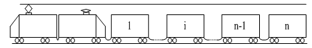 | Figure 1. Simplified functional diagram of electric train |
After breakage of the train line the train must stop (before reaching the station) and mechanic visually or aurally has to identify the location of the breakage. This procedure disrupts the schedule of all trains on this section of the railway. So it’s very important task to quickly find a place of breakage of train line. That’s why this paper presents creation of measuring system for monitoring of air brake train line and determining the distance to the place of breakage.In paper [2] had been suggested to solve the problem of automatic finding place of breakage in the air brake line of the train using a mathematical model.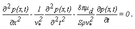 | (1) |
that describes the process of change of pressure  along the train line with a cross-section S and with an open end of the train line on the coordinate x and time t in the absence of intermediate air leaks through its wall, where
  – the speed of the sound in compressed air of the train line,
  – the density,
  – dynamic coefficient of viscosity of the compressed air (figure 2).
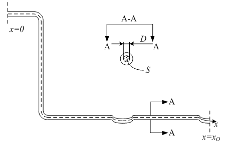 | Figure 2. Simplified functional diagram of the section of air brake system of electric train from the locomotive to the breakage |
Solving this equation we have obtained the formula for determining the coordinates of the point of breakage or crack of the train line which counting from the electric locomotive’s dashboard | (2) |
where  could be calculated from
 | (3) |
which for time  when there is the breakage of the train line
 | (4) |
and on the basis of which for the two moments of time  advancing after the time of the breakage of train line we can write an equation
 | (5) |
Expressions (2), (3), (4), (5) are initial conditions for us to solve the problem of creating a simulation model for the monitoring of the train line of the air brake system of the train whereby easily could be automated the search of the breakage of the train line.However, taking into account the mathematical model described by expression (1) let us focusing on the conditions under which this model can be used. Namely – the absence of air leakage through the walls and inflow of compressed air into the train line. Therefore it is necessary to pay special attention to the processes occurring with air brake system of the train during movement under different conditions and to the appropriate actions of locomotive driver.To do this, let’s briefly review some of the basic design elements of the train air brake system and the features of its work.Basic actions to manage the air brake system are performed using a control valve CV (see figure 3). It has seven fixed positions of the handle: I – compression, charging; II – moving; III – shutdown without feeding; IV – shutdown with feeding; Va – slow decompression; V – full service braking; VI – emergency braking [4]. | Figure 3. Schematic diagram of the train air brake |
The system also includes the air distributor and reserve tank RT. Air distributor consists of the piston and the spool valve and works on the principle of differential pressure. Setting driver’s crane in Va, V or VI position the driver connects the brake line 2 to the atmosphere. Brake pressure begins to decrease and the piston of the air distributor begins to move to the left side because from the right side it is acted upon pressure from the storage tank. After moving to the left position the spool valve gives the way for compressed air from the reserve tank RT to fill the brake cylinder 3 and thus increase pressure in it. As a result, the plunger of the brake cylinder 3 through linkage presses the brake lining to the wheel.For brake release driver sets the handle in I position. This leads to that the pressure of the supply line 1 is going to the brake line 2. Then the spool valve of the air distributor moves toward the right, thereby connecting the cavity of the brake cylinder with the atmosphere and unblocking the wheel. The last action also leads to the replenishment of the reserve tank by required pressure.It is not always necessary that the brake is fully triggered or released. So driver partially replenishes or relieves pressure of the brake line. To fix the particular effort of the brakes III and IV position of the crane driver are used. In the IV position (shutdown with feeding) all unauthorized leakage of air from the brake line are replenished.During the movement of the train the handle of the driver’s crane is in the II (moving) or IV (shutdown with feeding) position. Under these conditions the brake line is in the charged state and unauthorized air leakage are compensated from main reservoirs for preventing pressure reduction and unauthorized braking of the train.The feature of the train air brake system is that at pressure decrease in brake line to 0.2 bar compressor switches on and at the same time the alarm in the driver’s cab with indicator light «Breakage of the train line» turns on.Thus, when there is an emergency the air pressure in the supply line lost as a result of breaking the brake line but through a short period of time it will begin to recover by the pressure of air coming from the main tanks. And for replenishment of the main tanks with compressed air the compressor starts to work constantly what could be an additional sign of an emergency.It should be noted that in the case of train line breakage the air volume in the main tank (200 liters under a pressure of 9 bar) and the compressors will be able to maintain the air brake system in a charged state. However, it is clear that the braking system in train cars beyond the break point will be discharged and the brake linkage as a result of the discharge will be in a locked state leading to emergency braking or separation from those cars that are beyond the point of breakage.
2. Main Results
To construct the block diagram of the simulation model based on expressions (2), (3), (4), (5) first need to find the value of fixed time  (explicitly). For this we use the expression (5), from which
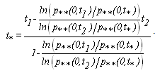 | (6) |
Next, let’s pay attention to the fact that, as shown in [2], parameter  is equal to the pressure in the train line of the air brake system before the breakage (so it equals to normative pressure for this braking system and at the same time also acts as a parameter
  ) and parameter
  is equal to the pressure in the train line in the point of breakage, i.e. is equal to atmospheric and simultaneously acts as a parameter
  .Based on the expressions (2), (3), (4), (6) and on the above remarks (concerning the pressure in the beginning of the brake line before the breakage and the pressure in the point of breakage at this line) the block diagram of mathematical model for determining the point of breakage of the train line of the air brake system will have the form shown in Fig. 4.
 | Figure 4. Block diagram of the mathematic model for the breakage point determination of the train line of the air brake system |
Therefore, to provide the conditions under which the mathematical model (1) could be applied as well as correctness of the algorithm of the diagnosing based on this model we have to select the moments of time  and
and  when pressure has already begun to decline but the compressor that fills the main air reservoirs hasn’t enabled yet. Pressure values
  ,
,  are the respective intermediate pressure values taken from the curve of its decrease in case of the breakage of the train line. As a software environment for simulation modeling of the train line of the air brake system of the train let’s use computing environment MATLAB Simulink [3].Fig. 5 shows a screenshot of the simulation model.
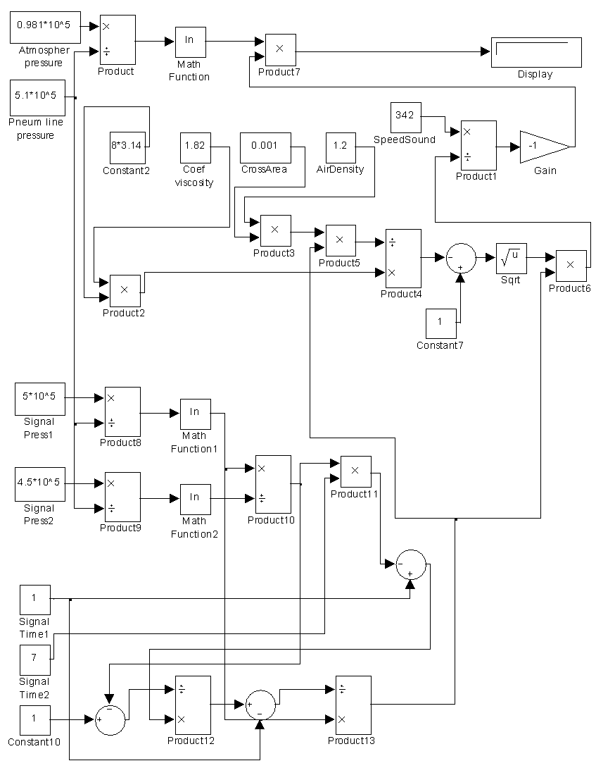 | Figure 5. Block diagram of the simulation model in MATLAB Simulink |
The names of the blocks on Fig. 5 and their meanings: «Pnev mag pressure» – the pressure in the intact train line; «Signal Pres 1», «Signal Pres 2» and «Signal Time 1», «Signal Time 2» – the values of pressure and time from the curve of dependence between pressure and time. Blocks «Coef viscosity», «CrossArea», «AirDensity» and «Speed Sound» contain values of the coefficient of viscosity, cross-sectional area of the pipe of the train line and the speed of the sound correspondingly. The value of the coordinates of the point of breakage of the train line displayed on the unit display information «Display».
3. Conclusions
Based on general mathematical model describing change of pressure in the train line of the air brake system of the train there had been created the detailed mathematical model appropriate for determining the point of breakage of the train line as well as the block diagram for the simulation modeling.There had been analyzed the principles of operation of the air brake system, determined conditions and suggested solutions that allow the control system to work correctly.On the basis of a detailed mathematical model using MATLAB Simulink there had been designed the simulation model appropriate for determining the place of breakage of the train line of the air brake system and for developing a device that will be installed in the driver’s cab for providing automatic process of determining the point of breakage.
References
| [1] | V. I. Krylov, V. V. Krylov “Automatic Brake of Rolling Stock”, M.: Transport, 1983, 360 p. |
| [2] | O. B. Mokin, B. I. Mokin, Y. A. Lobatiuk, V. A. Lobatiuk. “Synthesis of Mathematical Model for Diagnostics of Pneumatic Brake System of Electric Train”, Scientific Works of Vinnytsia National Technical University, 2013, № 1. |
| [3] | Yu. Lazarev “Modeling of processes and systems in MATLAB. Training course”, Saint Petersburg: Peter; Kiev: Publishing Group BHV, 2005, 51 p. |
| [4] | E. I. Galay, E.E. Galay “Braking systems of railway transport. Structure of braking equipment: study guide”, Belarusian State University of Transport, Gomel, BelSUT, 2010. |
 Abstract
 Reference
 Full-Text PDF
 Full-text HTML