-
Paper Information
- Paper Submission
-
Journal Information
- About This Journal
- Editorial Board
- Current Issue
- Archive
- Author Guidelines
- Contact Us
International Journal of Traffic and Transportation Engineering
p-ISSN: 2325-0062 e-ISSN: 2325-0070
2014; 3(3): 162-174
doi:10.5923/j.ijtte.20140303.03
To Increase of Efficiency of Use of Heavy-Load Road Trains at the Expense of Increase in Their Tonnage
 Abstract
 Reference
 Full-Text PDF
 Full-text HTML
Slivinsky E. V., Korchagin V. A., Radin S. Yu., Rizayeva Yu. N.
Yelets state university of I.A. Bunin, Lipetsk state technical university
Correspondence to: Slivinsky E. V., Yelets state university of I.A. Bunin, Lipetsk state technical university.
| Email: |  |
Copyright © 2014 Scientific & Academic Publishing. All Rights Reserved.
In the present article the materials concerning development of perspective constructions of devices intended for heavy-load road trains, allowing to increase their tonnage due to reduction of space located between edge part of a cabin of the car of the tractor and answer part of a body of the semi-trailer are provided. As a result of research and analysis of existing designs used in the international community, developed at a number of inventions complex technical solutions to train in motion the rest automatically change the specified space. Created design schemes such devices and techniques used to study the proposed force loading of structural elements that allow for studies to assess the effectiveness of the use of the proposed structures and calculated on the basis of their basic rational geometrical parameters of their components. Results of research it is recommended both domestic, and to foreign research and development and industrial structures in the field of automotive industry for the purpose of its further study and possible implementation in practice.
Keywords: Constructive gap, Frame, Kingpin, Module, Pneumatic cylinder, Saddle device, Semi-trailer, Tonnage, Toothed sector, Tractor
Cite this paper: Slivinsky E. V., Korchagin V. A., Radin S. Yu., Rizayeva Yu. N., To Increase of Efficiency of Use of Heavy-Load Road Trains at the Expense of Increase in Their Tonnage, International Journal of Traffic and Transportation Engineering, Vol. 3 No. 3, 2014, pp. 162-174. doi: 10.5923/j.ijtte.20140303.03.
1. Introduction
- Now, in the conditions of market economy, special requirements are imposed to railway, sea, river and to other means of transport which will form single transport system as in our country, and abroad. The motor transport is an essential component of this system. Development of the motor transport in Russia is inseparably linked with creation of domestic automotive industry which achieved today certain success as in qualitative, and in a quantitative sense. It is known [1-3] that an automobile rolling stock separate on cargo, passenger and special, and the first is used in transit the wide nomenclature of loads on the different distances reaching one thousand kilometers and more. The special place in this type of a rolling stock is taken by the heavy-load road trains consisting of cars tractors with power up to 300 kW and above and semi-trailers with a loading capacity of 24000 kg and more. Despite the efficiency of use last possess a row of constructive shortcomings which significantly affect their productivity, the contents, safety in maintenance and repair. Automobile trains (fig. 1), unlike single cars, are the spline rolling stock possessing high performance, rather simple construction, good maneuverability, etc. Kinematic and force interaction of links of road trains and transmission of a towing capacity to semi-trailers is carried out via the reference coupling devices which details are mounted both on the car the tractor, and on the semi-trailer [4-18]. Reference coupling devices are applied to transportation of semi-trailers and are constructions which perceive not only longitudinal loadings, but also vertical from a curb weight of semi-trailers, executing at the same time functions of the turning mechanism [18-26]. The following main requirements are imposed to reference coupling devices: simplicity of construction; small curb weight; the relative low cost; reliability of action; support of necessary flexibility between interfaced links of the road train; possibility of a fast and safe hitch and declutching of links; damping of dynamic loads in case of road train movement, etc.
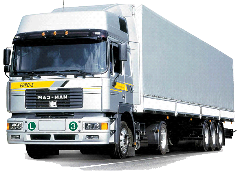 | Figure 1. General view of the heavy-load road train |
2. Research Objective
- Based on the above, an objective of this research is:1. Development of the technical solutions allowing in an automatic mode, in case of angular turns of the tractor and the semi-trailer to regulate a gap between its cabin and the semi-trailer and by that to increase tonnage of the semi-trailer due to use of "dead space".2. Development of estimated diagrams and carrying out test calculations on durability of responsible nodes of the perspective saddle devices providing an automatic mode of regulation of a gap between a cabin of the tractor and the semi-trailer.3. Development of perspective constructions on further enhancement of element basis of heavy-load road trains.4. Use of a program complex for the computer, allowing to determine rational parameters of the devices, allowing to regulate in an automatic mode a gap between a cabin of the tractor and a semi-trailer body.
3. Research Technique
- We will consider the first technical solution which is recognized by the invention (RU2214338).In fig. 2 the general view of the road train, and a row of sections of its saddle device is shown. Operation of such road train happens as follows. In case of rectilinear movement when the gap "δ" is minimum, toothed rails 9 are rested against delimiters 11 of a frame of the 7th car tractor 1 under the influence of springs сжатия10, and kingpin13 and a finger 16 lie on one axis in the longitudinal plane of the road train. In case of road train turn the semi-trailer 12 is turned on a saddle 3 reference coupling devices 2 but as the finger 16 enters a notch of a saddle 3, it on an arrow N turns the reference coupling device 2, and, therefore, and the additional casing 4 in the same direction in the guides 6. But the additional casing 4 is rigidly connected to toothed sectors 8, therefore, and they make similar angular turn also on the arrow N.B the queue, at the expense of a linkage of sectors 8 with rails 9, there is the linear relocation of the right toothed rail 9 on an arrow M, realizing compression of its spring 10, thus the left toothed rail 9 doesn't move as it is rested by the end against the delimiter 11 of a frame of the 7 tractor 1.
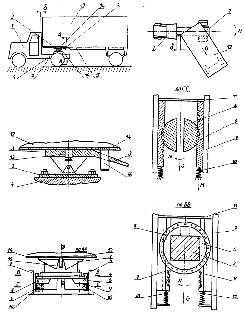 | Figure 2. Construction of the saddle device according to the patent RU2214338 |
 = 18300 kg;4. Vertical load attached to the saddle device – 74600 N;5. Dynamic coefficient КД when braking in a hitch – 1,91;6. Coefficient of rolling resistance (road train movement in the conditions of bad quality of a paving, a hollow, the snow road, etc.) f0 = 0,05;7. Diameter of an initial circle of toothed sectors d0 = 640 mm.
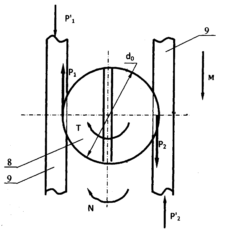 | Figure 3. Estimated diagram |
 and then
  We will select a material for toothed sectors and rails. As the kinematic couple open also is spur gear, we accept for sectors the Steel 45 improved to average hardness of HB 280 (σВ = 730 MPa and σТ = 390 MPa and diameter of preparation to 900mm) and the same steel with the same parameters for toothed rails. We will determine allowable stresses of a bend of teeth in case of an endurance limit in case of basic number of cycles 107 by dependence [11].σ0F1 lim b=1,8 НВ=1,8·280=504 MPa.Coefficients of longevity of KHL for toothed rails and toothed sectors we accept KHL= 1, and safety coefficients for them we set SF = 1,1. Then the allowed contact tension
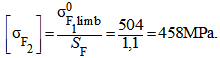 We will approximately read that on diameter of d0 65 teeth will be located. Then for such number of teeth of Z2 (for toothed sectors) the coefficient of the form of teeth will be equal to yF2 = 3,62, and for teeth of rails in case of Z1=∞ yF1=3,54. We will select coefficient of width of a wreath of toothed sectors ψbd recognizing that their layout concerning the casing of the saddle device is the symmetric ψbd = 0,4. Also we will set coefficient of non-uniformity of loading of KF from recommendations of operation of [11] equal KF = 1,20. The selected values allow to calculate the linkage module on known dependence:
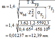 We accept the module in accordance with GOST 9563-60, m = 12 mm. Proceeding from a certain module, we will determine number of teeths of toothed sectors:
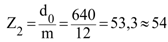 Diameter of overhangs of sectors will be:
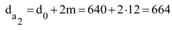 We will determine tension of a bend arising in the base of tooth:
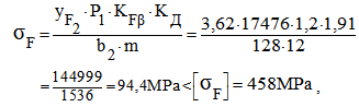 where: b2 – width of a wreath of a toothed sector
 The condition of durability is satisfied and, apparently, its inventory is considerable. We will define a step of a toothed linkage
 Now we will define value of a course of "H" of the semi-trailer concerning the car tractor in case of its angular turn, thus reading that ¼ part of teeth of sectors participates in it, therefore, in case of turn on an angle 900 to a rail contacts
  teeth.Then:
  The calculations carried out thus show that:1. In case of d0=700mm,
  teeth; H=14,5·37,68=546mm.2. In case of d0=800mm,
  teeth; H=16,6·37,68=628mm.3. In case of d0=900mm,
  teeth; H=19,0·37,68=706mm.4. In case of d0=1000mm,
  teeth; H=21·37,68=791mm.5. In case of d0=1200mm,
 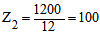 teeth; H=25·37,68=942mm. As width of frames of saddle cars tractors is various and lies ranging from 490 mm to 1200 mm, numerical values "H" of a course of semi-trailers can be received, setting on them toothed sectors with d0 equal from 500mm to 1000mm and more on such truck tractors as: ZIL-131V, Urals-377СН, KAMAZ-5410, KAMAZ-54112, MAZ-5432, and also foreign Skoda-706RTTN models, Mercedes Benz 2232S, Volvo-F89-32, etc. Based on the above we will make calculation of internal volumes of bodies of different semi-trailers reading that in case of installation of a toothed sector in the saddle device of the car of the tractor with d0 = 1000 mm, last can in case of an initial gap between a tractor and semi-trailer cabin of equal 150 mm to move when maneuvering road train on value 791-150 = 641mm (where 791 mm are selected from a row of H received above). We will make such calculations for different models of the serial semi-trailers having the following internal dimensions of bodies:1. ODAZ-794; 6660×2370×1850mm with V1 = 29,2 m3 2. ODAZ-795; 9110×2370×1850mm with V2 = 39,9 m33. ODAZ-935; 9110×2370×1850mm with V3 = 39,9 m34. ODAZ-857B; 8615×2350×1830mm with V4 = 37,0 m35. N12ALKA Semi-trailer; 7370×2060×1840 mm with V5 = 27,9 m36. SAVUAYaRD Semi-trailer; 12000×2430×2300 mm with V6 = 67,0 m37. IWT Semi-trailer; 12150×2430×2340 mm with V7 = 69,0 m3Then at the upgraded road train internal volumes of bodies of semi-trailers will be defined:1. ODAZ-794; (6660+641) × 2370×1850 with V1 = 32 m32. ODAZ-795; (9110+641) × 2370×1850 with V2 = 42,76m33. ODAZ-935; (9110+641) × 2370×1850 with V3 = 42,76m3 4. ODAZ-857B; (8615+641) × 2350×1830 with V4 = 39,8m35. N12ALKA; (7370+641) × 2060×1840 with V5 = 30,36m36. SAVUAYaRD; (12000+641) × 2430×2300 with V6 = 70,7 m37. IWT; (12150+641) × 2430× 2340 with V7 = 72,7 m3Analyzing the received values of internal volumes of bodies it is visible that they increased ranging from 2,86 to 3,7м3, that is tonnage of semi-trailers on the average increased by 5,4% ÷ 9,6%.Considering variety of constructions of the road trains used in our country, for calculation automation in each case of the parameters characterizing construction of the saddle device to them, in the Delphi language the ZIL133V1 of Odaz-395 program in which, varying basic data such as – the semi-trailer loading capacity, its own mass, a vertical load on the saddle device, dynamics coefficient in a place of tractive connection, etc. was developed, it is possible to calculate the necessary module of a linkage and value of a course in case of progressive relocation of the semi-trailer concerning the tractor.Together with the previous sentence, other option of increase of tonnage of heavy-load road trains which is also recognized by the invention (RU2248903) is developed also. Such heavy-load road train and its appropriate sections is shown in fig. 4. It consists of the car of the tractor 4 supplied with the reference coupling device, executed in the form of the support plate 1 supplied with reference rollers 2, 3 frames of the tractor 4 contacting to longerons. The support plate 1 is supplied with the casing of a hydraulic cylinder 5 which is movably placed on the fixed piston 6 supplied with a rod 7, rigidly fixed by the two ends to cross-pieces of the 8th frame of the car – the tractor 4. On the support plate 1 brackets 9 with the fingers 10 swing joint connected to brackets of the 11th saddle 12 are set. On a saddle 12 the hydrodistributor 13 connected by the shaft of 14 to edge part 15, executed in the form of a truncated hexagon pyramid, kingpin 16, rigidly to the associated to reference sheet 17 of a frame the 18th semi-trailer 19 is fixed. Kingpin 16 it is recorded by the lock 20 put on a saddle 12. The hydrodistributor 13 is connected by the forcing pipeline 2 to the pump 22 and the drain pipeline 23 with a capacity of 24 which are set on the car – the tractor 4. By means of pipelines 25 and 26 the hydrodistributor 13 is connected to the casing of a hydraulic cylinder 5.The road train reference coupling device as follows works. In case of rectilinear movement of the road train shown, between the car – the tractor 4 and an edge wall of the semi-trailer 19 set a necessary gap δ and the casing of a hydraulic cylinder 5 is, for example, in extreme right situation. As soon as the car – the tractor 4 will start entering a curve of a road way, the saddle 12 will receive angular turn in the horizontal plane of rather reference sheet 17 of a frame of the 18th semi-trailer 19 and as kingpin by the 16th end executed, for example, in the form of a truncated hexagon pyramid, the 14th hydrodistributor 13, last is rigidly connected to shaft that is well known in technique, will connect the forcing pipeline 21 of the pump 22 to the pipeline 25, and working pressurized fluid on an arrow C will arrive in the right cavity of the casing of a hydraulic cylinder 5. As the piston 6 and its rod 7 are fixed, the casing of a hydraulic cylinder 5 will start moving on an arrow D, pushing out working liquid on an arrow E in the drain pipeline 23 and, therefore, in capacity 24. At the same time, due to tight coupling of the casing of a hydraulic cylinder 5 with the support plate 1, on the reference rollers 2 support plate 1 together with a saddle 12 will receive relocation on the same arrow D. And as in a saddle 12 it is placed kingpin 16, recorded concerning a saddle by the 12th lock 20 (such connection is widely known in practice of car connection – the tractor and the semi-trailer), in the same direction the semi-trailer 19 will move also. such movement of the semi-trailer 19 will allow to increase a gap δ between a car cabin – the tractor 4 and edge part of the semi-trailer 19, providing turn last, without touching a car cabin – the tractor 4. The car output – the tractor from a curve of a way is accompanied by turn of its saddle 12 in the side opposite to the above, and in this case the hydrodistributor 13 connects the pipeline 26 to the pipeline 21, and the pipeline 25 with the drain pipeline 23. Then working liquid arrives in the casing of a hydraulic cylinder 5 in the direction opposite to an arrow D, and working liquid will be pushed out on an arrow G in the pipeline 25 and via the hydrodistributor 13 will arrive in capacity 24 via the drain pipeline 23. such movement of the casing of a hydraulic cylinder 5 will allow just as it is described above, will move to the semi-trailer 19 aside, opposite to an arrow D which will reach home position with a gap δ between its edge part a car cabin – the tractor 4. Angular turn of the car – the tractor 4 to the opposite side also as well as in the previous case will provide semi-trailer 19 progress in the direction of an arrow D and the subsequent return his ambassador of an output of the road train from a way curve.
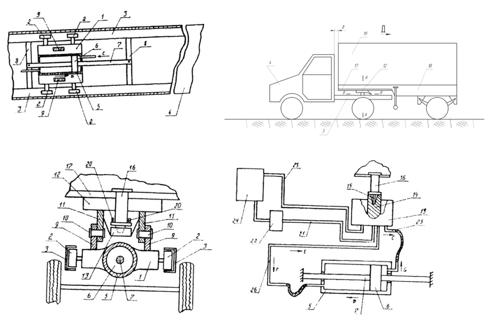 | Figure 4. Construction of the saddle device according to the patent RU2248903 |
 | Figure 5. Estimated diagram |
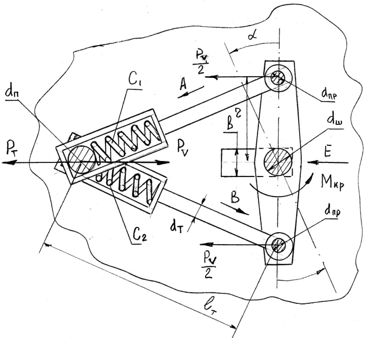
 in case of angular turn of the car – the tractor, the first case is characterized by origin of force of РТР, characterizing the moment of start-off of the road train from a place taking into account its input in a curve of a way, the second case, appearance of force of РТ arising in case of braking of the road train, as way entering a curve, and the third case
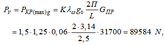
  piston loading by РV force in case of an input in a way curve in case of uniform motion of the road train with VA speed. It is clear that each of specified forces will have different value and therefore it is necessary to calculate such force which most characterizes a condition road train movement. The pilot studies [2, 4, 26] carried out with different on construction by domestic automobile road trains show that the loadings arising in the reference coupling device directly are connected to longitudinal oscillations of the semi-trailer excited by road roughnesses. It is known also that such loadings don't exceed loadings arising when braking the road train and its start-off from a place. In the same operation it is marked that the greatest loadings are characteristic for a start-off mode from a place and if to take them for 100%, loading in case of movement on the bumpy road averages from the above about 34%, and when braking 47%. Considering such nature of distribution, we will use the known formula [25], allowing to calculate such effort in case of road train movement on the uneven road for severe conditions of operation in case of roughness height of 2q0=12cm with wavelength of L = 2,5m, consisting, for example, from the car – the MAZ 6422 tractor and the semi-trailer – the ChMZAP container carrier – 9991 on dependence:
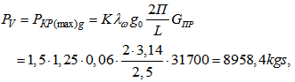 where:
  limit of coefficient of dynamism in case of radial oscillations of a place tractive connection, depending on aperiodicity coefficient γ, which can be accepted equal 0,4;К – the additional coefficient of dynamism considering influence of gaps in fifth wheel coupling device also is accepted equal 1,25;
 full the weight of the semi-trailer is 31,7 t.Considering the above it is visible that in case of start-off from a place the effort with in fifth wheel coupling device will make 268740 N, and when braking РТ = 126310 N. From the received computation it is visible that the greatest value is the effort of РТР = 26,9 hardware, however, its direction, in case of start-off from a place occurs on an arrow C (see fig. 5) and therefore pressure of the РА working liquid arriving in a cavity A a hydraulic cylinder on an arrow N can be small and the
  piston under the influence of РТР will force out last on an arrow M. Therefore the semi-trailer will move as on an arrow C, excepting a contacting of its edge part with a car cabin – the tractor. And here under the influence of effort of РТ arising in case of braking of the road train when the semi-trailer will "be rolled" on the car – the tractor, last it will be directed on an arrow D and its maximum value can make 12,6 hardware. In this case, to provide hydraulic cylinder movement together with the support plate on an arrow C in case of car turn – the tractor РА pressure and consequently also the effort on the piston in this direction shall be big than РТ= 12,6 hardware approximately by 1,2 times. We will make calculation of such effort of F in case of excessive pressure in a car hydraulic system – the MAZ 6422 tractor equal РА=10,0 of MPa. We will assign it is constructive diameter of the piston
  = 160 mm, and diameter of rods of
  = 80 mm and then in case of such sizes effort of F will be determined by dependence:
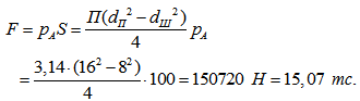 It is visible that the received value F meets the requirement
  and, therefore, the semi-trailer under the influence of created effort of a hydraulic cylinder of F = 15,07 hardware in case of car turn – the tractor will move on an arrow C, excepting a contacting of its end face with a cabin of the last.It is known that in maintenance there is the significant amount of different models of truck tractors, such as GAS – 52 – 06, ZIL – 130B - 1 – 76, ZIL – 131B, KAZ – 608B, the Urals 375CH, KAMAZ – 5410, KAMAZ – 54112, MAZ – 504B, KRAZ – 258B1 and so on, the ODAZ models exploited with automobile semi-trailers – 885, KAZ – 717, ODAZ – 9370, MAZ – 5205A, MAZ – 9398, MAZ – 9397 and a great number of others, and both tractors, and semi-trailers have different mass characteristics and the geometrical sizes. So, for example, the loading capacity of semi-trailers lies ranging from 7500 kg to 32400 kg, and their internal volume from 15 m3 to 70 m3 and more. Therefore in each case it is necessary to carry out a series of calculations for the purpose of establishment of the geometrical sizes of hydraulic cylinders used in fifth wheel coupling device of tractors. Considering it, the computer program in the Delphi language, allowing to solve objectives is developed. In application the program window by means of which, depending on brake forces, for the different road trains operating on the casing of a hydraulic cylinder, its geometrical parameters are calculated is shown. As a result of the carried-out calculations it is set that for the majority of cars – the tractors which are a part of road trains which trailers have loading capacity from 7,5 t to 15,0 t diameter of the piston of a hydraulic cylinder
  = 140 mm, and for loading capacity from above 15,0т shall be equal to
  = 165 mm.The simplest and most effective work in our opinion is the design, made by patent RU2240944, which describes a train (Fig. 6), consisting of a towing vehicle equipped with a fifth wheel coupling.
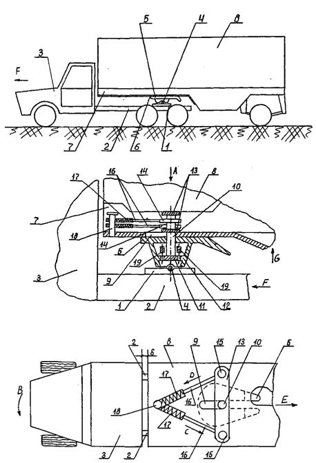 | Figure 6. Construction of the saddle device according to the patent RU2240944 |
 | Figure 7. Estimated diagram |
 where:
  limit of coefficient of dynamism in case of radial oscillations of a place tractive connection, depending on aperiodicity coefficient γ, which can be accepted equal 0,4;К – the additional coefficient of dynamism considering influence of gaps in the reference coupling device also is accepted equal 1,25;
 – gross weight of the semi-trailer with a load 31,7т.Therefore, in case of road train movement the vector of action of such effort will be directed back, i.e. towards the semi-trailer and therefore each of pull of the device are loaded with effort in 8958,4/2 = 4,48 kN, and in case of lever turn on an angle α one pull will be subject such loading to compression operating on an arrow A and its compression spring of C1 will be elastic to be deformed in the same direction, and other pull moving on an arrow B, stretching. And therefore the semi-trailer will move also back, excepting acontacting of its edge part with a car tractor cabin.Let's say that pull are executed from St 3 and their diameter of dТ = 50 mm. Then compression stretching tension in them will make σР(С) = 4·4480/3,14 · 5,02 = 22,8 MPa<[σ] = 160 MPa. The condition of durability is satisfied. In too time in case of angular turn of the double-arm lever the finger will work with diameter of dП for a bend. It is constructive we will assign
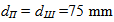 (according to the SAE standard diameter kingpin for automobile semi-trailers is equal 75mm). Then tension of a bend of a finger in this case will be equal
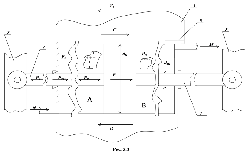
  = 4480·10,0/0,1·7,53 = 106,2МPa < [σ] = 120МPа, where 10,0 cm working length of a finger. The condition of durability is also satisfied. Now we will make calculation of durability of a serrated connection a car tractor kingpin-saddle, reading that the torsional moment on the kingpinin case of turn of the car tractor will make МКР= 4480 · 0,8 = 3584 kgs·m, where 0,8 radius of r of the lever of the device (fig. 7). We will check on durability a slit toothed linkage of an evolvent profile a kingpin-saddle. As kinematic couple the kingpin-sleeve open we will assign a splined joint accepting for it the Steel 45 improved to average hardness of HB 280 (σВ = 730 MPa and σТ = 390 MPa, and diameter of preparation to 250 mm). According to GOST 1139-80 we will select a heavy series with a diameter of overhangs it on the kingpin D = 160 mm and quantity of slits of z = 16. Length of slits (teeth of an evolvent profile) we will assign equal l = 100 mm. It is known that test calculation of such splined joints carry out on tension of a crushing on dependence [11, 12]:
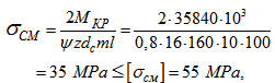 where, ψ – coefficient considering non-uniformity of load distribution between teeth equal 0,8;dс – diameter of a dividing circle is 160 mm;m – module of a linkage of 10 mm.It is visible that the condition of durability is satisfied.We will set geometrical characteristics of compression springs it is constructive recognizing that return to rectilinear position of the semi-trailer after an output from a curve of a way comes in road train movement. In this case pull which moved on an arrow A, will receive relocation in the direction opposite to it i.e. will work for stretching, and the spring of other pull will provide the smooth movement it without manifestation of a shock load in case of lever turn. Therefore according to recommendations of operation of [6, 11] compression springs will have the following parameters: outside diameter of a spring of DНАР = 80 mm, diameter of a round of d = 11 mm, operational load of
  = 3700 N rigidness of a spring of С1 = С2= 4,89 kg s/mm, length of a spring of l1 = l2= 400 mm and spring material bar steel 60C2 in accordance with GOST 14959-79.We will consider one more construction which is also recognized by the invention (RU2229996). In fig. 8 the general view of the road train sideways, a semi-trailer junction with the saddle device of the tractor and section on AA is shown.The road train consists of the car tractor 1 supplied with the saddle device 2, fixed on its frame 3. In the saddle device 2 the body of rolling 4 executed in the form of a full-sphere which is sprung by a compression spring 5 is set and 6 curvilinear forms, executed in reference sheet 7 of a shoulder of the 8th frame of the 9th semi-trailer 10 are interconnected with a notch. In reference sheet 7 guides 11 in which it is mobile are set one end kingpin 12 is placed, and in other its end is located in the saddle device 2 as it takes place in known constructions of road trains. Kingpin 12 it is sprung by a compression spring 13 concerning the same reference sheet 7. On a frame of the 9th semi-trailer the reference device 14 of telescopic type is fixed.The road train as follows works. In case of car tractor 1 turn, for example, to the left as it is shown in fig. 8 on an arrow B, also in this side receives angular turn and its saddle device 2, thus a body of rolling 4, moving in the left notch 6 curvilinear forms on an arrow C, moves reference sheet 7, and, therefore, and all semi-trailer 10 on an arrow D, squeezing a compression spring 13. Such movement of the semi-trailer possibly because axial distance between a body of rolling 4 and kingpins12 doesn't change as they are placed on the reference device rigidly in its longitudinal plane. From here it is visible that semi-trailer 10 movement on an arrow D together with angular turn of the tractor 1 on an arrow B allows to increase a gap and by that to exclude possible contact of edge part of the semi-trailer 10 with a cabin of control of the car tractor 1. After the end of maneuvre to the left and a car tractor output on a direct section of the road the body of rolling 4 starts moving in the direction opposite to an arrow C and the semi-trailer 10 under the influence of a spring 13 returns to home position, moving in the direction opposite to an arrow D and eventually holding home position as it is shown in fig. 8. In case of road train turn to the right process of turn is similar to the aforesaid. In case of a semi-trailer 10 uncoupling from the car tractor 1 a known method in technique exempt kingpin12 from fixing it on the saddle device, set the semi-trailer 10 on the reference device 14 and move the car tractor 1 on an arrow E. Such movement promotes establishment of a body of rolling 4 on an arrow G which quits the curvilinear notch 6. Declutching of links of the road train in this case will be complete. Clutch of the car tractor happens to the semi-trailer 10 upside-down. In too time if to give the reference device 14 into position i.e. to raise them the semi-trailer 10 on some height that body of rolling 4 freely will quit a notch 6, without hindering with cultivation of links of the road train.We will give an example of calculation of parameters of element basis of the offered device for the road train consisting of the MAZ-6422 car tractor in gross weight GT = 9500 kgs and the automobile semi-trailer of the container carrier of the MAZ-8389 model with
  = 38700kgs. Thus as basic data we will accept the following sizes, using these operations [9].P1 – static vertical response to back wheels of the car of the tractor from the semi-trailer of 147000 N and from the tractor of 24400 N, P1= 14700+2440 = 171400 N;P2 – static vertical response to back wheels of the semi-trailer, P2= 240000 N;
 – resistance force to rolling of back wheels of the car of the tractor,
  =17140∙0,02 = 3428 N;
 – resistance force to rolling of wheels of the semi-trailer,
  = 24000∙0,02 = 4800 N.We will assume that the road train enters a way curve with a steep slope of 12% (= 70) at a speed of its movement of 40 km/h. We will assume also that the effort from the semi-trailer in this case is perceived as kingpins12, and a body of rolling (full-sphere) 4 (see fig. 8) and makes Р3 =
  +
+  = 38700•0,1219 + 24000∙0,02 = 51975N, that is it is the share of each of the specified details on
  =
=  25987,5 N, and loading on kingpinis transferred by a compression spring 13 which is in not deformed status. According to specifications accepted in the Russian Federation and the SAE standard used in the USA, England, France and Germany diameter kingpind2 executed from steel 45 in accordance with GOST by 1050-74, being in a zone of captures of the reference coupling device of truck tractors is equal to d2 = 50 mm and therefore we will check it in our case on a cutoff in case of impact on it operational load of
  25987,5 N on a formula:
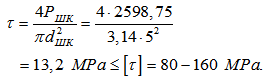 It is visible that the condition of durability is satisfied.
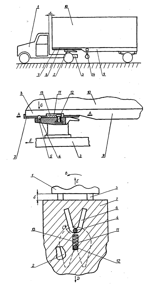 | Figure 8. Соnstruction of the saddle device according to the patent RU2229996 |
 makes 80 mm, also made of steel 45, thus, tangent tension in its equatorial section will be defined:
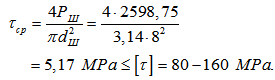 And in this case it is visible that full-sphere durability on a cutoff is provided. It was marked above that the compression spring of 13 (fig. 8) for a considered case is in not deformed status and 25987 N. V effort is made it an initial timepoint when the road train enters turn, this spring will begin is elastic to be deformed, because of relocation of a full-sphere 4 on the curvilinear notch 6 and, therefore, loading enclosed to it shall exceed value of 25987 N. Proceeding from it, and also considering dynamics of process of movement of the road train, for calculation of geometrical parameters of a compression spring we will accept initial working effort compression providing it equal
  29000 N exceeding
  25987,5 N by 1,1 times and using a known formula 11 we will determine diameter of a bar of a spring coil of compression having round section:
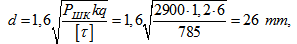 where: к – the coefficient of curvature of a round is accepted equal 1,2;q – the character of a spring is accepted equal 6;According to GOST 2771-81 we will finally accept diameter of a bar for extension spring manufacture equal 26mm, then average diameter it will be equal to D0 = qd = 26•6 = 156 mm, and outside diameter D = D0 + d = 156 + 26 = 182 mm. Rigidness of a spring in this case will make С = 145 kg s/cm and reading that the rigidity modulus for the selected steel is equal to G = 8105 kgs/cm2 working number of spring coils it is possible to determine by dependence:
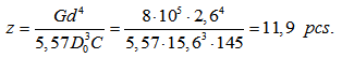 We will accept finally 12 rounds and then in case of a round step equal t = 54 mm spring length in completely its oblate status will be equal to L0 = 12•26 = 312 mm, and in the free status of LС = 648 mm. We will make spring check on durability on the allowed tangent tension on a formula:
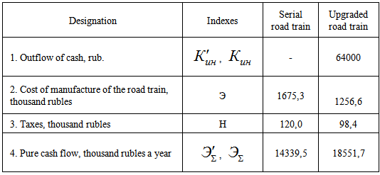
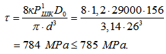 It is visible that the condition of durability is satisfied.Considering constructive diversity of the modern types of road trains being exploited as in our country and abroad, the program in the Delphi language is developed for carrying out calculations of the above parameters on the computer, allowed to set optimum and possible boundaries of increase in internal volumes of bodies of semi-trailers, without changing external initial overall dimensions of road trains, ranging from 2,6 to 3,1 m3, that is to increase their tonnage under operating conditions on the average by 5,2-9,3% that allows as on the average to increase profitability of transportations, in case of their run to 1000 km, for 8,6-10,3%.For the analysis of efficiency of implementation of the offered development, we will give an example of determination of predicted value of cash flows in case of upgrade of one serial road train consisting of the MAZ-5432 car tractor and the MAZ-93971 semi-trailer. We will use the basic data provided to the tab. which are characterized by cash flows in case of device manufacture, for example, according to the patent RU2248903.
|
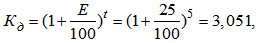 where: E-rate of return, we accept equal 25%;t-number of years of operation of an innovation, we set - 5 years.The received result shows that in five years each ruble enclosed in this project, will increase to 3,051 rub.It is known that the coefficient of discounting shall consider also inflation and risk factors (if only they aren't included in norm of discounting). Therefore the discounting coefficient taking into account inflation, but without risk, is determined by a formula:
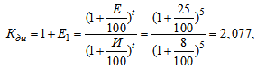 where:
  - predicted value of inflation is accepted equal the current year of 8%;Е1 - norm of discount taking into account inflation.Therefore, E1=2,077-1=1,77.It is visible that value of discount taking into account risk is less than value of coefficient of discounting without its account. It is connected to that inflation corrodes monetary mass. Taking into account the correction we will expect an index of coefficient of discounting risk on dependence:
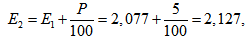 where: Р-the correction coefficient setting a risk degree.As road train already available in production is upgraded, we select the minimum rate of risk in the amount of 5%.The index characterizing time of payback of capital investments, the payback period of the project which we will determine by dependence serves:
 where:
  total investment in innovations;
 summary result (cash flow).Based on the above it is visible that within 3, 4 years this project will cover all expenses connected to implementation of the upgraded road train.
4. Results of Research
- Based on the above it is possible to draw the following outputs and sentences:1. At the moment, both in our country and abroad widespread heavy road train consisting of cars, trucks and trailers. These trains are designed to carry a variety of general and perishable and bulk cargoes. For interfacing these units are articulated tractor unit interacting with the kingpin, rigidly fixed on the supporting plate frames trailers. Despite the high efficiency of these trucks, constantly exposed to the latest design improvement and modernization of their units and parts.2. Analysis both domestic, and foreign constructions of road trains shows that the last possess the essential shortcoming, being that, due to existence of dead space located between edge part of a cabin of the car tractor and a body of the semi-trailer necessary for the free angular turn of the semi-trailer in case of maneuvering of the road train, efficiency of use of tonnage of the last is insufficient. 3. Considering the above at the level of inventions (RU2214338, RU2248903, RU2240944, RU2229996, SU1169874, SU1692883, SU1230911) technical solutions of the devices allowing in an automatic mode in case of a description of the heavy-load road train in curve sections of a way to increase distance between edge part of a cabin of the car tractor and a body of the semi-trailer a redeveloped, and in case of an input in a direct section to reduce the last. Estimated diagrams are developed for establishment of rational geometrical and kinematic parameters of the considered row of such devices and their constructional characteristics are calculated. So, the carried-out calculations, in relation to the road trains which tractors are supplied with the above devices automatically regulating gaps between cabins of tractors and edge parts of bodies of semi-trailers of the models ODAZ-794, ODAZ-795, ODAZ-935, ODAZ-857B, N12ALKA, SAVUAYaRD and IWT showed that internal volumes of their bodies in comparison with the serial increase in limits from 2,86 m3 to 3,7 m3, that is tonnage of semi-trailers can be increased on the average by 5,4% ÷ 9,6%.4. Results of research are recommended to the domestic and foreign motor transportation enterprises, automotive industry and scientific and designer subdividings working in the field of automotive industry for study and the analysis of the offered constructions for the purpose of possible further their implementations in practice.