Slivinskij E. V., Radin S. Y., Gridchina I. N., Pakhomova E. V.
Yelets State University I. A. Bunin, Yelets, Russia
Correspondence to: Slivinskij E. V., Yelets State University I. A. Bunin, Yelets, Russia.
| Email: |  |
Copyright © 2014 Scientific & Academic Publishing. All Rights Reserved.
Abstract
This article presents the results related to the development of several promising designs towing devices used on passenger cars and for transporting lightweight trailers. Such devices have a simple structure, easy to operate and eliminate unhooking lightweight units train in motion. For these structures created at the level of inventions developed computational schemes and calculate the main rational and geometrical parameters, allowing to provide a constructive and operational reliability of lightweight trucks widely used in practice, both physical and legal entities. Develop recommended research and industrial structures in the field of automobile engineering with a view to further study and possible implementation in practice.
Keywords:
Ball head, Bracket slot retainer spring, Drawbar, Road trains towing hitch, Trailer
Cite this paper: Slivinskij E. V., Radin S. Y., Gridchina I. N., Pakhomova E. V., Upgrade Hitch for Lightweight Road Trains, International Journal of Traffic and Transportation Engineering, Vol. 3 No. 2, 2014, pp. 119-131. doi: 10.5923/j.ijtte.20140302.08.
1. Introduction
It is known [1-3] that for performance cars in practice, the most effective method is to use a different purpose and construction trailers. These trains are not only used by motorists, but also various commercial structures of representing yourself in a market economy, small and medium business. Manufacturing practices and the operation of these trains, both in our country and abroad shows that the growth of passenger car fleet inevitably promotes consumer different purpose trailers used for domestic purposes, and recreation. Especially widespread in the train car with the composition of residential trailers, known as caravans abroad. For example, in the USA operated by more than one million residential trailers for cars, which is about 150 trailers per thousand passenger cars, 50 in Germany, 60 in the Netherland, etc. In our country, the most widely used cargo trailers, with cars of mounted models such as VAZ, GAZ, etc. It is clear that the establishment and operation of such lightweight trains emphasizes their safety, especially on roads with heavy traffic.In the classification of their trailers into account the following key indicators - private and gross weight, load capacity, number of beds (for caravans), dimensions, number of axes, a way to connect with the car and the quantity and quality of equipment, determines their comfort. When choosing a trailer for this model car based on the following considerations - for which transport is supposed to use a trailer, the opportunity cost of storage and the trailer. For example, for the purposes of tourism, long-distance road trip provides the greatest convenience of living non-folding trailer with a hard body. However, this significantly limits the trailer train speed and maneuverability, and requires special storage space for long periods of time in between trips. When transporting a variety of goods, which by their bulkiness and weight can not be transported in the trunk of the car, use cargo trailers. For boat trips or water sports using special trailers for boats, etc.Most of the construction trailers are welded steel frame consisting of two longitudinal and cross. In the middle of the frame welded brackets for wheel suspension and shock absorbers. To the front end spar attached locking device installed on the frame -metal body with tarpaulin. To car could tow a trailer , it is equipped with a standard towing hitch on OST37.001.096 - 77, made in the form of a ball, interconnected with a locking device of the trailer (Fig. 1).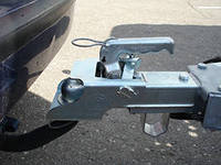 | Figure 1. General view of the trailer coupling lightweight trains |
The most important indicator of the trailer coupling car is the ability to withstand horizontal and vertical dynamic loads transmitted by the locking device of the trailer. In common practice, a variety of design options locking devices, and the most widely used devices with detent ball head using the wedge [1, 5].To tow a trailer with a car equipped with such a device, previously removed from the pin hole and lock lever. Then fed the way up the latch and is withdrawn in the forward position lever. This action contributes to the movement of the lever to the rear position of the wedge, releasing the ball socket hole. Then, holding the lever in the highest position, put a locking device on the ball head of the towing device and translate the lever to its original position. Thereafter lowered lock in the down position to align the holes in it, and cotter pin and lever their splint [1].Analyzing the above operation grappled with a trailer can be seen that, firstly, it is labor-intensive, requires a series of successive operations and agreed the best thing is that all parts of the device described in the end keyed manually. It is known that not paying enough attention to the procedures eventually locked in the driver may forget to install the cotter pin, or the last, due to a lack of divorce him fixing parts may subsequently spontaneously fall out and then the consequences unhooking units train in motion can be very serious, until injury people were fatal.Based on the above it is clear that all known constructions locking devices cars do not meet modern requirements for use of the rolling stock, which today has a high speed. And since the probability of failure of couplings cars and trailers exists, the task of ensuring safety is very important.Given the importance of this problem, they at YSU I.A. Bunin at the Department of Applied Mechanics and Engineering Graphics conducts applied research on "Dynamics, durability and reliability of the transport machinery, road construction and agricultural machinery, as well as standard and non-standard industrial equipment for example Black Earth region of Russia" and one of the its sections is the development of technical means to improve traffic safety trains consisting of passenger cars and trailers.
2. Goals and Objectives of the Study
Analyzing the above it is clear that all locking devices known structures, including for cars, do not meet modern requirements for use of the rolling stock, which today has a high speed. And since the probability of failure of couplings cars and trailers exists, the task of ensuring safety is very important. Therefore the aim of this study is to:1. Development of advanced designs towing devices for cars and trailers, is simpler in design and have high reliability in an operational environment.2. Development of design models for the study of force loading of coupling devices and mathematical models in order to support the kinematic and geometric parameters.3. Technical and economic assessment of the proposed technical solutions for the possible use of the proposed designs in practice.
3. Research Methodology
Analysis of multiple bibliographic sources, as well as domestic and foreign patents has allowed to develop a promising coupling for such trains, which is recognized by the invention (RU2230675). The device comprises (Fig. 2) from the body of the drawbar, which is stationary, but the upper portion is movably placed a ball head, a hollow covering its circumferential projection formed on the flat bottom surface of a spherical head made integrally with the bracket rigidly fixed to the passenger car. At the top and bottom of the ball head has a coaxial, vertically spaced holes in which you installed the connector pin, having different diameters, as well as a spherical head and a recess under the ball, spring-loaded spring, with the nut installed in the holes in the bracket.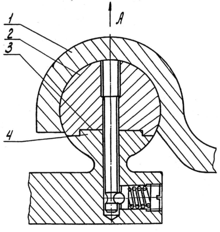 | Figure 2. Device Patent RU2230675 |
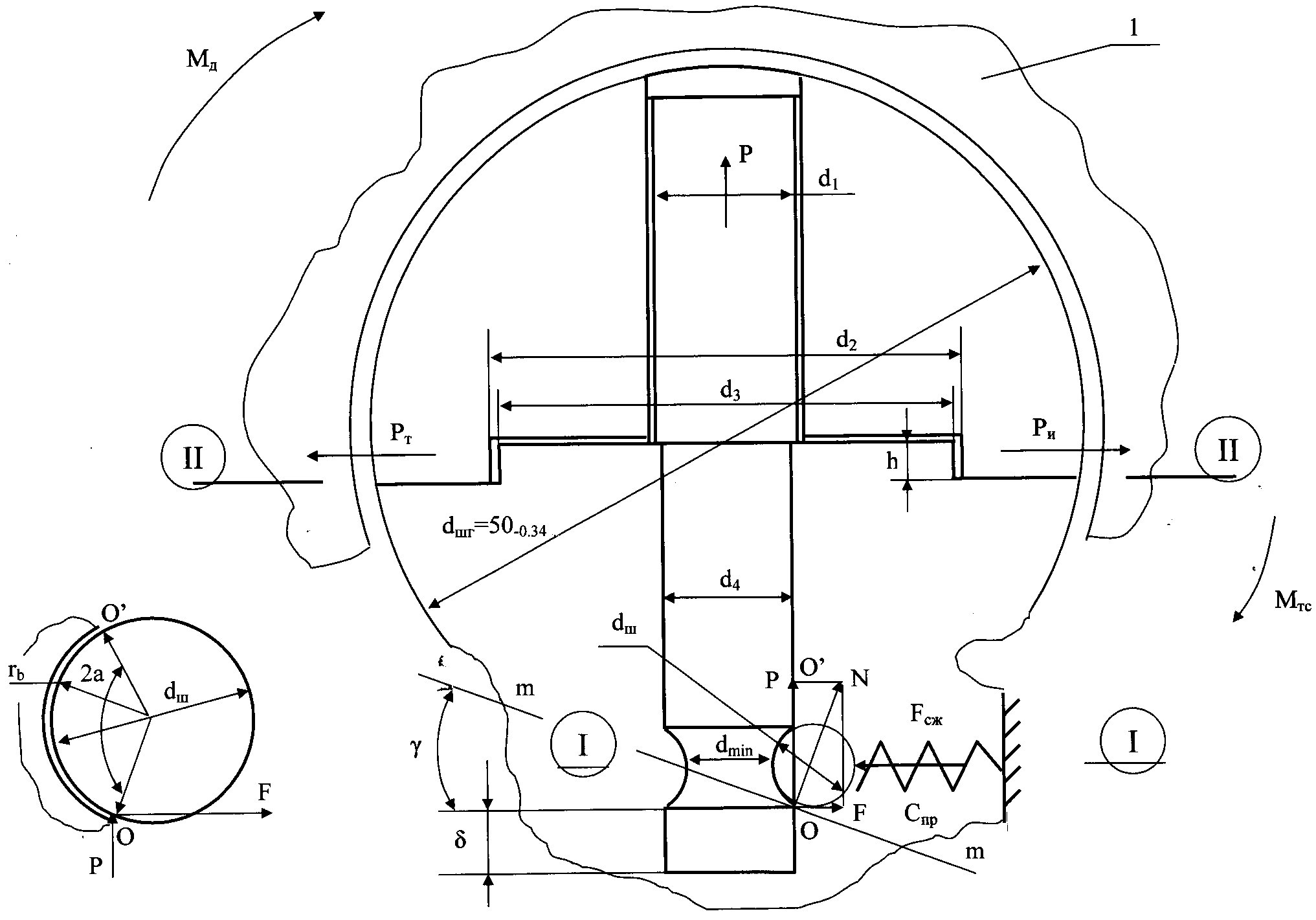
In the case when subject to prolonged storage of the trailer, or when it is necessary to make disengage for technological reasons, trailer mounted on a horizontal platform and spun nut retainer. Once the action of a spring on his ball weaken, manually raise the drawbar body, with the top of the ball head, together with the connecting finger also moves in the same direction due to the fact that the diameters of its different when it is released from the recess of the ball is not spring loaded compression. Once the connector pin cavity exits the bottom of the hole the ball head, and unhook the trailer can be done manually or some other way to move his place of temporary parking or sludge. Tractive connection links for trains produce tighter operation only in reverse order.To determine the rational dimensions of the parts of the trailer coupling for existing geometric characteristics of a spherical head, regulated OST37.01.096-77 for passenger cars, the design scheme developed its force loading and calculations in relation to train consisting of cars VAZ-2107 car and truck uniaxial trailer model MMZ - 81021, respectively having full weight 1430 kg and 300 kg. The maximum permissible speed trains VA = 80 km/h (22.2 m/s).The calculation of the projection of a spherical head crushing, connector pin on the strength of the dangerous section and perform the selection of the stiffness of the spring retainer. To accomplish this you need to know the value of design load Ркр(max), arising in the coupling, which can be determined, assuming that the train movement is severe on a rough road at the height of irregularities 2q0 = 12 cm and at a wavelength of L = 25 m, depending on the [5]: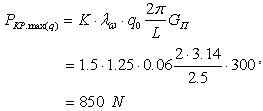 | (1) |
where,  − is the limit of dynamic coefficient; K - additional dynamic factor that takes into account the impact of gaps in the towbar.According to a number of studies on the force loading hitches trains, both in our country and abroad believe that the efforts of the Ркр(max), usually less effort Pm when starting off on average by 34%, while 47% inhibition of Pт. Consequently, in an effort locked in this case can be taken as Pт = 2500 N, and when braking Ртор = 1175 N. It is evident that the greatest value of the force applied to the drawbar trailers, is its value at the time of pick-up and equal РT = 2500 N. Define cm arising on the generator surface protrusion d3, whose σcм bearing stress height h, the known dependence:
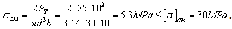 | (2) |
where, d3 - diameter of the protrusion formed on the bottom of the ball head, is assumed to be structurally mm; h - height of the projection is equal to 10 mm, also adopted a constructive; σcм - allowable stress for [σ] carbon steels with heavy duty shock, assumed to be 30 MPa.To calculate the strength of the connecting pin in section dmin contact with the ball retainer attached Рв. Experimental σр moments where MTS, MD and Pв force any tensile stress studies in the field of loading towing devices cars show that the vertical components of the dynamic loads on the connecting fingers on average, with a probability of less than 0.1, does not exceed 20% of the longitudinal components of efforts manifested in the breakaway torque train with places and therefore , in this case value Pв can be taken to be 500 N. it is also constructively taking the geometric dimensions of the connecting pin d1 = 20 mm, and dmin = 12 mm under the bead retainer dш = 8.0 mm, the tensile stresses in the compute section of this by known relationship : | (3) |
As a material for the [σ]p = 200 MPa. The result shows that the connector pin choose Steel 45 strength condition in the cross section of the connecting pin holds dmin. Since the vertical component of Pв applied to the coupling pin, can reach a value of 500 N, then from its action on the ball there normal N and radial components of F (Fig. 3). Both of these forces tend to overcome the force of the compressed spring stiffness СПР and such strength can be determined from the dependence: | (4) |
 | Figure 3. Design scheme |
In this case it is clear that there was to deformation of the spring must be satisfied F ≥ N or Pв≥ Ntgα, where an angle of α- ball finger recess selected constructive and equal 380. Using the reference data according to GOST 13765 - 86 , the following geometric characteristics of the spring under load its capacity of 650 N: Dнар = 20 mm, wire diameter 3.5 mm, length 30 mm spring, stiffness Спр = 4.5 kg / mm material steel 60S2 with τ = 57 kg/mm2 .It is clear that the failure in strip may be the case when the spring is fully compressed and under the influence of the maximum load Pв Chance slice the ball along its cross-section. The diameter of the cross section in the plane selected 5.2 mm, and then the shear stresses in this section to determine: It can be seen that the allowable stress [τ] Wed ШХ15 for steel, which made their rolling elements for bearings, 14.8 times higher than the calculated value. Consequently, in this case, the strength condition is satisfied and unhooking car and trailer completely excluded.To automate the calculations developed a computer program using the language Delphi, which was tested during the complex calculations of this study.Consider another perspective drawbar for such trains, which also recognized the invention (RU2397881).So in figure 4 shows a general view of the towing device in cross section. This towing hitch drawbar consists of drawbar of trailer 1, with a hole 2, cover the top 3 of the ball head, in the cavity 4which has projections 5. The lower part 6of the ball head is rigidly connected to the arm 7 mounted on the towing vehicle and provided with a projection 8, which made recess 9 provided with through slots 10. The bottom portion 6 of spherical head is placed a ball retainer11, spring-loaded by a compression spring 12, and on top 3of the ball head holds a hemispherical shaped indentation 13. The upper portion 3 of ball head is located a square shaped hole 14.
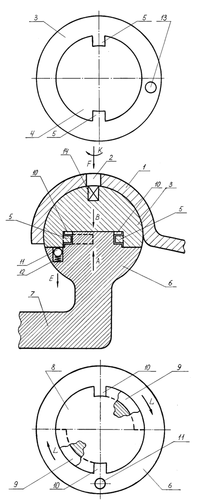 | Figure 4. Hitch patent RU2397881 |
Powered drawbar follows. Figure 4 shows the drawbar at the beginning of fixing the place tractive connection of the towing vehicle and trailer when drawbar 1 of the last together with the upper part 3of the ball head laid on the bottom 6 of ball head, and so that the projections 5 formed in the cavity 4 the upper part 3 of the ball head, were placed in the through slots 10 present in projection 8 of the lower lip 6of a spherical head. In this case, the upper part 3 ball head, in such a situation, drowned by the arrow E Ball retainer 11 elastically deforming compression spring 12 in the same direction. Thereafter, the driver of a vehicle - tractor by arrow F enters the hole 2of the drawbar, and then in a square shaped hole 14 shaped like a key (in Figs. Key not shown) and rotates clockwise by K the upper part 3 of a spherical head relative to the fixed lower part 6of the ball head. When the protrusions 5, the upper part 3of the ball head is moved in the recesses 9, the bottom portion 6 of ball heads of the arrows L until occupy the extreme position in the latter. Simultaneously in the same direction together with the upper part 3 of the ball head is moved formed therein, and a hemispherical shaped recess 13, which, in turn, comes into contact with a ball retainer 11. Once such contact occurs, the ball retainer 11 by the action of the compression spring 12 moves in the direction opposite the arrow E and securely fix the upper part 3 of the ball head relative to the bottom part 6 of the ball head. As a result, the two parts 3 and 6 are of a spherical head secured to one another. Thereafter, the driver removes the key in the opposite direction of the arrow F and the vehicle is ready to move. Uncoupling train units for these actions are performed in reverse order and when the protrusions 5 formed in the cavity 4 top 3 of ball head after her turn in the opposite direction of the arrow K, but with some effort required to release ball detent 11 of the hemispherical shape of the recess 13, will in space through slots 10 of drawbar1, together with the upper part 3 of the ball head is lifted in the direction opposite the arrow F. As a result, uncoupling train units implemented. Hereinafter described processes may be repeated several times.Analyzing this construction shows that the most responsible part of her is a ball retainer, which must be securely fix the upper part of the head relative to the bottom of the ball. It is known that structurally Ball retainer has some drawbacks.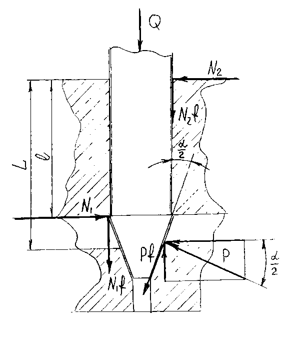 | Figure 5. Estimated latch circuit |
For example, in order to avoid jamming of the ball must be immersed into the recess 13 so that at the extreme position of its center is not the last edge reached by a distance, which limits the depth of the retentive recess, at the same time centering of the spring on the ball is non-rigid and lock it loss at disengage coupling difficult. Therefore it would be appropriate to use in the proposed technical solution, not the ball, and a tapered pin. Consider the force loading conical retainer using the calculation scheme shown in Figure 5. When rotation angle of the drawbar on a conical surface retainer arise force F tending to lift the lock, which can be determined according to [3]: | (5) |
where Q - force by the spring retainer; α / 2 - half of the central angle of the cone. Under the action of the force P, the extreme points rails lock any reaction N1 and N2, which can be calculated by the formulas: | (6) |
Lift the latch will counteract the force of friction and N1f, N2f (where f - coefficient of friction), and the axial component Pf arising at the point of application of force F and equal Рfcos α / 2. Then the equation of balance of these forces can be written as:  | (7) |
Substituting into this equation the values of N1 and N2, we obtain the relationship: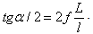 This ratio determines the threshold angle α, which is still possible when lifting the latch, and, consequently, the dissolution of the parts of a spherical head. For lower values of this angle is obtained self-locking compound. Given the small geometric dimensions of the ball head (according to OST 37.001.096-77 diameter hitch ball trailer hitch car is 50-0,34 mm) we will lock with a small departure cone relative to the guide, which L / l is 1.2 - 1.3, and the coefficient of friction f = 0.1. Then substituting these values into the expression 1, we obtain that α / 2 = 150, and the angle at the vertex of the cone α = 300. However, taking into account possible fluctuations in the friction coefficient under operating conditions for reliable self-locking and, consequently, reliable fixation of the halves of a spherical head relative to each other permanently assume the cone apex angle equal to α = retainer 250.For the economic evaluation of the proposed technical solutions used method of financial and investment analysis and audit of the introduction of new technology. [4] The baseline sample taken train consisting of cars VAZ-2107 car and truck models uniaxial trailer MMZ - 81021. Statistics emergencies related unhooking cars with trailers, shows that their number in the total accidents occurring in the Russian Federation in the year is about 6.5%. The average cost of repair of one semi-trailer from such failures is 10.3 thousand rubles. And mean time to failure of such reaches to 64.0 thousand km. According to service enterprises Lipetsk region are semi- annual mileage from individuals and legal entities engaged in transportation companies created on the basis of small businesses is an average of 48.7 thousand km, with the standard of its useful life of 7 years. Based on the above, as well as using the data in Table. Define annual economic benefit derived by the enterprise from the introduction of the service, for example, patent RU2397881, allowing one to enhance the durability of the semitrailer by eliminating emergency situations associated with this type unhooking trains.To do this, use the following indicators. 1. Coefficient of comparative economic efficiency, determined from the dependence:
 2. Coefficient of reduction of costs compared to a run trains
 3. These costs of road trains:a) basic --
  b) modernized
 4. These costs are subject to the same reduction factor production volume coupling devices:
 Based on the above calculation will produce the profits that the company will receive from the release of one of the upgraded hitch depending on:
 .Now we consider in our opinion more reliable and simple solution also recognized the invention (patent RU2493996).Figure 6 shows a side perspective view of the trailer coupling, and a top view of a cross-sectional space of its connection to the trailer tongue.
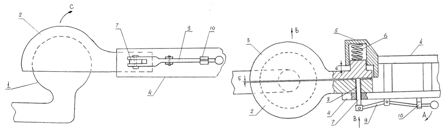 | Figure 6. Trailer coupling of lightweight trains |
Hitch train consists of ball head 1 attached to the car and located between one part of the hemispherical head 2 and the other part of the hemispherical head 3 with clearance δ. One portion of the hemispherical head 2 is rigidly secured to the drawbar 4 and the other hemispherical portion of the head 3 is movably located in a guide 5 rigidly attached to the drawbar 4 and biased helical compression spring 6 relative to the guide 5. Another part of the head 3 is provided with a hemispherical rod 7 is movably disposed in a hole 8 formed in a hemispherical portion of head 2 and the drawbar 4 and the rod 7 itself is pivotally coupled to the bell crank 9, provided with a stopper 10.| Table 1. Main design parameters |
| | № | Performance | Designation | Unit of measurement | Base road-train | Modernized road-train | | 1 | The number of trailers coming in repair | А | PCs | 1 | 1 | | 2 | Mileage trains to emergency repairs | Д | Thousand km | 64.0 | 340.9 | | 3 | The cost of repair the trailer | С | RUB | 42300 | 34000 | | 4 | Capital expenditures on the repair unit | У | RUB | 65000 | 78000 | | 5 | Normative coefficient of efficiency | Ен | - | 0.15 | 0.15 |
|
|
Powered drawbar train follows. Figure 6 shows a device in working transport position when the vehicle and trailer are connected together and they represent a two-tier trailer. In that case, if you want to make this train uncoupled units, perform the following operations. Dissolving the stopper 10 which fixes the two-armed lever 9 is in the position as shown in Figure 6, two-armed lever 9 is rotated along arrow A and then it is acting on rod 7 by arrow B, moves in the same direction of the other part of the hemispherical head 3 in the guide 5, compressing a helical compression spring 6. Such other moving parts of the hemispherical head 3 increases the gap δ between the latter and the fixed part of one of the hemispherical heads 2 to such an extent that the gap is selected to be δ. Eventually ball head 1 will be free in the space formed by a hemispherical head part 2 and another part of the hemispherical head 3. Once this happens, the drawbar 4 widely known way to manually turn on the arrow C, thereby disengage said clutch. Thereafter, when implemented will disengage under the action of a helical compression spring 6, the other hemispherical head 3 returns to its original position and the two-armed lever 9 is fixed by the stopper 10 to afford angular rotation in the direction opposite the arrow A. It should be noted, a guide 5 and, consequently, and interconnected with her other part hemispherical head 3 can be either round, rectangular and another section that would have contributed to the formation of such a translational kinematic pair. Next tractive connection process takes place in reverse order and both of them later can be repeated several times.To determine the rational dimensions of the parts of the proposed towing device for existing geometric characteristics of a spherical head , regulated OST37.01.096 -77 for passenger cars, the design scheme developed its force loading and calculations in relation to roadtrain consisting of car VAZ-2109 and cargo uniaxial trailer model MMZ - 81021 , respectively having full weight 1430 kg and 300 kg. The maximum permissible speed trains VA = 80 km / h (22.2 m / s). Analysis of the structure of the proposed technical solutions and his work showed that the most responsible part it is a compression spring 6 (Fig. 6), which trains in motion and under dynamic loads exclude the possible movement of the hemispherical head 2 rigidly mounted on the drawbar of the trailer 4 respect to the other part 3 is movably mounted in the guide 4 5 drawbar. Carry out the calculation of such parameters for this spring as well as in the previous case ( see formula 1) believe that the magnitude of the design load equal to the Ркр(max) = 850 N and Pm = 2500 N and Ртор = 1175 N.Clearly, in this case, the load is applied in the longitudinal plane of symmetry of trains, the movement of the hemispherical heads 2 and 3 is possible. In our case, moving hemispherical heads 2 and 3 is possible only in those cases when there is wagging the trailer and that's when there are dynamic component acting in the transverse plane of the trailer is capable of elastically deformed compression spring 6 and move the hemispherical head 3 relative to the head 2, which will disengage train links. It is also known [2, 3] that in practice manuals automotive full trailers efforts arising grappled with their wobble do not exceed 15% of the longitudinal components of dynamic forces in our case they can be assumed to be equal to 400 N. Using the data of [4], according to this effort with a safety factor of 1.5 in accordance with GOST 13765-86 selected spiral helical compression spring with the following parameters: operating force Рраб = 560 N, the outer diameter D = 40.0 mm , wire diameter d = 5.0 mm, the number of turns n = 9.5, free spring height H = 103 mm, deflection at full compression spring F = 48.0 mm, spring wire material in accordance with GOST 13765-86 P , the total voltage at full compression spring [τ] = 0.6 MPa. No less important parameter is the force generated by the driver and train applied to the lever 9 (Fig. 6) to produce or disengage the clutch units train. It is known that such an effort by the standards back should not exceed 150 N , this requires that the gear ratio of the bell crank 9 would equal U = 3.7 ie If one arm of the bell crank chosen equal to 100 mm is more necessary to perform length l = 370 mm.Analyzing the above it is clear that in practice in the preparation of lightweight trucks trailers can be as different in design and have different weights and lifting performance, and on this basis in order to enhance the operational capabilities of the proposed device, in each case on its trailers must be installed towing device designed according to the weight of trailers and their destination. At the same time for the selection of a rational design of a wide range of required testing of specimens in the operating conditions , and only after that we can finally prove the optimal geometric.Consider another no less interesting perspective hitch for lightweight trucks, which is also protected by RF patent for an invention (RU2397883).This design is shown in Figure 7 and is a modernized drawbar sectional. | Figure 7. Hitch in the context of patent |
Hitch consists of arm 1 of the trailer coupling of the car, which is a common part to the lower part 2 of ball head. The lower part 2 of the spherical head is provided with clamps 3 which are arranged in the recesses 4 formed in the upper part 5of the spherical head. The lower part 2 of the spherical head is provided with pivot 6 interconnected by means long-stroke carving 7 mating with carving formed in the upper part 5 of the ball head and its hole 8 is made of square cross-section which interacts with the finger 9 are movably mounted in the drawbar 10, and a spring-loaded compression spring 11. The finger 9 is provided with a lever 12 having a cavity 13, in contact with the retainer 14 mounted to the drawbar 10.Powered drawbar follows. Figure 7 shows the drawbar when the trailer (in fig. not shown), or rather its drawbar 10 is connected via the top 5 of the ball bearing and the lower part 2 of the ball through the bracket 1 trailer coupling with car vehicle (in Fig. not shown), as is usually the case in serial constructions. For uncoupling the vehicle and trailer must install trailer on level ground with one hand, pushing the finger 9, move it to the arrow A until it engages in the opening 8 square and then turn the lever 12 in the counterclockwise direction about the axis yy of the device at an angle 1800. This angular rotation of lever 12 provide rotation of the upper part 5 of the ball head of the arrow B, and since it is linked via long-stroke carving 7 with the lower part 2 of the ball head, the breaking resistance of the angular rotation of clamps 4 is unscrewed from the rod 6 in the direction opposite arrow A and together with the drawbar 12 to move in the same direction. Once part 5 of the ball head threaded rod 9 leave the car ready to move, and the trailer stays in place, i.e. uncoupling train units produced. Coupling units train follows. Vehicle supplied by reversing direction C. As soon as the lower part 2 of the ball head, or rather it would be the rod 6 below the top 5of the ball head, the latest in conjunction with drawbar is lowered by arrow A so that the threaded surface of both sides of 2 (bar 6) and 5 coincide and then the handle 12, after moving along the arrow A the finger 9 before entering it into the square hole 8 is rotated in the direction opposite to the direction arrow B that causes rotation of the upper part 5 of the ball head, thereby winding on shaft 6 of the bottom 2 of the ball head. Once the thread parts 2 and 5 will be selected before the end, both clips 3 are included in the recess4that securely fasten together the two parts 5 and 2 of the ball head. Thereafter, under the action of the spring 11 finger 9 together with the lever 12 occupy the position that is shown in Figure 7, and the lever 12 in this position so as to be fixed against rotation retainer 13. Hereinafter described processes may be repeated several times.Analysis of the presented design shows that uncouple this tractive connection can only happen when a kinematic pair " drawbar 10 - the top part of the ball 5 " due to lack of lubrication in the contact area due to their jamming occurs circumferential friction force which exceeds the retention time resistance moment created clamps 3 (see Figure 7). We present a numerical example of the calculation of these loads, for example, to train consisting of cars VAZ-2107 car and truck models uniaxial trailer MMZ - 81021, respectively, having the full weight of 1430 kg and 300 kg using the calculation scheme shown in Figure 8. The maximum permissible speed trains VA = 80 km / h (22.2 m / s).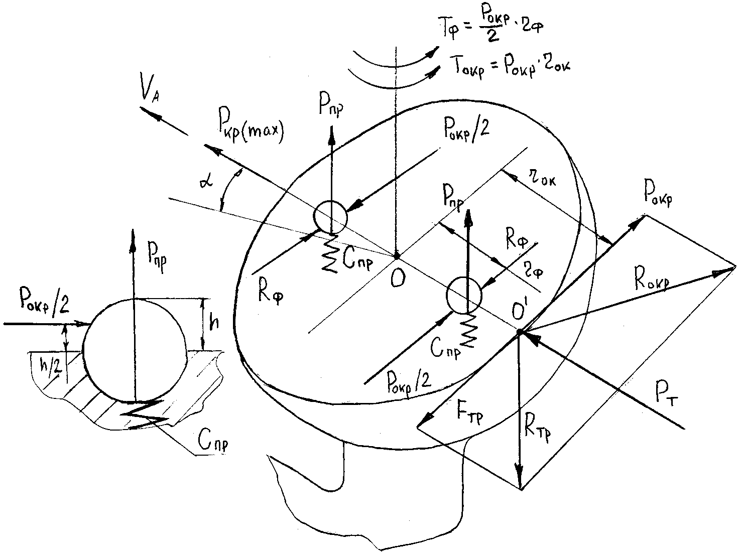 | Figure 8. Design scheme |
As in the previous case, we assume that the magnitude of the design load is Ркр(max) = 850 N, and Pm = 2500 N and Ртор = 1175 N(see formula 1).It is seen that when braking trains possible angular rotation of the upper part 5 of the ball, which can lead to disengage the coupling. This angular rotation of the drawbar 10 by an angle α, will contribute to the district Рокр force that is greater in magnitude of the friction force generated between Fтр drawbar 10 and the fixed upper part 5 of the ball relative to the bottom 2 and equal Fтр = Ртор= 117.5 • 0.15 = 176 N it can be seen that the friction force is small in magnitude and, moreover, that each of the three clips (see Figure 7) is loaded with a force of Рокр/ 2 = 88 N. As a first approximation, we assume the workload РПР compression springs must be somewhat greater than the force Pokr / 2 = 88 N capable to cause its elastic deformation and the work retainers while structurally assume that it is attached to the retainer is not in its equatorial plane section and at half its height (see Figure 8). Then we can choose the specifications of the springs by using the table data sources [4], namely outer spring diameter of 10 mm, wire diameter 2.0 mm coil pitch of 4.0 mm, the height of spring 16 mm, the working load of 140 N, spring material steel according to GOST 14959-79 60S2. Denial of coupling can also occur in the case where the spring clips for one reason or another can be fully compressed and then under the influence of the maximum load Рокр chance slice ball retainer for its cross-section. The diameter of the cross section in the plane to establish constructive to 6.0 mm, and then the shear stresses are determined in this section: | (8) |
It can be seen that the allowable stress [τ] Wed ШХ15 for steel, which made their rolling elements for bearings, 11.3 times higher than the calculated value. Consequently, in this case, the strength condition is satisfied, and unhooking vehicle and trailer will be completely eliminated.Consider another construction hitch invention also recognized (RU2290322).Figure 9 shows a general view of the side of trains, and a cross-sectional part of the structure at the interface between the bracket and tow bar trailer hitch car.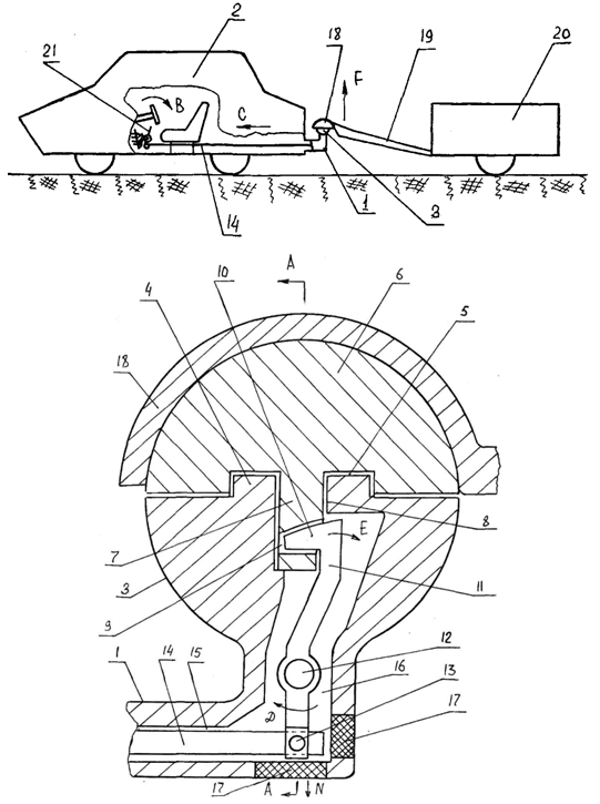 | Figure 9. Hitch made on patent RU2290322 |
The proposed technical solution represents a bracket 1of traction coupling device of the car 2, executed for a single whole with the heel 3 of spherical heads supplied with a circular ledge 4, is located in a circular cavity 5 in the upper part 6. The latter, also provided with a rod 7 located in thehole8 of the bottom 2 of the ball head. The rod 7 has a groove 9 in which is placed the cam 10 of the bell crank 11 is pivotally mounted on the axis 12 and connected by a hinge 13 fixed to the rod 14 in the longitudinal bore 15 of the bracket 1. Longitudinal channel 15 is associated with the vertical channel 16 is also formed in the bracket 1 and the bottom 2 of the ball head.In bracket 1 are technological holes, which are inserted into the plug 17. The upper part 5 of the ball head movably arranged in the housing 18 of the drawbar 19 of the trailer 20. Link 14 and its other end pivotally connected to the two-arm lever 21 installed in the car 2.Powered drawbar follows. To disengage the train (in Figure 9 units train car 2 and trailer 20 are interconnected by means of drawbar 19 and the bracket 1) dismissing the driver of the car 2 retainer bell crank 21 (Figures lock bell crank 21 is not shown because its design is widely known practice) turns it by arrow B, which provides for movement of rod 14, arrow C, and since it is connected via hinge 13 with the two-arm lever 11, then it receives the angular rotation according to the arrow D by turning on the axis 12. Since the two-armed lever 11 is rigidly connected to the cam 4, it exits from the groove 9 of the rod 7 by the arrow E. When the cam 10 fully leaves the groove 9, the driver fixes widely known in the art two-armed lever 21 comes out of the car and manually moves drawbar 19 of the trailer 20 according to the arrow F together with the housing 18 and the upper part 6 of the ball head. Tractive connection links for trains, this operation is carried out in reverse order. In case of repair or parts described device preventing its moving parts, the plug 17 is removed (the plug 17 can be formed as, for example, a cut- in plugs are threaded and the arm) and dismantle the axis 12 by arrow, for example, G. Likewise, hinge 13 disconnects then moved along arrow N two-armed lever 11. Make the necessary inspection or replacement of those parts, the assembly is carried out in reverse order. Subsequently described processes may be repeated several times.To determine the rational dimensions of the parts of the trailer coupling for existing geometric characteristics of a spherical head, regulated OST37.01.096 -77 for passenger cars, the design scheme developed its force loading and calculations in relation to roadtrain consisting of cars VAZ-2107 car and truck axle trailers model MMZ - 81021 with total masses, respectively, and 1430 kg to 300 kg. The maximum permissible speed trains VA = 80 km / h (22.2 m / s). The calculation of the projection on a spherical head crushing, two-arm lever control rod in tension and its console (cam) in bending. As in the previous case, we assume that the magnitude of the design load is Ркр(max) = 850 N, and Pm = 2500 N and Ртор = 1175 N(see formula 1).Proceeding from these load values define bearing stress σcm arising on the generator surface protrusion d3, whose height h, depending on: | (9) |
where d3 - diameter of the protrusion formed on the bottom of the ball head, is assumed to be structurally mm; h - height of the projection is equal to 10mm, also adopted a constructive; [σcm] - allowable stress for carbon steels with heavy duty shock, assumed to be 130 MPa.To calculate the two-arm lever control rod for strength, where her sections under the action of Рв. use the following data of [1, 3]. Since σр tensile stresses arise Pв experimental studies in the field of loading towing devices cars show that the vertical components of the dynamic loads on the connecting fingers on average, with a probability of less than 0.1 , does not exceed 20% of the longitudinal components of efforts Pm = 2500 N, manifested at the moment breakaway train with seats. Consequently, in this case the value of Pв can be taken as 500 N. Given that the bell crank gear ratio can be taken constructively U = 2 then there will be carried out under axial load Рпр = 1000 N. Also we will constructively diameter rod d1 = 6,0mm as well as material for traction choose steel 45 GOST 1050-88 with [σp] = 200 MPa, and calculate the tensile stress in her section, 1050-88 with depending on: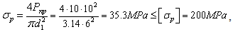 | (10) |
it is evident that the strength condition is satisfied.Since the vertical component Pв, applied to a two-armed cam lever can reach a value of 10∙103N then by the cam action of its rectangular profile having a height h = 12 mm there is uniformly distributed load
 , where l = 0.02 m working length portion of the cam the bell crank in the zone of its contact with the upper groove part of a spherical head. Then the equation of bending moment for this portion of the cam can be written in the form
 , and drag torque of the cam will be
  . Then the condition for the strength of the cam can be written as:
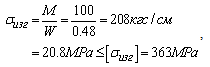 | (11) |
where [σизг] = 363MPabending taken by yield strength steel 45 GOST 1050-88 from which the double-arm lever is made integrally with the cam. It is evident that a margin of safety for bending the cam is 17.5, hence its strength and safety of operation of the proposed design of the locking device integral ball head the coupling is provided.And the latter is not less interesting design of the trailer coupling is shown in Figure 10, which is also recognized invention RU2493974.So the figures Figure 10 shows a general view of the trailer coupling side view of the hemispherical head of the drawbar with a cut in the longitudinal plane and his view of the ball head on.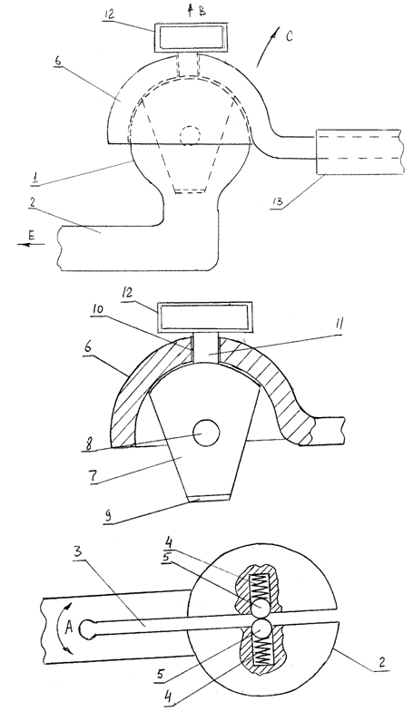 | Figure 10. General view of the tractive connection side, top and longitudinal section |
Hitch lightweight train consists of a ball 1 rigidly connected to the rod 2 and they made through slot 3. In a ball 1 set, resilient compression springs 4 ball retainers 5. Ball 1 covers hemispherical head 6, equipped with an emphasis trapezoidal shape 7 with a hole 8 and a pointed end 9. In the hemispherical head 6 has an hole10 in which shaft 11 is movably mounted on the stop rigidly fixed trapezoidal shape 7 on the handle 12 and its control. Hemispherical head 6 is rigidly attached to the drawbar 13 of the trailer and the rod 2 - to a car with a trailer forming a lightweight trailer.Powered drawbar lightweight train follows. In the engaged state drawbar passenger train is in this state, as shown in Figure 10. In this case, it is clear that the emphasis trapezoidal 7 by its hole 8 is located between the ball retaining groove 5 in a through slot 3 is securely connected the ball 1 with hemispherical head 6. When maneuvering the trains and angular displacements of its parts relative to each other in the horizontal plane of motion, the emphasis trapezoidal 7 rotates together with the ball 1, the axis 11 and the handle 12 relative to the hemispherical head 6, which creates conditions for train flexibility in the horizontal plane to achieve simultaneously excluding disengage it units. In the case of pitching oscillations, i.e. moving the train of links in the vertical plane of motion, the trapezoidal-shaped stop 7 is also has free movement is in conjunction with a hemispherical head 6 along the through slot 3 formed in the ball 1 and the shaft 2. When lateral pitching vibrations when the trailer gets some angular rotation in the transverse plane relative to the longitudinal axis of symmetry lightweight trains due to the fact that the ball 1 together with the rod 2 is formed of an elastic material is a winding shaft 2, for example, by arrows A, and that allows to obtain compliance locked in this direction. In those cases when the trailer must be in its paragraphs sludge units disengage lightweight trains produced as follows. Manually by acting on the handle 12 of the arrow B, with a force greater than the stiffness of the compression springs 4, deduce emphasis trapezoidal 7 from through slot 3 that allows drawbar 13 of the trailer get angular rotation according to the arrow C, and then the car, together with the ball 1 and the shaft 2 is moved in the direction of arrow E. Further, the described processes may be repeated several times.Analysis of the proposed technical solutions and his work shows that its structural elements responsible are spring-loaded compression springs 4 ball retainers 5 (Fig. 10) and, therefore, give an example of their calculation in relation to the previously specified lightweight train consisting of cars VAZ-2107 car and truck uniaxial trailer model MMZ - 81021, the main characteristics of which are shown in the previous examples.On the design scheme figure 11 shows of the ball 1, which forms the rod 4 integrally rigidly fixed on the car. In the ball 1 movable relative to the y-axis set the rolling element 3 radius r spring-loaded helical compression springs with linear rigidity C1. Between the rolling elements 3 is emphasis trapezoidal 2, which is rigidly connected with a ball 1covering hemispherical head 6. During translational motion train to the ball 1, and, consequently, to the emphasis trapezoidal 2 of the hemispherical head 6 applied traction force Pm and braking modes when the braking force Ртор the vectors such efforts are decomposed into horizontal force component РГ and their resultants R1, R2, R3 and R4.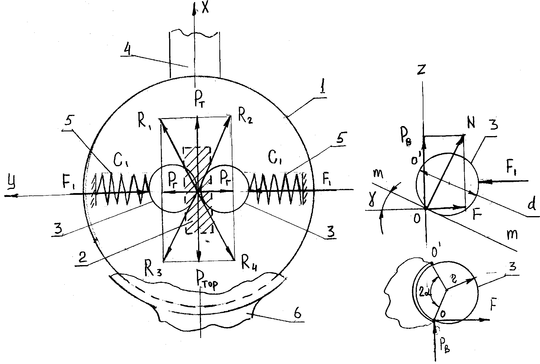 | Figure 11. Design scheme |
As the initial data, as in the previous cases, the following numerical values of design loads: Ркр(max) = 850 N, and Pm = 2500 N and Ртор = 1175 N(see formula 1).To calculate the strength of the stop trapezoidal 2 (Figure 10 and Figure 11) on the strength of the cross section in contact with the rolling elements 3of the clamp, where the vertical component of the force applied PB tending to break its Р. Experimental studies in the field of fixation in it any tensile stress loading towing devices cars show that the vertical components of the dynamic loads on the connecting fingers on average, with a probability of less than 0,1, does not exceed 20% of the longitudinal components of efforts manifested in the breakaway torque train with places and therefore, in this case value PB can be taken to be 500 N. It is also constructively taking the geometric dimensions of the connecting abutment trapezoidal section 2 having an average rectangular size: a = 20.0 mm and b = 7.0 mm, wherein the rolling body is located 3 of the clamp d = 8 mm, calculate the tensile stress in this section, depending on: As a material for [р] = 200 MPa according to GOST 1050-88.the stop trapezoidal steel choose 45. The result shows that the strength condition is satisfied. Since the vertical component of the PB attached to the palm of trapezoidal shape, can reach a value of 500 N, then from its action on the ball there normal N and radial components of F (Fig. 11). Both of these forces tend to overcome the force of the compressed spring stiffness C1 and such strength can be determined from the dependence:
 .In this case it is clear that there was to deformation of the spring must be satisfied F ≥ N or Pв ≥ Ntgα, where α angle coverage hole stop trapezoidal 2 3 rolling body retainer selected constructive and equal 380. Using reference data chosen the following geometric characteristics of the spring under load its ability 645 N: Dнар= 15.0 mm, wire diameter 3.5 mm, length 18.0 mm spring, stiffness Спр = 45 N / mm, Material Steel 60S2 with τ = 570 N/mm2.It should also be noted that the denial of coupling can occur when the spring 5 (Fig. 11) is fully compressed and under the influence of the maximum load PВ сhance slice of rolling elements in their cross-section. The diameter of the cross section in the plane selected 5.2 mm, and then the shear stresses in this section to determine:
 It can be seen that the allowable stress [τ]for steelШХ15, which made their rolling elements for bearings, 14.8 times higher than the calculated value. Consequently, in this case, the strength condition is satisfied and unhooking car and trailer completely excluded.Analyzing the above it is clear that in practice in the preparation of lightweight trucks trailers can be as different in design and have different weights and lifting performance, and on this basis, in order to enhance the operational capabilities of the proposed device, in each case must be installed on trailers its towing device designed according to the weight of trailers and their destination. At the same time for the selection of a rational design of a wide range of required testing of specimens in the operating conditions, and only after that you can finally justify their optimum geometrical characteristics.
4. Results of the Study
Based on the foregoing, the following conclusions and suggestions.1. Analysis of both domestic and foreign designs towing devices lightweight trains shows that the latter have significant drawbacks in terms of operations on their service in the tractive connection. So, first of all, such an operation is labor-intensive, requires a series of consecutive concerted action and the best thing is that all parts of the device described in the end keyed manually. It is known that, without paying sufficient attention to the procedures tractive connection, as a result the driver may forget to install the cotter pin, or the last, due to a lack of divorce him fixing parts may subsequently spontaneously fall out and then the consequences unhooking units train in motion can be very serious, injury until people were fatal. Given the above as inventions (RU2230675, RU2397881, RU2493996, RU2397883, RU2290322, RU2493974) devices developed technical solutions to simplify the operation of the car tractive connection and lightweight trailer and ensure a secure connection to the past conditions.2. To establish a rational geometric and kinematic parameters of some of these devices are designed numerical schemes and calculations for their justification. Thus, the calculations as applied to lightweight train consisting of VAZ2107 VAZ2109 and cargo trailer with MSW- 81021 have shown that stresses in the various parts of the proposed constructions trailer hitch devices are generally not high and do not exceed the permissible values that can make conclusion about the safe operation of trains lightweight and reliability of the technical solutions regulated OST37.01.096 -77 and GOST 4.396-88 for cars.3. Results of the study are recommended for domestic and foreign transport companies, automobile industry, science and engineering departments working in the automotive industry for the study and analysis of the proposed designs for possible further put them into practice.
References
| [1] | Melik-Sarkisyan A.S., Vinokurov V.Y. Trailers for passenger cars. - Moscow: Transport, 1999. – 79 p. |
| [2] | Vysotsky M.S. etc. Car and trailers. - M.: Mashgiz, 1992. - 161 p. |
| [3] | Orlov P.I. Design Basics: Reference Manual. In 2 books. Prince 1/Pod ed. P.N. Uchaeva. - Ed. 3rd, rev. – M.: Mechanical Engineering, 1988. – 560 p. |
| [4] | Gilyarovskaya L.T., Endovitsky D.A. Financial and investment analysis and audit of commercial organizations. – Voronezh, Voronezh State University Publishing House, 1997. – 336 p. |
| [5] | Shchukin M.M. Hitches cars and tractors. Leningrad: Mashgiz. 1996. – 230 p. |
| [6] | Ponomarev S.D., Andreeva L.E. Calculation of the elastic elements of machines and devices. - M.: Mechanical Engineering, 1997. - 326 p. |
| [7] | Short automotive guides. 10th ed .rev .and add. - Moscow: Transport, 1983. - 220 p. |
| [8] | Zakin Ya.Kh. Road trains, vehicle design development, Proceedings of us, no. 12. Mashgiz 1995. – 351 p. |
| [9] | Chudakov E.A. Theory car. M.: Mashgiz. 1985. - 272 p. |
| [10] | Theory and design of the car. Tutorial for motor colleges / V.A. Illarionov, etc. - M.: Engineering, 1985. - 368 p. |
| [11] | Smirnov G.A. Theory of the motion of wheeled vehicles. Textbookfor mechanical engineering students specials universities - 2nd ed., ext. and rev. - M.: Mechanical Engineering, 1990. - 352 p. |
| [12] | ZakinYa.Kh. Applied theory of train movement. M.: Transport 1987. - 215 p. |
| [13] | Slivinskij E.V., Zaitsev A.A. Increase traffic safety devices trains. Monthly theoretical and scientific journal Automotive Mashinostroyeniye, № 12, 2006. - 31 p. |
| [14] | Faronov V.V. Delphi. Programming in high level language. - St. Petersburg.: Peter, 2004. – 75 p. |
| [15] | Slivinskij E.V., Zaitsev A.A. Improving the design of devices and components of automotive trains: monograph. - Elec: YSU I.A. Bunin, 2009. – 236 p. |
| [16] | Maintenance manual, operation and maintenance of the VAZ -1111, VAZ -11113 "Oka" Kozlov P., Volgin S., Kosarev S., Ed.: AST Astrel, AST Publishing Group in 2004. - 174 p. |
| [17] | Tutorial by Device car. Yakovlev V.F.Ed. Third Rome.2008. – 80 p. |
| [18] | Theory car. Elements of calculation of technical and operational properties of the car. Dyakov I.F.Ed. UlSTU, Ulyanovsk. 2002. – 185 p. |
 Abstract
 Reference
 Full-Text PDF
 Full-text HTML