Slivinsky E. V., Kiselyov V. I., Radin S. Y., Mitina T. E.
Yelets state university of I.A. Bunin, Moscow university of means of communication (MIIT)
Correspondence to: Slivinsky E. V., Yelets state university of I.A. Bunin, Moscow university of means of communication (MIIT).
| Email: |  |
Copyright © 2014 Scientific & Academic Publishing. All Rights Reserved.
Abstract
In the present article the materials, concerning are provided to the description of perspective constructions of the devices intended for increase of coefficient of coupling of wheels of industrial locomotives with rails and increase by that of their tractive characteristics. The purposes and research problems and based on the analysis of the numerous domestic and foreign literary and patent sources devoted to this problem are justified, the devices increasing pulling force of locomotives are offered at the level of inventions, calculation procedures Are offered, physical and mathematical models by determination of the key geometrical and kinematic parameters of the above constructions are developed. The key geometrical parameters of a row of the offered constructions which are recognized by inventions are calculated. Development it is recommended to research and development and industrial structures in the field of railway transport for the purpose of their further study and possible implementation in practice.
Keywords:
Wheel couple, Railway line, Coupling coefficient, Rolling circle, Wheel crest, Magnetic induction
Cite this paper: Slivinsky E. V., Kiselyov V. I., Radin S. Y., Mitina T. E., To the Question of Increase of Pulling Force of Industrial Locomotives, International Journal of Traffic and Transportation Engineering, Vol. 3 No. 2, 2014, pp. 107-118. doi: 10.5923/j.ijtte.20140302.07.
1. Introduction
It is known [1-5] that different types of locomotives are widely applied to support of transportation process on railway transport and in the industry now. Depending on a type of primary power source the modern locomotives divide on thermal and electrical. Engines of general use which are exploited on the country railroads by the nature of operations divide on trunk (cargo, passenger and the universal) and shunting, and those locomotives which are used by the industrial enterprises for transportations on intra factory ways, timber loggings, in mines, etc., carry to the industrial. The kind of operation of the locomotive defines a choice of its key tractive parameters (power, pulling force, motion speed, etc.) and the main constructive forms and the sizes (an axial formula, diameter of wheels, etc.). Despite rather high performance of the modern locomotives, last, for a number of reasons, are still far to perfection. Essential lack of all known types and models of locomotives is that in case of their start-off from a place under train or overcoming of curves of small radius and limiting rises there is a danger of skidding of wheels of wheel couples, and such danger is watched in case of their movement in way curves, overcoming of rises, etc. For elimination of a slipping of wheels or their skidding at the time of braking on greasy or wet rails the modern locomotives are supplied with sand systems. However and last possess the shortcoming, being that their maintenance promotes littering of railroad tracks, sand hit in kinematic couples of different mechanisms and nodes of locomotives that leads in raised their wear, appearance of different failures, etc. Especially such shortcomings are characteristic for industrial locomotives, for example, such models widely used in our country as TEM2U, TGM6A, TGM12, TGM8E, TGM4A, TGM14, TGM23V, TGM40, TGM61 and TU7A. It is known also that railway lines where are used industrial railway transport, differ radically from trunk on the quality and therefore last and in particular industrial locomotives have low reliability of the running gears.For the solution of the task directed on reliability augmentation of running gears of industrial locomotives, today there are two main most important the directions it, first, lowering of a skid of their wheels due to development the anti skid of protection of the microprocessor devices based on use working without involvement of the driver [3] allowing to provide increase of potential coefficient of coupling on all types of locomotives and, secondly, devices raising adhesive force of a wheel with a rail due to use of mechanical devices allowing to increase frictional force at the expense of a static load by a wheel or uses of methods of mechanical input in contact of a rail and a wheel of elements raising frictional force in this zone.
2. Research Objective
Considering the above, in EGU of I. A. Bunin throughout a row of years chair of Application-oriented mechanics and an engineering graphics together with chair Locomotives and locomotive economy of MIIT, researches on subject of YuVZhD coordinated with Control RZhD branch of JSC and Yelets separation of YuVZhD are conducted. One of the directions of such NIR is development of the technical funds allocated for increase of tractive abilities of industrial locomotives. The analysis of numerous bibliographic sources, and also domestic and foreign patents (SU1063638A, SU115952A, SU1728073A, SU1217706A, SU1058816A, SU1341086A, DE4125885A1, WO9415801A1, US4431227, GB1560256, etc.) allowed to develop technical solutions recognized inventions (A.S No. 1341086, A.S No. 1728073, A.S No. 1063638, A.S No. 1058816, A.S No. 1115952, RU2247661S1 and RU2246406C1) allowing in a certain level to increase coefficient of coupling of wheels with rails and consequently to increase tractive ability of industrial locomotives in different modes of their movement. Considering such features, descriptions of such constructions, with reasons for a row of their geometrical and kinematic parameters allowed to give some assessment of operability of the last are given below.
3. Research Technique
It is known [1-5] that tractive calculations are area of application-oriented mechanics and pursue the practical aims of the solution of tasks connected to train movement on the basis of the general laws of the theoretical mechanics, specially delivered tractive tests of locomotives and experience of driving of trains in operational conditions.The active force created by the propulsion system of the locomotive by means of the rails, enclosed to wheel center about and rotating a wheel round a point of O1 of its contact with a rail is called as pulling force. We will consider the diagram of forces operating on a wheel (fig. 1). In a point of a contact of a wheel with O1 rail the horizontal force of O1F1 applied from a wheel to a rail, causes, according to the law of action and reaction horizontal response of O1F2 from a rail to a wheel and equal to O1F1 force. In this case force of OF1 applied to an axis of a wheel, appears external force in relation to the locomotive. This force causes wheel rotation concerning O1 point as the instantaneous center of turn and by that promotes locomotive progress therefore this force call a driving force. On a rim of a wheel force of OF1 and force of O1F2 which, as we know, significantly depends on a vertical component of an axle load of wheel couple, that is the more own mass of the locomotive is called as pull force not, the its tractive ability is higher. Though this force also doesn't "pull" the locomotive, but is obviously external in relation to it and the prime cause of origin of a driving force of OF. For such locomotives as locomotives and electric locomotives as a result can be written pulling force of the Fk locomotive in a look where, M – the given moment on a wheel from the tractive electromotor.
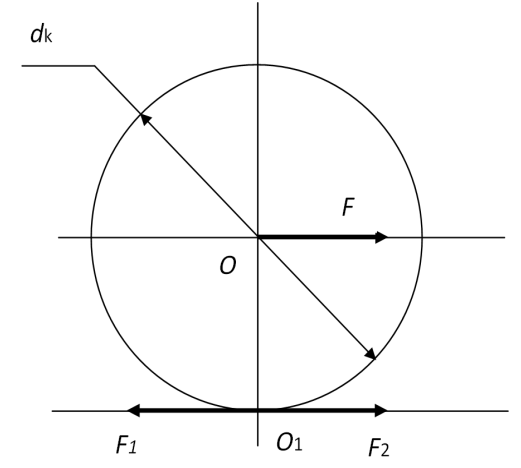 | Figure 1. Estimated diagram |
Considering the above and in particular, that pulling force significantly depends on a vertical component of the loading attached to an axis of wheel couple and friction coefficient in a contact zone a wheel rail, we will consider a row of the technical solutions developed by us and the first of them A.S No. 1341086 it is shown in fig. 2 bound to wheel couple, for example, TEM2U locomotive with its section on AA.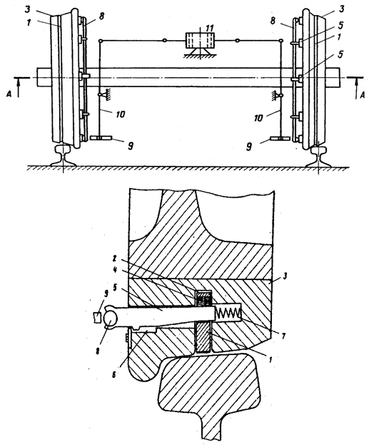 | Figure 2. The upgraded wheel couple |
The device contains the compound ring 1 set in ring bore 2 bandages of 3 and 4 rather maple pushers 5 sprung by springs, 6 compound rings 1 placed in holes sprung by springs of 7 concerning a bandage 3 and connected to ring 8, interacting with the push roller 9, and last is connected via the double-arm lever 10 to the force cylinder 11, mounted on a locomotive frame. Operation of the device happens as follows. In case of a slipping of wheel couple in an automatic mode oblate air in the force cylinder 1 and its rods moves turn double-arm levers 10 pressing rollers 9 to rings 8 which move together with maple pushers 5. And maple pushers 5 advance compound rings 1 out of limits of surfaces of rolling of bandages 3, as promotes increase in coupling of wheels of the locomotive with rails. After the slipping of wheel couples will stop the force cylinder 11 also automatically is disconnected also maple pushers 5, and also rings 1 under the influence of springs 7 and 4 return to home position.It is visible that in the proposed technical solution the most loaded its constructional element is the compound ring of 1 (fig. 2) which shall provide reliable service of the loading arising from action of effort created maple pushers 5, on a horizontal surface of a head of a rail. As a first approximation, considering that such device can be used in construction, for example, a shunting locomotive of TEM2U, we will read that unit pressure arising between a ring and a surface of a rail shall be at least loading of equal p = 60 N/cm2, an outside and inside diameter of a ring Dн = 840 mm and Dв = 800 mm, and the estimated radius ofr = 210 mm are respectively equal. We will read also that the specified ring is the symmetric jacket h thickness = 15 mm and 18 mm wide, and the area of contact of a maple pusher 5 with a ring 1 is equal 5,0cm2. Using a known calculation procedure [8] and the estimated diagram of fig. 3 we will calculate tension arising in a ring in that case when it under the influence of the loading created by a maple pusher of 5 (fig. 1), is drawn in to a rail head.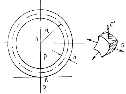 | Figure 3. Estimated diagram |
We read that in our case the ring is the symmetric jacket and tension in it can be determined by the moment less cornerstone at the heart of which the ratio called by Laplace equation and in particular on a formula when the tension is biaxial is and has an appearance: .The carried-out calculations showed that if the ring is executed from alloy structural steel 40HFA in accordance with GOST 19282 – 79 with [σ] = 486 MPa, it corresponds to the given durability, as value of tension σ1 = σ2 = 420 MPa that is less than allowed value [σ] = 486 MPaby 1,15 times.A little similar technical solution is described in A.S by No. 1063638 and shown in fig. 4. Such wheel couple of locomotive consists of an axis 1 on which wheel centers 2 with a circle of rolling 3 and crests 4 are rigidly fixed. In crests 4 there are cross open holes 5 in which blocks 6 are movably placed supplied on the one hand a notch 7, and with other a circular ring of 8 9 placed 10 crests sprung by springs in deaf holes 4. Wheel centers 2 are located on rails 11 with which blocks 6 interact. Rings 8 also interact with persistent rollers 12 which are movably located on the levers 13 hingedset on the casing of bearings 14, set on an axis 1. Levers 13 hingedare connected to a rod 15 and the casing of the pneumatic cylinder 16 which has been movably set on a frame of the cart 17 of the locomotive.
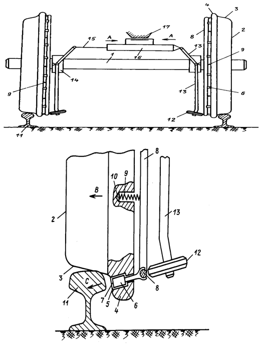 | Figure 4. The device according to the patent SU1063638 |
Operation of such device consists in the following. In case of the steady or accelerated movement of the engine of a detail of wheel couple are in the situation shown in fig. 4. In the same case when wheels 2 wheel couples slips, in technique give a known method pressure to a pneumatic cylinder 16, thus it and its rod 15 move on arrows A (fig. 4), turning levers 13 and pressing thereby persistent rollers 12 to circular rings 8, and they in turn, deforming springs 9 on an arrow B (fig. 4) the blocks which were only from below 6 on an arrow C advance pressing them to a lateral surface of a head of a rail 11. As blocks 6 have a notch on the edge surface, last create reliable contact of awheel2 with a rail 11. After disappearance of a slips of wheels the 2nd pressure in a pneumatic cylinder 16 remove and under the influence of springs the 9th blocks 6 enter holes of 5 crests 4, returning in home position of pull 13 with persistent rollers 12.And one more technical solution (A.S No. 1115952) also based on use of a row of details of wheels of wheel couples of industrial locomotives entering construction.So in fig. 5 the general view of such device is shown.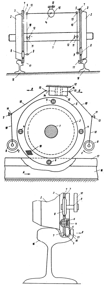 | Figure 5. The device according to the patent SU1115952 |
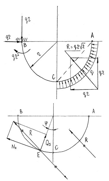
In this case the provided device consists of an axis 1 on which wheels 2 with crests 3 are rigidly fixed. Mobile crests 5 are connected to wheels 2 by means of bolts 4, and in between and bolts 4 located dish-shaped springs 6. Fixed crests 3 and mobile crests 5 are supplied with chamfers 7 which contact to the conical rollers 8 which have been movably set on axes 9 of levers 10. Last by means of hinges 11 are fixed on a frame of the 12th locomotive, and their ends by means of other hinges 13 are connected to rods of 14 pneumatic cylinders 15 which are also fixed on a frame 12. Wheels 2 are located on rails 16 supplied with a counter rail 17, оn edge part of a mobile crest there is a notch 18.Operation of such device is that in case of need increases of tractive ability of the locomotive, mobile crests 5 under the influence of the conical rollers 8 which have been movably set on axes 9 of levers 10, move in the axial direction concerning an axis of 1 wheel couple and contact with counter rails 17 increasing thereby frictional force in kinematic couple "wheel rail".The described construction can be used not only for increase in pull of the industrial locomotive at the expense of a mobile crest of a wheel drawn in to a counter rail by a pneumatic cylinder, but also for its braking when the effort created on brake shoes by the main brake can be insufficient.Analyzing the described constructions it is visible that, first, they are quite difficult on the device due to existence of levers, the springs, controlling elements in the form of clamping rolls, open and not open channels executed around crests, use arail with directing crests, etc., and, secondly, application of sliding elements interacting with heads a rail which will be in practice subject to the considerable transverse loads capable is residual to deform them that in a consequence will affect working capacity, both their drive, and the wheel of wheel couple as a whole. Simpler construction from above considered is the development described in A.S No. 1058816. So in fig. 6 the section of part of a wheel of the industrial locomotive before interaction of an elastic ring with the additional rail set on that section of a way where origin slips its wheels is possible and during its interaction with an additional rail is shown.This device comprises a resilient ring 1 with a notch 2, covering crest 3 of bandage 4 wheels 5 of wheel set of locomotive. To keep the ring 1 on the wheel 5 stops 6 are mounted on the side surface thereof. The elastic ring 1 interacts with an additional rail 7.The device works as follows. On a way section where it is necessary to create the raised towing capacity set an additional rail of 7 tracks located in internal part with the smooth congresses 9. Elastic ring 1, being moved on a rail 7, as a result holds such position which allows it 2 to contact the notch with a head of a rail 8, and it allows to increase adhesive force of wheels with rails. After pass by a locomotive of the above section of a way and absence of an additional rail 2 elastic ring returns to home position.Analyzing such technical solution, it is visible that the elastic ring 1 works under trying conditions, thus it is elastic is deformed in case of contact with an additional rail of 7 (fig. 6) that promotes origin in it normal stresses, and also with a head of the main rail where tangent tension is shown. We will execute calculation of such tension, using a known technique [9], reading that the part of an elastic ring interacting with the specified rails can be provided in the form of a bar with the curvilinear axis and, its axes of symmetry of sections lie in the force plane. In this case beams a having ratio of r/h≥ 5, where by r the radius of curvature of an axis of a bar, and h the cross size of section are usually considered. Forces and the moments of forces being transmitted through the area of the considered section of a curve bar are determined by rules of mechanics by a coercion way to the center of gravity of section of external forces and pairs of forces operating on a bar on one side of section. On the estimated diagram of fig. 7 the part of an elastic ring which on a section the AC is loaded with a uniform load of q arising from his interaction with specified rails (fig. 6) and from an emphasis of 6 of its seals on a bandage of 4 wheels is shown.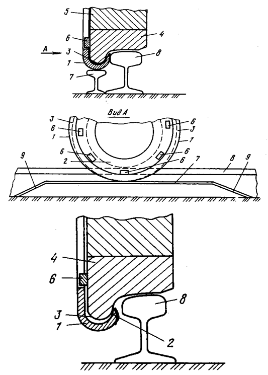 | Figure 6. The device according to the patent SU1058816 |
 | Figure 7. Estimated diagram |
For such curve bar of small curvature loaded on a section AC q uniformly distributed load within intervals the AC and CB in case of 0 ≤φ≤π/2 it is possible to write for interval AC the following analytical expressions for Nх, Qy and Mz:
 ,
,  .For CB interval in case of π/2 ≤φ≤π we will lead equally effective R to the considered section of a point of E bars and then for this section also for Nx, Qy and Mz we will receive the following expressions:
 ,
,  ,
, .Having defined the above loadings it is possible to calculate the normal, tangent and equivalent tension arising in an elastic ring on known formulas [8]:
 ,
,  ,
, For calculation of such tension, in case of use of the proposed technical solution in construction, for example, a shunting locomotive of TEM2 [10], we will accept the following basic data - a material of an elastic ring 1 spring steel 50 HGFA in accordance with GOST 4543-79 with σв = 1422 MPa, q = 800 N/cm, the area of a contact zone F = 3,25 cm2, the moment of resistance of section of a contact zone, Wz= 1,3 cm3, its axial moment of Sz = 3,9 cm3, and its axial inertia moment of Jx = 1,63 сm4, height of a section of a contact zone h = 2,5 cm, the radius of curvature of an elastic ring of r = 2,2 cm, equally effective effort made an elastic ring from R rail = 2000 N. Having carried out conversion of formulas (1) which have an appearance (see. window of the program of fig. 8) and using the Mathcad computer program complex diagrams (fig. 9) characterizing change normal σ= f (φ), tangent τ = f (φ) and the equivalent σэкв = f (φ) tension arising in an elastic ring (fig. 7) in its different sections are constructed.
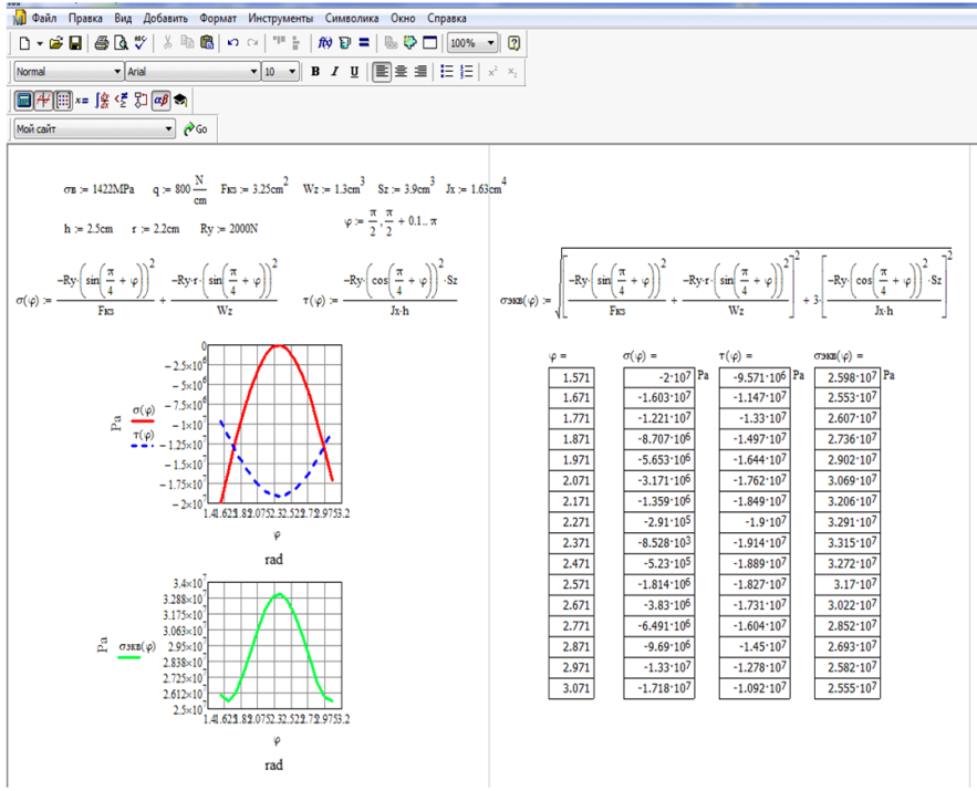 | Figure 8. Example of a window of the program for computation of tension |
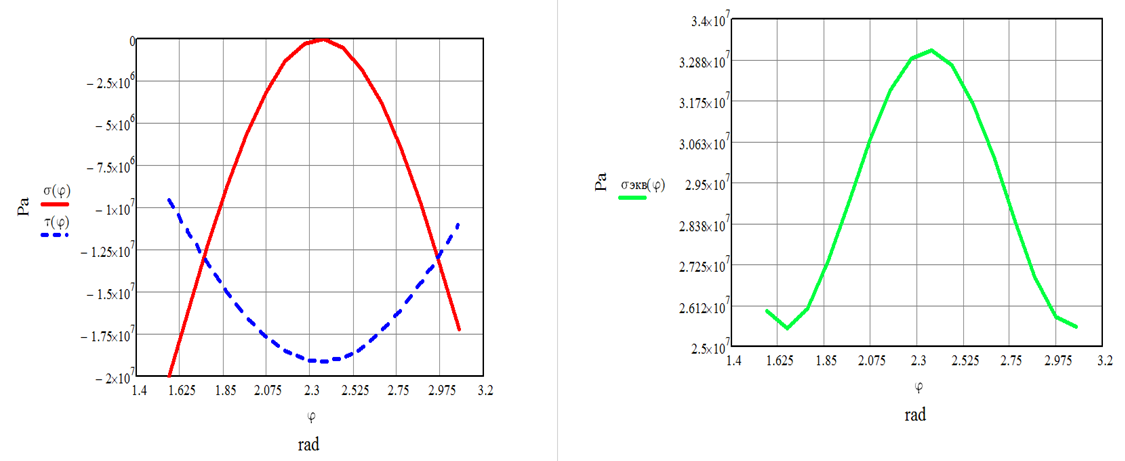 | Figure 9. Diagrams of change of tension in sections of an elastic ring |
Analyzing the received diagrams it is visible that the maximum values of normal stresses σ arise in the section of an elastic ring in case of φ = 2,32 is glad and are equal σ = 280 MPa that below allowed value [σ] = 980 MPa. Tangent tension also low and their maximum value makes τ = 187 MPa that also below allowed [τ] = 245 MPa. The equivalent normal stresses are slightly higher and are equal σ = 335 MPa, but all the same they are lower than allowed values. Therefore it is possible to draw an output on operability of the proposed technical solution as durability of an elastic ring apparently is provided. However, for a final assessment of operability of the described device it is necessary to carry out its broad tests as in bench, and the experimental conditions.We will consider one more technical solution (RU2247661) also representing wheel couple of industrial locomotive (fig. 10) which operation happens as follows.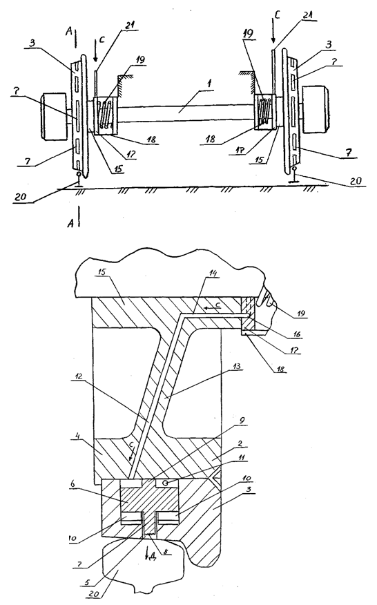 | Figure 10. The device according to the patent RU2247661 |
At the time of start-off from a place, the driver, at the same time with supply submission on tractive electromotors of the locomotive widely known methods in technique, in a manual or automatic mode, gives oblate air to the pipelines which flow arrives to the circle canal of an axial fixed emphasis, getting from it to the horizontal canal, then to the radial channels 12 executed at wheel center of 2 wheels (fig. 10). These channels are connected to cavities of notches 11 and therefore under the influence of its pressure the plunzher who were in them 9 move and, is elastic deforming flat springs of compression 10, quit notches of hooks 7 on insignificant distance of an order the 5-7th. As the wheel couple starts rotating, each of hooks 7 will be able to contact with a rail 20, and because of existence of notches by them 8 increases adhesive force of a wheel with a rail. It is necessary to mark that when each of hooks 7 will enter a zone of contact of a bandage with a surface of a head of a rail, it to be drowned back in a notch in the direction opposite overcoming the effort created by oblate air on a plunzher, but, despite it his notch will adjoin all the same to a head of a rail and, therefore, to create conditions on coupling of a wheel with a rail. As soon as the locomotive which is under train will receive steady movement, air supply in pipelines stopand under the influence of elastic forces of flat springs of compression 10 plunzher 9 returnto home position. Further the described process can repeatedly repeat. The device described in this patent can be widely used in constructions of industrial locomotives, for example, the TGM3A, TGM13V, TGK2 types, etc.We will consider now the device which excludes from the construction the constructional elements directed on creation of frictional forces in between and rails which is also recognized by A.S's invention No. 1728073 (fig. 11).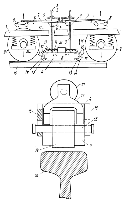 | Figure 11. The device according to the patent SU1728073 |
In this case on a frame of 1 locomotive by means of compression springs 2 and pull 3 boots 4 of the magnetorail brake are suspended. Pull 3 are supplied with the emphasis 5, 6 double-arm of the levers 7 contacting to forks which ends bear on themselves the reference skating rinks 8 interacting with wheels of the 9th cart 1. On boots 4 solenoids 10 in which the rods 11 hinged associated to turning fists 12, also hinged fixed to boots 4 are movably placed are set. The ends of fists 12 interact with the axes 13 bearing full-turning rollers 14, movably placed in directing 15 boots 4. Rollers 14, boots 4 and wheels 9 contact to a rail 16, and fists 12 are sprung by compression springs 17 concerning solenoids 10.In case of start-off from a place widely known methods in technique give a supply to a boot 4 of the electromagnetic brake that creates conditions on relocation it on an arrow B in the direction of a rail 16. Thus the 16th boot can't adjoin to a rail because full-turning rollers 14, appearing for a boot 4 surface a little, will rest against a rail 16. At the same time with boot 4 relocation on an arrow B will move in the same direction and pull 3 which the emphasis 5 turn double-arm levers 7 on an arrow C. It promotes that reference skating rinks 8 with the considerable effort will nestle on wheels 9 which will in turn be drawn in to a rail 16 on arrows D. Such subpress of wheels 9 to a rail 16 will provide increase of effort of coupling of a wheel with a rail. At the same time with it give a supply to tractive electromotors of the cart of the locomotive that promotes its steady progress. After a set the engine of a certain motion speed a supply of a boot of the magnetorail brake 4 stop, and it returns to home position together with reference skating rinks 8shown in fig.9. In case of locomotive braking at the same time with supply submission to a boot 4 it is magnetic the rail brake give a supply and on the solenoid 10 which turns on arrows T fists 12 together with turning rollers 14 providing that full contiguity of a boot 4 to a rail and by that to creation of brake effort.It is known [7] that attracting force of a boot of the electromagnetic brake being function from the contact area  ,
, in case of a constant magnetic flux
  and magnetic conductivity
  , and it can be determined by a formula:
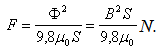 We will give an example of calculation of attracting force of a boot to a rail in case of the following basic data:
  - boot width (
 ),
), - boot length (
 ),
),  (width of a head of a rail of P75),
  - induction in a working gap between a boot and a rail (
 ) and
) and  - magnetic conductivity of air gap
 , then surface
  area of contact of a boot with a rail will be:
 In this case the effort of an attraction
  of a boot to a rail will be defined:
 If to read that, for example, on a shunting locomotive of TEM2 supplied with two three-axis maxillary carts it is possible to set eight magnetorail brakes of the carts located between wheel couples that as a result it is possible to receive additional loading falling on wheels of wheel couples in the amount of FΣ = 0,251∙8 = 2,008 т. Such loading will allow to increase tractive ability of a locomotive and by that to reduce probability of a slipping of its wheel couples.The "Calculation of Attracting Force of EMRT" program was developed for execution of calculations for different models of industrial locomotives in the Delphi language, allowing to determine on them a rational number of magnetorail brakes. And the last technical solution also recognized the invention (RU2246406) which represents wheel couple consisting of an axis 1, and on it rigidly fixed wheel centers 2 with right 3 and with the left 4th ring of a bandage (fig. 12). Right ring 3 are integrally formed with curved fingers 5, offsets in response holes 6, end surfaces 7which riveted. Between end faces of rings of a bandage 3 and 4 on the one hand the air gap 8 is executed, and with another in a similar gap the diamagnetic ring 9 is placed. The right ring of a bandage 3 is supplied with a crest 10, and on his curvilinear fingers 5 induction coils 11 connected by conductors with collector rings of 12 1 wheel couples set on an axis are located, and through brushes 13 they have electrical communication with a source of a direct current of the locomotive.
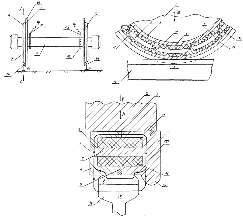 | Figure 12. The device according to the patent RU2246406 |
At the time of locomotive start-off from a place, on slip rings 12 give direct current voltage from an available source located on the locomotive. Construction of a slip ring 12 such is that happens connection of only one induction coil 11 being in a zone of contact of a wheel to a rail 14 to a network which in a magnetic conductor will create a magnetic flux. Such magnetic flux will cause force of a magnetic attraction N applied from a wheel to a rail which allows to increase a static load, by wheel couples transferred to rails. In case of further turn of the wheel, the specified coil 11 quits a zone of its layout with a rail, and its supply stops, but the following coil 11, having entered the specified zone, receives a supply and also as well as in the previous case creates magnetic force of N. Further the described process can repeatedly repeats.In our opinion for industrial locomotives the last device is more perspective and therefore for carrying out calculations for establishment of the additional thrust load created by magnetic force, arising from supply submission on coils, and also pulling forces of the locomotive at the time of its start-off from a place and movement, the estimated diagram shown in fig. 13 is developed.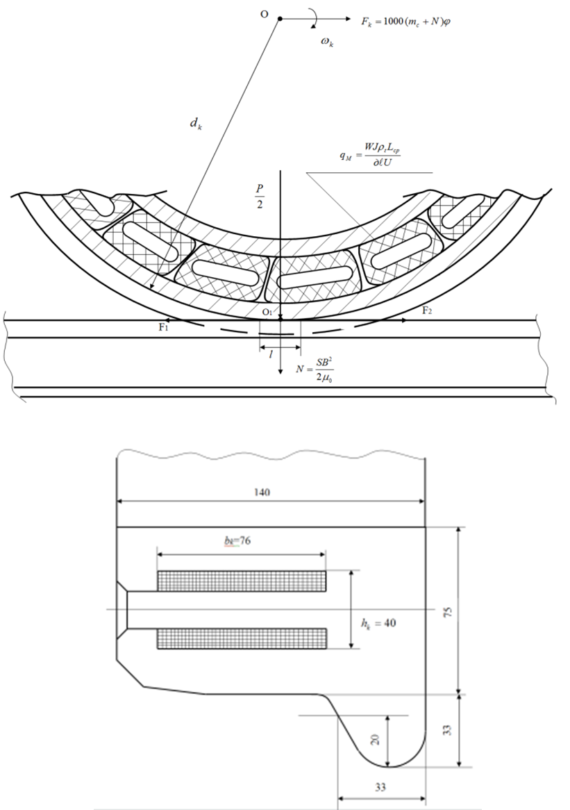 | Figure 13. Estimated diagram |
The last represents a wheel of wheel dk with a diameter of couples locomotives to which the thrust load of P/2 created by its official mass of mc is attached. In O1 point, from action of forces of a magnetic attraction by the created electromagnetic coil with number of rounds of W, the additional force of N will be applied. In case of wheel rotation with angular speed ω there is a tangent pulling force of Fk which on value will be equal to the horizontal force of F1, and also F2 force. We read that the wheel of wheel couple contacts to a rail on a site of long l, and, using a known method of calculation of magnetic circuits, we will determine the magnetizing force of the coil WI=Nk necessary for creation of additional attracting force N wheels to a rail on a formula written above: where, B – induction in a work space between a wheel and a rail, T;μ0 – magnetic conductivity in air gap, Gn/m;S – the area of contact of a wheel with a rail
  .We will make calculation, for example, for a shunting locomotive of TEM2U with the axial characteristic
  which official mass makes mc= 120т and the axle load is equal 20,0т. We will accept also value B = 2Тл,
  Gn/m and the area of contact of a wheel with S rail = lb = 0.85∙0,75 = 0,64
  , where b width of a head of a rail of P75, and l length of contact part of a wheel with a rail of equal 85 mm. Then:
 It is visible that on one wheel of wheel couple of locomotive of TEM2 it is possible to receive the additional force of 1,01 t that makes about 10% of a static load of
  t. Then on all 12 wheels (6 wheel couples) locomotive an additional vertical component load of wheels will make N12=1,01∙12=12,2t. It is known that tangent pulling force of a locomotive of TEM2 in case of the long mode of movement is equal to
  , therefore, with use of a proposed technical solution pulling force in case of movement of a locomotive will make:
 where, ψ – the coefficient of coupling of a wheel with a rail and for locomotives is equal in movement 0,24.From the given calculation it is visible that tangent pulling force
  >
> ; and I increased in a movement mode approximately by 1,5 times.In case of start-off from a place
 where, ψ – the coupling coefficient in case of start-off from a place is equal 0,3. Proceeding from the geometrical sizes of a bandage of a wheel of wheel couple of locomotive of TEM2, it is constructive we will set overall dimensions of one bk coil = 76 mm, hk = 40 mm, lk = 125 mm. For determination like a winding wire of the coil and its section, we will be set by coil I current = 20A, number of its rounds of W = 100 pieces, the given tension of U on it = 50V, and as value of unit resistance, which for a copper wire equally in
  Om∙sm.We use a known formula for determination of section of a winding wire [6]:
 where,
  - average length of a round of the coil of equal 330 mm;χ – the dimensionless coefficient equal 0,1 [6].
 -unit resistance of a material of a wire in case of calculated temperature of the heated coil in the set mode and equal 2,0 [6].According to GOST 7019-71 we select brand of a wire of the design and estimate documentation which section is equal 1,25×3,53 mm. Considering that diameter of a wheel of a locomotive is equal to dk = 1050 mm, and the coil is on diameter of 900 mm, we will define number of coils set on one bandage of a wheel
 pieces.The technique of execution of calculations is developed for automation of carrying out calculations for establishment of optimum design data of the proposed technical solution on a computer with Delphi language use.
4. Results of Research
Results of research are recommended to the industrial enterprises exploiting and making the rolling stock, as in our country, and abroad for the study, the proposed technical solutions and possible further their implementations in practice. It is confirmed by that, first, the proposed technical solutions are created at the level of a row of inventions (A.S by No. 1341086, A.S No. 1728073, A.S No. 1063638, A.S No. 1058816, A.S No. 1115952, RU2247661S1 and RU2246406C1) and have no analogs in world practice.Secondly, on the example of No. 1341086 patent Ampere-second the carried-out calculations showed that if the ring located in a wheel of wheel couple is executed from alloy structural steel 40HFA in accordance with GOST 19282 – 79 with [σ] = 486 MPa, it corresponds to the given durability, as value of tension σ1 = σ2 = 420 MPa that is less than allowed value [σ] = 486 MPa by 1,15 times.In the third, the calculations which have been carried out for construction of the device, executed according to A.S No. 1058816, showed that the maximum values of normal stresses σ arise in the section of an elastic ring in case of φ = 2,32 is glad and are equal σ = 280 MPa that below allowed value [σ] = 980 MPa. Tangent tension also low and their maximum value makes τ = 187 MPa that also below allowed [τ] = 245 MPa. The equivalent normal stresses are slightly higher and are equal σ = 335 MPa, but all the same they are lower than allowed values. Therefore it is possible to draw an output on operability of the proposed technical solution as durability of an elastic ring apparently is provided. However, for a final assessment of operability of the described device it is necessary to carry out its broad tests as in bench, and the experimental conditions.In the fourth, the considered perspective technical solution according to A.S No. 1728073 which, for example, can be used on a shunting locomotive of TEM2 supplied with two three-axis maxillary carts where it is possible to set eight magnetorail brakes of the carts located between wheel couples that as a result can receive additional loading falling on wheels of wheel couples in the amount of FΣ = 0,251∙8 = 2,008 m. Such loading will allow to increase tractive ability of a locomotive and by that to reduce probability of a slipping of its wheel couples. The "Calculation of Attracting Force of EMRT" program was developed for execution of calculations for different models of industrial locomotives in the Delphi language, allowing to determine on them a rational number of magnetorail brakes.And the fifth, last technical solution also recognized the invention (RU2246406) in our opinion is more perspective and therefore proceeding from the geometrical sizes of a bandage of a wheel of wheel couple of locomotive of TEM2, is constructive overall dimensions of one coil respectively equal bk = 76mm, by hk = 40mm, lk = 125mm areset, and also is defined like a winding wire of the coil and its section, in case of such parameters as coil I current = 20A, number of its rounds of W = 100pieces, U tension = 50V, and as by value of unit resistance, which for a copper wire equally in  Om/sm. According to GOST 7019-71 the brand of a wire of the design and estimate documentation which section is equal 1,25×3,53 to mm is selected. Considering that diameter of a wheel of a locomotive is equal to dk = 1050 mm, and the coil is on diameter of 900 mm, the number of coils set on one bandage of a wheel is equal 22 pieces.The technique of execution of calculations is developed for automation of carrying out calculations for establishment of optimum design data of the proposed technical solution on a computer with Delphi language use. The considered constructions of devices directed on exceptions of a skid of wheels of locomotives it is recommended to the research and development organizations entering into JSC RZhD, and also the domestic and foreign structures which are engaged in creation, maintenance and repair of industrial locomotives and electric locomotives.
References
| [1] | Babichkov A.M. Egorchenko V. F. Tyaga of trains. – M.: Transzheldorizdat, 1947, 123 pages. |
| [2] | To Samma G. V. Frictional interaction of wheel couples of locomotive with rails: Monograph. – M.: Route, 2005, - 80 pages. |
| [3] | Minov D. K. Increase of tractive properties of electric locomotives and locomotives with electrical transmission. – M.: Transport, 1965, 163 pages. |
| [4] | LuzhnovYu.M. Coupling of wheels with rails. – M.: Intex, 2003, 82 pages. |
| [5] | Pokrovsky S. V., Logins I.Ya. Naumov B. M., Vikulin of E. New electronic protection against a skid and the skidding for VL85 and VL65 electric locomotives//the Locomotive, 1993. No. 5. |
| [6] | Kasatkin M. V., etc. Electrical engineering.Izd-e the 4th, reslave. – M.: Science, - 1983 - 104с. |
| [7] | L.V. bulb electromagnetic rail brakes. – M.: Transport, 1979 – 104p. |
| [8] | Resistanceofmaterials. Feodosyev V. I. Izd-vo Science, 1970, 544 pages. |
| [9] | Glushkov G. S., Sindeev V.A. Kurs of resistance of materials. M.: The higher school. 1965 - 467 pages. |
| [10] | TEM2 locomotive: The manual on maintenance and to software maintenance "Bryansk engineering plant ". Prod. the 2nd, reslave. and additional — M.: Transport, 1983 — 239 pages. |
| [11] | Construction calculation and design of locomotives. The textbook for students of higher education institutions.A.A. Kamayev, etc.Under.Edition of A.A. Kamayev. M.: Mechanical engineering, 1981. – 123p. |
| [12] | Construction and dynamics of locomotives. Under the editorship of V. N. Ivanov, 2е prod. additional M.: Transport, 1974. – 254p. |
| [13] | Danilov V. N. Track and its interaction with a rolling stock. M.: Transport, 1961. – 93p. |
| [14] | Locomotives. Construction, theory and calculation.Under the editorship of N. I. Panov.M.: Mechanicalengineering, 1973. – 186p. |
| [15] | Bromberg E.M. etc. Interaction of a way and rolling stock.M.: Transzheldorizdat, 1956. 96p. |
| [16] | NovachukYa.A. Nikitin D. N., Koblov R. V., Grigorenko V. G. Innovative simulation of speed of interaction of wheels with rails. XXІ engines of eyelids. Collection of materials of the International scientific and technical conference, the devoted to the 110 anniversary since birth Dr.Sci.Tech., professor E.Ya. Gakel.LIIZhT, St. Petersburg, 2013 – 172p. |
| [17] | Research of dynamics of locomotives. / S. M. Golubyatnikov, L.K. Dobrynin, A.I. Kokorev, etc. – Tr. VNITI, 1967, release 30, page 281 – 332. |
| [18] | Queens S.M., Dobrynin L.K. Avramenko V. S. Dynamic loads on the tractive electromotor in operational conditions. – Mechanical engineering /NIIINFORMTYaZhMAShtransitem, 1977, release. 14, page 35-38. |
| [19] | VA flats. Rotating oscillations of wheel couples of the locomotives, arising in case of a slip. – Тр. VNITI, 1966, release 22. |
 Abstract
 Reference
 Full-Text PDF
 Full-text HTML