E. V. Slivinskii, A. A. Zaytsev, S. Y. Radin, A. N. Puzatykh
I. A. Bunin Yelets State University
Correspondence to: E. V. Slivinskii, I. A. Bunin Yelets State University.
| Email: |  |
Copyright © 2014 Scientific & Academic Publishing. All Rights Reserved.
Abstract
In the article we set forth the results of scientific and research work carried out in I.A. Bunin Yelets State University in the field of maintenance of main and auxiliary railway tracks, which are used in the system of OJSC “Russian Railways”. We developed design models which allow to carry out analytical research of oscillations and force loading of working elements of the means of small-scale mechanization, created at the level of inventions for removing wild-growing vegetation on slopes and areas of railroad bed. We carried out numerical calculations of constructional elements of the offered technical solutions using a program complex on the computer for the substantiation of their geometrical and kinematic rational parameters. We developed practical recommendations for increasing productivity of works when maintaining and repairing railway tracks. The results of this work are recommended to research and industrial institutions both domestic and foreign ones, in the field of mechanical engineering for the purpose of their further studying and possible introduction into practice.
Keywords:
Cutterbar, Colter, Stem, Rigidity, Mowing machine/mower, Rotor, Disk, Elastic deformation, Kinetic energy, Crane, Electromagnet
Cite this paper: E. V. Slivinskii, A. A. Zaytsev, S. Y. Radin, A. N. Puzatykh, To the Question of Increasing the Production Efficiency of Preventive Works While Removing Wild-Growing Vegetation from Constructional Elements of Railroad Bed, International Journal of Traffic and Transportation Engineering, Vol. 3 No. 2, 2014, pp. 65-82. doi: 10.5923/j.ijtte.20140302.04.
1. Introduction
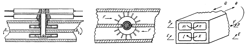
It is known [3, 7, 8] that in agricultural production various machines for preparing forage became widespread. The movable operating element of these machines is a cutterbar. The operation of such operating elements is based on a retaining or non-retaining principle of shear. To the group of cutterbars of retaining shear belong segmental fingerbar and non-fingerbar mowers in which the stem of the plant, when cutting,leans on a fixed anti-cutting element of the machine. To the group of cutterbars of non-retaining shear belong rotary-disk and rotary-drum machines. In figure 1 two types of mowers equipped with such devices are shown. This segmental fingerbar consists of a comb 7 and a colter 14, executing reciprocal motion. When shearing stems there are forces pressing the colter to the comb. The runner fixes internal and external shoes on the ends of the comb. The shoes allow to control the height of the cut of the plant. The motion of the colter, which lies within the range from 76,2mm to 101,6mm, is an important technical feature of such a mower. The cutting of plant stems by segmental fingerbar machine is realized on the model of scissors, and the colters are put into motion by the slider-crank mechanism, that is why its speed of motion changes continuously. The speed of cutting units lies within the range from 2,7 to 2,8 m/s.The other mower is equipped with a rotary-disk cutterbar, consisting of a rod with movable disks which have colters. Their peripheral speed is 40-60 m/s. In this case the colters cut stems of plants with a stroke. The bend of stems is limited by their rigidity, inertia and partial backing-up of neighboring stems. The advantage of such mechanisms is their ability to operate at high forward speeds providing qualitative shear of plants. In practice, the above-mentioned mechanisms are used on mounted or pull-type mowers mainly matched with wheeled tractors. In the first type of mowers the cutterbaris attached to the frame of the mower by the pull rod, which allows to tilt the comb forward or backward. The mechanism is actuated by the cardan shaft of the tractor with the help of an eccentric pulley and the V-belt drive, covered with a case, and by the shaft with a leading pulley. The second type of mowers – rotary mowers, used for cutting high plants – became most widely spread. They are used for improving grasslands, overgrown with small bushes and weeds. The cutterbar of such a mower consists of a rod at the top of which there are rotors with colters, and the latter, rotating towards each other with a frequency of about 2000 min-1, qualitatively cut stems, basing on a non-retaining principle of shear. A significant drawback of described mowers is their constant cutting width – 2.1 m. Recently, for increasing the cutting width and changing it as necessary depending on the working space, the Production and Technical Department of SDDT-Evromash (Belarus) has been producing a mounted rotary mower KRD-1,5, which is fixed on the wheeled tractor MTZ 80/82 YK. Using folding mechanism, this mower can mow steep and deep slopes, cut snow planting screens, etc. Taking it into account such mowers are often used during preventative works while removing wild-growing vegetation from elements of the railroad bed. However, as of today they have not been used widely, so manual labour is widely used when doing such kind of work. 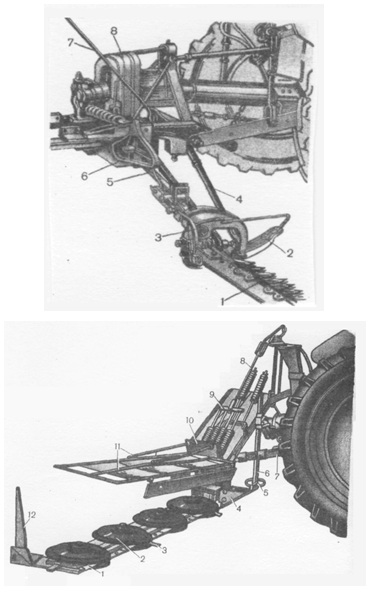 | Figure 1. Types of mowers with different cutterbars |
In 2002, a self-propelled rail vehicle was produced in Yelets Branch of Yugo-Vostochnaya Railway (Southeastern Railway). It included a trolley and a platform on which there was a serial rotary mower – model KRN-2,1, actuated by a hydraulic drive, placed on the latter one. This vehicle ensures the removal of wild vegetation, but its efficiency was low due to the complexity of control (one person ran the trolley and the other one controlled the mower standing on the platform) and limited width of working surface coverage.It is known that in the above-described arrangements are currently not fully used in the practice of removing wild vegetation in the summer time and the majority of such work is performed manually, which significantly affects the labor and material costs IF services of "Russian Railways". At the same time, such works are mainly engaged in the brigade, consisting of women, and their complexity significantly affects their health. Therefore the use of the above techniques to date is very important.Analysing the above-mentioned facts, it is clear that the use of well-known design of mowers in processing elements of a railway track profile for removing wild-growing vegetation is often impossible, as the latter one has different steepness of embankment, varying over a wide range of micro and macro profile of their surface, etc. In these cases, tractors with mowers of mentioned models can not process track sections. At the same time, attaching them to the railway rolling stock units (we wrote about in above)does not give positive effect, because the width of coverage of serial mowers does not exceed 2,1 m, and, therefore, it is impossible to process the embankment slope.
2. Aim and Objectives of the Research
Taking into account the above-mentioned, the aim and objectives of this research are:1. To develop prospective technical solutions which will ensure the efficiency of removal of wild-growing vegetation, firstly, from large areas of railway elements, secondly, allowing to copy micro and macro roughness of the embankment and adjoining sections. 2. To develop design and mathematical models for calculating main rational kinematic and geometric parameters of the proposed design. 3. To develop computer programs aimed at performing automated calculations for establishing stated parameters.
3. Research Methodology
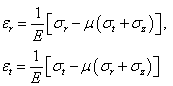
It is known [12-14] that in practice they use various methods for determining both kinematic, and dynamic parameters of cutting unites of mowing mechanisms. To determine them it is necessary, first of all, to know the rigidity of stems and branches when bending them, while they are interacting with rotor colters. To do it we can use, for example, the following dependence [10]: | (1) |
where Q - is the given mass of the stem, kg;l- is the length of the stem, m; T- is the period of stem oscillation under the load, s.Varietal peculiarities of plants significantly affect the rigidity of stems and branches. It is also established that the rigidity of stems considerably depends on the humidity, and when it goes down, the rigidity increases sharply [10]. It was stated earlier that the rotor colters during rotation cut stems of plants by means of the impact load appearing in the contact area. It is known that the impact is characterized not so much by the law of force variation P(t), as by the integral value - impact momentum [12]: where
where  the time of impact start and end. Due to the fact the process of collision is characterized by the value change (t1 – t0), then in that case the value of S is called instantaneous impact momentum, and we can write:
 where δ – is Dirac delta function.As a result, also knowing the own mass of the cutting stem m1and the mass of the colterm2, maximum force P(t) resulting from the impact, we can define the dependence:
 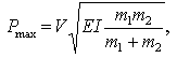 | (2) |
where V - is the peripheral speed of the colter, m/s;EI- is the rigidity of the cutting plant Н∙mm2.Using certain parameters Pmax and EI we can calculate the stress in the sections of the colter according to the known dependence: | (3) |
where l – is the length of the colter, mm.If we consider the colter of a rotary mower as a rod with a rigidly bedding-in end, the strength calculation is based on the solution of transverse oscillation equations which are studied in the theory of oscillations [13,14]. In this case, it is assumed that the deviation of points of the rod axis during transverse oscillations is definitely determined by the function of two variables  . This function meets the linear differential equation in partial derivatives of the fourth order:
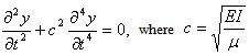 | (4) |
This equation is derived on the basis of Ostrogradskiy- Hamilton’s functional, made by the most general conditions relative to the forces influencing the rod (colter), rigidity and weight distribution. Doing a series of transformations and solving the obtained equation by the Laplace transform, we get desired equations.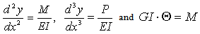 | (5) |
They allow to calculate normal σ and tangential τ stress in sections of the rod (colter) and in future to select their rational geometric characteristics. The final step in designing rotary-disc mower mechanisms is the problem of determining stresses arising in disks themselves, as they are fast-rotating. If we consider the rotary disk of a constant thickness h then the easiest way to determine stresses in the disk is to apply the D'Alember principle, and to introduce inertial loads, distributed about the disk volume, as external forces [13,14]. For the volume element  inertial force equals the product of mass
  and normal acceleration
  , which can be written as:
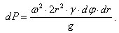 | (6) |
As a result, projecting forces on the direction of disk radius r, we obtain the equation of this kind: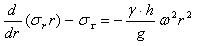 | (7) |
Integrating this equation, we determine the stress σr and στ.Over the last few years, due to the creation of new structural materials, rotary mowers with cutting elements made of various flexible ties, called pins, became widely used.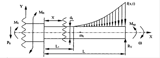 | Figure 2. Design model of the pin |
When a rotary mower works elastic pins, interacting with the vegetation, constantly experience elastic deformations that cause fatigue stresses in different sections of the pins and their places of incorporation. At the same time elastic pins make complex spatial oscillation. Taking into account such a feature of the work of elastic pins, the design model of their force loading (Fig. 2) was created and analytical research to determine stresses in them was conducted.When developing a design model the following assumptions were made:1. We assume that the localized mass of the pin  is located in its center of gravity; 2. We disregard the influence of axial and transverse oscillations of the rotor bearings on pins; 3. We assume that the elastic axis of the pinisrectilinear and coincides with the line of the center of gravity of its section;4. We disregard the gyroscopic effect of the rotating rotor; 5. We believe that the deviation of points of the pin axis occurs at the time of transverse oscillations in the same plane and is insignificant.The design model consists of a given mass
  and the moment of inertia
  . The cutting element (pin) of diameter
 and length
  is loaded with distributed load
  with a period of its change
  , as well as dynamic components arising from the removal of wild-growing vegetation, concentrated force
  , bending moment
  and torque moment
  . Since the rotor disk, to which the cutting element is attached, rotates with frequency ω, then the distributed load from the influence of shearing vegetation can be written as
  , and the intensity of the moment load
 , respectively. It is clear that
  = 0 when
  where n = 0,1,2,…. Since transverse oscillations of the elastic pin occur in two mutually transverse planes, the calculation scheme in such cases is the same. However, in the process of changing the density of vegetation distribution along the length of the processed area, the amount of distributed load
  will change due to the force of impact of the load
  and torque moment
  . Therefore, to simplify the task we will be seeking the solution for the oscillations of the elastic pinonly in one plane ХОУ. It was noted in the assumptions that the elastic axis of the pin is rectilinear and coincides with the line of the centers of gravity of its cross-sections, then the OX-axis can be regarded as coordinate and we can calculate from it the deviations of elements of the considered rod under its transverse oscillations [14]. Then such oscillations are determined by a single function with two variables
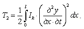
  . This function meets the differential equation of the fourth order, which can be easily derived. Analyzing the design model, it is clear that the kinetic energy of the oscillating pin will be comprised of the kinetic energy of transverse displacements of the elements of pin sections
  and the rotational kinetic energy of these elements around the axes perpendicular to the plane of oscillation. In this case, using basic propositions of the theory of oscillations [14] we can state that:
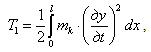 | (8) |
 | (9) |
At the same time, the potential energy  for to rsional elastic deformation of the pin and the potential energy
  under transverse load
  can also be written as:
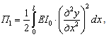 | (10) |
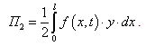 | (11) |
Knowing the values of the kinetic and the potential energies of the system Ostrogradskiy-Hamilton’s functional can be written as: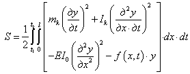 | (12) |
Using Euler equation [13] we can write an equation describing transverse oscillation of the elastic pin: 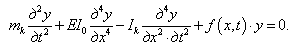 | (13) |
Let us solve equation 13 using a well-known method of superposition of small oscillations supposing that such oscillations of the system with an infinite number of degrees of freedom present a linear position of main harmonic oscillations in time: | (14) |
where  is the function defining a persistent set of amplitudes of deviations of the centers of gravity of elastic pin cross sections from the equilibrium position along its length. Inserting equation 14 into equation 13 and having transformed it, we get the following equation:
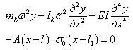 | (15) |
Let us solve equation 15 by the Laplace transform [13], designating the correspondence between the image of the unknown function and its original in the form: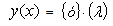 | (16) |
Then equation 15 will take the following form: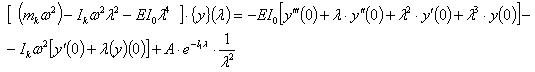 | (17) |
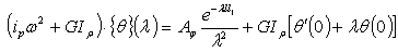
Due to the fact that the design model considers the pin as a rod with a built-in end, at the other end of which the external force Rу and the moment Мкр are applied, then in this case the following boundary conditions will be true: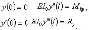 | (18) |
Using equations 18 and 17, the expression, to picture the desired solution, will be written as: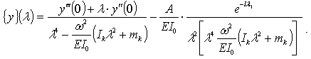 | (19) |
Returning to the original, we will get the value of the deflection of the elastic pin using the table of inverse Laplace transform in the following form: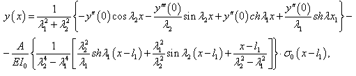 | (20) |
where: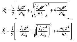 For the analysis of torsional oscillations of the elastic pinletusdenote its to rsional stiffness as
  where
where  is the polar moment of inertia of the cross-section of the pin. Here let us imagine the moment load
  as intensive load. Then the intensity of the external moment load at the pin part can be represented as follows:
 | (21) |
In this case Ostrogradskiy-Hamilton’s functional has the following form: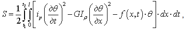 | (22) |
where  -is a running (distributed) moment of the pin section inertia relative to its longitudinal axis;
  - isangle strain of the elastic pin section. The necessary extremum equation of this functional (according to the Euler equation) can be written as:
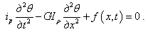 | (23) |
The solution of this equation we find in this form: 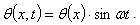 Then for the case of pin bending equation 23 will be written as follows:
 | (24) |
Solving equation 24 using the Laplace transform, we will obtain the following expression for the image  of the desired function
  :
: | (25) |
Choosing the boundary conditions in form of 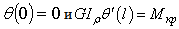 we will get the following equation:
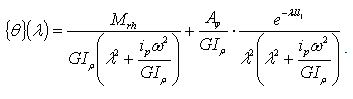 | (26) |
Letusdenote  and then, using the table of inverse Laplace transform, we will find angular displacement of the elastic pin by the formula:
 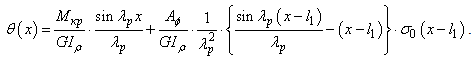 | (27) |
To determine stresses arising in sections of the elastic pin along its length, we use the known relations [12]: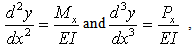 then the second and the third derivatives by
  can be written as:
 | (28) |
 | (29) |
To find  and
and  we use the following equations:
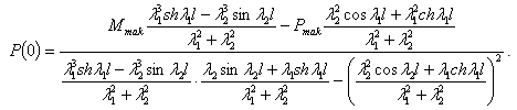
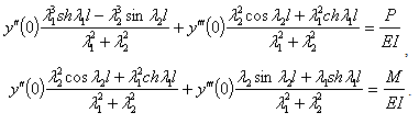 | (30) |
Solving such equations, we obtain the values of  and
and  arising in the place of elastic pinbedding-inon the disk of the rotor of the rotary mower, depending on the maximum loads
  and
and  by dependencies:
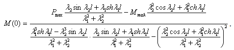 | (31) |
 | (32) |
Having calculated  and
and  , normal stresses in the bedding-in of the pin can be determined by the known dependence [12]:
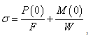 where F- is the area of the cross-section of the elastic pin;W -is the moment of resistance of the elastic pin section.To determine the shearing stresses arising in the bedding-in of the elastic pin under the influence of
  , we use the condition
  , then taking the derivative of equation 27 we obtain:
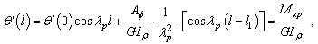 | (33) |
 | (34) |
Having calculated  , shearing stresses can be calculated by the dependence:
  We now consider a number of prospective structures and calculate their main geometric and kinematic parameters.
3.1. Development of the Device According to the Patent RU2243145
Thus, the analysis of multiple bibliographic sources, as well as domestic and foreign patents allowed to develop a number of technical solutions which were recognize as inventions that allow to solve the assigned task connected with the removal of wild vegetation from profile elements of the railway track in spring and summer time. Basic technical solution (RU2243145) is shown in Figure 3 and represents a railway crane on the suspension bracket of which there is a rotary mower. To remove wild vegetation on the designated site of works, the crane is placed the way, for example, as it is shown in Figure 3. After that the crane operator applies power to electric motor that brings rotors and their colters into motion cutting stems of wild-growing plants. Once the rotors are put into rotation, the crane operator brings the drums of the slusher into motion and the latter, reeling steel ropes on itself, moves the mower along arrow A of the embankment slope. It also allows to cutwild-growing vegetation. While moving the crane operator lifts and lowers the crane hook block according to arrow B, driving the crane arm according to arrow C. Since the embankment slope of the path has uneven microrelief abundant of hollows, juts, and so on, then in such cases the orientation of the mower is carried out using the slusher. This allows to place the mower at different angles to the longitudinal axis of the railway track, thereby allowing it to adapt effectively to the micro profile of the slope and remove wild-growing vegetation.Despite the described effect, the proposed suspension bracket of the rotary mower still does not provide the qualitative removal of wild-growing vegetation because the serial rotary mower, which is used in this design, having the coverage width of 2.1 m and a rigid bar, does not allow to copy the microrelief of the processed surface.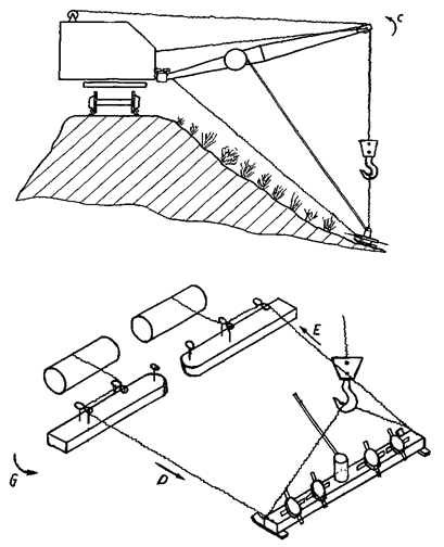 | Figure 3. Mechanism according to patentRU2243145 |
It is known that in design and operation of hoisting machines an essential condition of their effective use is the creation and application of universal hauling devices. It allows, firstly, to reduce their amount and range, and, secondly, to increase their efficiency in the production of various cargo operations. With this in mind, we have created a universal mounted mechanism for the railway crane. It was also recognized as an invention (RU2243142, RU2243143) made on the basis of lifting electromagnets. Firstly, due to high self-weight of lifting electromagnet, which averages from 1,3 to 4,9 t, it allows to ensure sustainable balance and efficient movement in space and, secondly, due to the feed circuit connected to its coils we can successfully solve issues associated with the development of energy of mechanisms which are mounted on it and intended for cutting wild-growing vegetation. The first solution according to patent RU2243142 is a lifting electromagnet (Fig. 4), which has an electric motor on its body. On the shaft of the electricmotor there is a rigidly fixed compression spring which is also rigidly connected to the disk that has movable colters. When working the disc and the colters are recessed by the electromagnet into its cavity, and using it as a mower, they supply power to the electric motor, and due to centrifugal forces the colters go beyond the disk limits and cut wild-growing vegetation. The analysis of such a design shows that its most crucial element which the reliability and the efficiency of work depend on, is a helical compression spring. To establish its geometric and strength properties, and thus its performance under operating conditions, let us do the following calculations in respect to the electromagnets M42B type of maximum capacity  , its own weight G=1500 kg, the maximum diameter of the body DFR=1170mm, the height of the body HFR=290mm and the diameter of the central hole in the body Dh=130 mm. As a turntable drive with colters let us take an asynchronous electric motor with short-circuited rotor of 4AM80V2U3 typ e having a capacity of Pel=2,2kW with a nominal torque moment Tel=7,5H m and shaft speed nel=2850 min-1. We also believe that the operating force, influencing the spring when pressing it, and required for a reliable hold of the disc with colters is
  [10,11]. Taking the spring index as
  and the coefficient considering curvature of turns
  [19], we define the diameter of the spring coil according to the dependence:
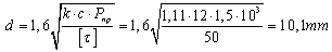 According to GOST 9389-70 we once and for all accept the diameter of the spring coil as d=10mm. Then the outer diameter of the spring Dsp will be 120mm. We will choose the height of the spring H on the basis of structural considerations. It will consist of an electromagnet height HFR =290mm and a clearance formed between the bottom of the electromagnet body and disc colters H3=100mm, i.e. H=Hfr+H3=290+100=390mm. Spring ends both from the electric motor and from the disk with colters, are screwed onto the threaded bedding-ins of l=50mm each. Taking into account this feature, as well as recommendations for the design of helical compression springs [19], we define stresses in coils of the spring at the following types of its loading:1. From the action of the torque Tel occurring on the shaft of the electric motor, there occurs an elastic torsion of the spring relative to its longitudinal axis of symmetry. It is known [19] that at small angles of lifting of helical spring coilsa bending moment occurs, which can be taken as Tel, then:
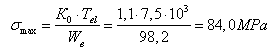 where Wв-is the moment of resistance of the coil section
 -is the coefficient which depends on the section shape and curvature of the coil, 1,1 [45].Since for spring steel 60С2, which spring
  is made of [19], then in our case
  is 15 times less than
  , hence the strength condition for this type of loading is met.2. When the disc with colters contacts wild-growing vegetation and micro and macro profile of the processed surface, there occurs both pure and cross bending of the spring in the vertical plane. In the first case, according to the theory of greatest shearing stresses without the curvature of the coil, the equivalent stress can be determined according to the dependence:
  where Mn- is the moment which bends the coil of the spring in the tangential plane, that goes through the cross section of the coil placed at an angle
  to its horizontal axis:
  where
where  is the average value of the force applied from wild-growing vegetation to the disk with colters [19].
 - is the moment which bends the coil of the spring in its transverse plane and depends on both the angle
  and the angle
  of the incline of the coil to the horizon
 .In this case we can also see that the obtained value
  is 35 times less than
  , so its long durability is secured. In the second case, normal stresses at the points of section periphery in the plane of the bending moment also eliminating curvature of the coil are determined according to the known dependence [18]:
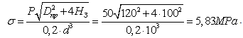 It is much less than
  In the operation of the described mechanism with a certain axial load on the spring, it can lose its stability and therefore in such cases in practice with sufficiently large ratio of its height to the average diameter, we calculate the critical force
 , but since the latter is almost entirely located in the through hole of the body of the lifting electromagnet then there is no need to do these calculations.Despite the simplicity of the design the described mechanism has a significant drawback. When using a lifting electromagnet as a hauling device in processing metal-roll, metal shavings, old metal, etc., its disc with colters, whenever you change the polarity in coils of the electromagnet, will constantly "deviate" from the body forming as mentioned above a clearance of 100mm. This, in turn, if the crane operator is inattentive, can lead to a residual deformation of the disc with colters in the collision with overloaded metal load.
3.2. Design and Substantiation of Rationale Parameters of the Universal Handling Devices Patent RU2243142, RU2243143
So, the most effective, in our opinion, is the design made according to patent RU2243143C1, which eliminates the above-mentioned drawback. This design represents (Figure 4.) the lifting magnet itself , consisting of a round body with a central through hole and electrical coils consecutively connected to an alternating current source, such as, a railway crane, a trolley or another rail vehicle. In the central through hole there is a cage rotor, the lower part of which is rigidly connected to the disk which is interconnected with the body through the rolling elements, while the upper part is also connected with it, but through the thrust bearing. 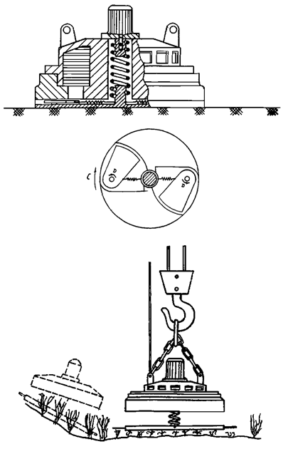 | Figure 4. Mechanism according to patent RU2243142 |
The disc itself is provided with radial ducts of cylindrical form. They have flexors which are placed with a clearance and a possibility of reciprocal motion. The flexors, for example, are pieces of a steel rope, one end of which by means of stress spring is fastened to the disk, and the other ones are recessed into mentioned radial ducts. It is possible to connect electromagnet coils to the current source both consecutively (when the lifting electromagnet is used for processing steel products or old metal) and according to the "star" scheme. It will allow the electromagnet coils to work for creating a rotating magnetic field necessary for rotating the rotor with a disk, and thus to use it as a rotary mower for cutting wild-growing vegetation (Fig. 5). | Figure 5. Mechanism according to patentRU2243143 |
Using the design model presented above (Fig. 2) and the corresponding equations we calculated normal  and shearing stresses
  for the two types of pins. We believe that the pins are made of pieces of steel and nylon ropes rigidly fixed on the disc of the lifting electromagnet, here with we use the following values: length of the pin l = 350 mm, ω = 305-345 с-1,Естали = 2,1·105МPа, Екапр.. = 18,0·104МPа, Gстали = 8·104МPа, Gкапр = 3,8·103МPа, mк.ст. = 0,130kg, mк.капр. = 0,073kg, dк = 10mm, Jρ = 0,018 cm4, Jx = 0,009 сm4, F = 0,7сm2, EJ = 75,26 до 609,1Н·mm2 (the rigidity of stems of wild-growing vegetation with their diameter from 3,5 to 8,0mm). Using the Delphi language we did a series of calculations on the computer to determine stresses in the places of bedding-in of elastic pins in different phases of the angular rotation of the rotary mower rotor, from going into the grass and bush mass of wild-growing vegetation to their withdrawal from the contact with it.The calculations showed that for the angular velocities set in the range ω = 305-345 s-1 with a pitch of 5.0 s-1 the average value of normal stresses for the two types of pins is19.4 MPa, and for shearing stresses is 4.8 MPa. At the same time, these same stresses are registered by experiments in the spring and summer time at the stage Yelets-Stanovoe of Yelets Branch of Yugo-Vostochnaya Railway (Southeastern Railway). Tests have shown that for both types of ropes in their interaction with truncated wild-growing vegetation at the working angles from 850 to 1350, with the speed of the disk 2945 rpm-1, normal stresses in their bedding-indo not exceed the values of σ = 30 MPa, and shearing stresses τ = 10.5 MPa, while safe values for the selected design of their fastening in the disk are653 MPa and 95 MPa. Therefore, the conditions of the strength are met, and the discrepancy between the calculated and experimental data respectively, for normal and shearing stress is about 10.6 MPa and 5.7 MPa.Analyzing the design of universal mechanisms made on the basis of lifting electromagnets we can see that the main load element in them is a rapidly rotating disk, which work is performed in difficult conditions and the latter one in operation can either obtain significant permanent deformations or collapse completely. To assess its strength and the choice of rational geometric characteristics let us consider the design model presented in Figure 6. We believe that the disc rotates with a constant angular velocity
  and its thickness
  is constant. The radius of the disc in this case is b. Let us single out an element on the surface of the disc in the shape of acurvilinear hexagonal with the volume
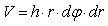 and the mass
 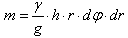 which the inertial force
  is applied to, where
  is normal acceleration equal to
  . The direction of this force will be opposite to the direction of normal
  acceleration, i.e. from the axis of the disc rotation to its periphery.
 | Figure 6. Design model of the disk |
It is known [13] that in the axial sections of the disk, by conditions of the axial symmetry, the shearing stresses are absent and only normal stresses  are saved (peripheral) while normal stresses at the end faces of the element are radial and indicated as
  . Using the basic equation of statics
  , let us find the sum of the projections of all forces in the direction of the radius
  whence
 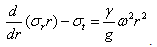 If the radial displacement of the element is denoted by
  and we use a known equation [13] of generalized Hooke's law in its volumetric loading where
  ,
, then as a result we can get the following equation:
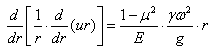 After double integration we obtain the following equation:
 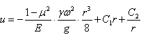 from which we can determine radial and circumferential stresses [20]:
 | (35) |
Since there is a radial stress  on the outer generatrix of the diskcontour, and on the second, inner contour, where, for example,
  it is less obvious, and in order to limit the displacements
  and stresses
  and
and  , it is necessary to have
  . Thus the only unknown quantity is
  , which can be determined if the stress, occurring on the external contour, is amounted to nothing [13]:
 Then expressions 35 will take the form [13]:
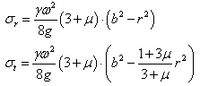 Taking into account the nature of distribution diagrams of stresses
  and
and  constructed for a rapidly rotating solid disc [13], we calculate their values based on its kinematic and geometric parameters in relation to the loading electromagnet M42B by the formulas: a) in the central part of the disk,
 where
where  is the density of the material of the disk (disk made of steel 45according to GOST 1050-74 with
  );
); - is the angular velocity of the disk,
  ;
; - is the Poisson's ratio,
  ;
; - is the free fall acceleration
  ;
; - is the disk radius.The given calculations show that numerical values of maximum stresses
  and
and  arising in the disk are low in comparison with
  and so its strength in operation will be ensured.
 | Figure 7. Mechanism according to patent (RU2242859) |
 | Figure 8. Design model |
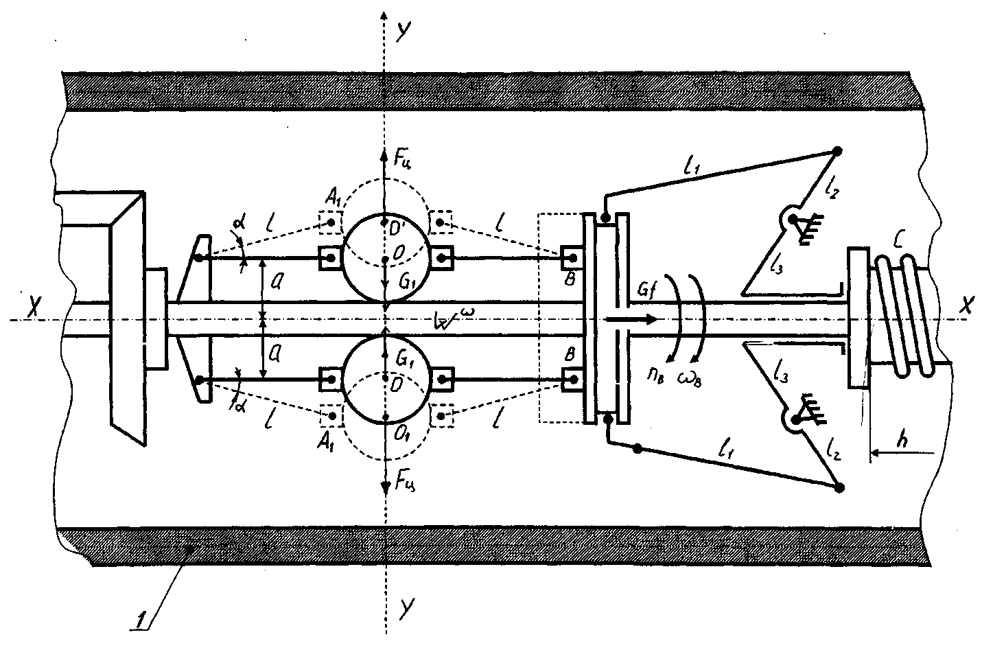
3.3. Development and Substantiation of Parameters to New Rotary Mowers Patent RU2242859, RU2239977
As indicated above it is possible to mountserially produced rotary mowers on the crane or another rail vehicle. The analysis of the performance of such mowers shows that the latter ones can not copy processed surfaces due to high longitudinal rigidity of their frames by torsion and therefore the use of the latter ones for cleaning railroad tracks is extremely limited.Taking into account this drawback, we have developed a prospective design of the rotary mower, eliminating the described drawback (RU2242859). This rotary mower (Fig. 7) is a P-shaped frame on which there is a number of hollow sections with rotors and colters mounted. The mower works this way. For cutting grass and wild-growing vegetation the mower is mounted on the processed area with a crane. Thereafter choosing the mowing mode, we set the speed of the rotors at about 1300 - 1500 min-1. In this case, the torque is passed from the drive to horizontal shafts of hollow sections, and through the conical pair it rotates the rotors, which contact with the vegetation by colters, and cut it. At a certain point in time (for example, when processing embankments and slopes of railways) micro and macro soil profile may change and therefore the crane operator, guided by the visual information of profile changes, increases the shaft speed, e.g., up to 2000 min- 1.Such increase in speed leads to the actuation of centrifugal governors, which loads under centrifugal forces move along arrows В, actuating the lever system. The latter ones influence the end faces of the necks of ball joints with flats and move them along arrow C, thereby squeezing the compression springs. Since the ball joints with flats are limited in axial direction of hollow sections by the end covers, the hollow sections are moved relative to each other along arrow C. In this case, each section relative to the next one receives three degrees of freedom (displacement along arrow C and D , as well as angular rotation according to the arrow E) , and thus individually adapts to the profile of the processed area, removing vegetation effectively. As soon as the micro and macro profile becomes even, the crane operator reduces the speed of the driveshaft. Centrifugal governors get back to their original position, the compression springs move the ball joints with flats and necks in the direction opposite to arrow C, conical fingers go into holes of adjacent hollow sections and the rotary mower sets into position, processing horizontal area.Analyzing this design of the rotary mower we can see that the rotors with colters and their mounting on therod does not differ from serial mower KRN -21, but the drive controlling component parts of therod (hollow sections) has undergone a significant change. Therefore, for studying the operation of the centrifugal governor and for determining its structural characteristics, as well as control elements of hollow sections relative to each other, we made a design model shown in Fig.8. On the design model balls with their own weight G1are installed with the help of levers l on the drive shaft rotating with angular velocity ωв. Levers with the length l are also connected with the coupling with weight Gby joints. The coupling with the help of rods l1 and two other onesl2 and l3 is sprung by a spring with the rigidity C relative to the hollow section. In the quiescent state, when ωв = 0 the angle α is also zero. When the shaft rotates at a predetermined angular velocity ωв ≠ 0 under centrifugal force Fц the balls move along the Y-axis, and their centers of gravity shift from points O to points O1, which are turned to the direction opposite to centripetal accelerations Wω. At the same time, the spring rigidity C at ωв = 0 is not deformed. Under forces Fц the coupling with the mass G together with joints weighing G1stand as shown in Figure 8 by the dotted line. It favours the creation of the axial force P due to angular rotation of double-arm levers with arms l2 and l3. This force allows to move hollow sections relative to each other along the X axis, resiliently deforming the spring with rigidity C. Let us consider the process of appearing of centrifugal forces Fц, when the arms l rotate through the angle α. In this case there will be a deformation (compression) of the spring C by the quantity h: | (36) |
So the force Pcan be determined by the dependence:  | (37) |
On the basis of the condition of uniform rotation of the governor when ω = const, we define the centrifugal force Fц by the formula [18]: | (38) |
where  is the distance from the centers of gravity of the balls to the axis of rotation of the governor XX.Let us consider a possible movement of the system in which the change of the angle α occured, given the change of the angular velocity (ω ≠ const). Let us set up a general equation of dynamics on the basis of the propositions of this work in the following way:
 | (39) |
Let us determine the coordinates of the points of application of forces in the selected coordinate system. The projections of possible displacements of these points we find by differentiating coordinates by the variable α:From the force G1: From the force G:xB= 2lcosα; δyB = - 2sinαδαFrom the force Fц:yA = -(a+lsinα); δyA = - lcosαδαyA1 = a+lsinα; δyA = lcosαδαWe insert the obtained displacements into equation 39 and convert it into equation
 | (40) |
Or let us write it in the following form: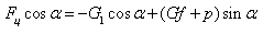 | (41) |
Inserting into equation 41the inertial force Fц (see equation 39) we finally obtain the equation: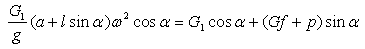 | (42) |
From this equation it is possible to find the value of the force P applied to the spring with rigidity C and, therefore, of the following hollow section of the mower by the dependence: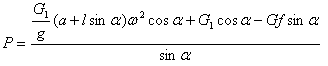 | (43) |
We perform numerical calculations of the force P on the following example. For structural reasons we assume that the spring travel is h = 100mm.It is necessary for the hollow sections 1of the rotary mower to move freely relative to each other in space. We also believe that the operating speed of the drive shaft of rotors (as well as in serial mowers KNR 2,1 ) is nB = 1200 min-1 (ωv =125,6s-1) and it works on a flat area of the processed surface . Simultaneously we choose the following basic initial parameters of the centrifugal governor:G1= 0.1 kg, а = 0,05m, l = 0,15m, α = 200, f = 0,15, G = 0,15 kg, g = 9,81 m/s2.With such values, using formula 43, we obtain: 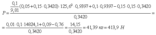 Now we consider that the mower meets macro roughness and the removal of wild-growing vegetation on them requires from the crane operator to create flexibility of the mower sections. To do ithe increases the rotational speed of the shaft 2 till the value nB = 1500 min-1 (ωв =157 s-1). Using the above-mentioned initial data we obtain that the force P in this case is:
 With such a value of the force P the spring will be fully elastically deformed and the value of its compression stroke, as indicated above, will be 100mm. We determine the spring rigidity by the following formula:
 | Figure 9. Mechanism according to patent RU2239977 |
For such spring rigidity according to tables [19] we determine its geometric characteristics such as: the diameter of the coil of the spring dB = 6mm, the outer diameter of the spring D = 45mm, the pitch t =12mm, the number of active coils n = 9, the total number of coils n = 11, the material of the spring Steel 60C2according to GOST 5047-56. Passing macro roughness of the profile of the processed area , the crane operator lowers the shaft speed 2 to nB = 1200 min-1 , and then under the influence of the spring the coupling G returns to its original position and hollow sections also under its influence again couple with each other as it is described above. Hereinafter described processes can be repeated several times.The described design of the rotary mower, despite its efficiency, also has a significant drawback – it is its essential complexity. Moreover, the drive itself during the operation because of shredded grass getting into its units and components will be apparently insufficiently reliable. So we offered another prospective design of the rotary mower which also recognized as an invention (RU2239977).This mower (Fig. 9) contains a rod with mounted rotors. Each rotor consists of two counter-rotating disks with colters. The upper disc is mounted on the shaft with solid section, and the lower disc is mounted on the hollow shaft. The shaft with solid section is movable in the hollow shaft, and at the bottom of each shaft there are blade wheels. The rod is divided into caves by a horizontal plate with vertically fastened partitions. Blade wheels are located in these divided caves, and the hollow caves are connected to the source of compressed air for creating a torque on the shafts. Disks with colters are rotated by the shafts and cut wild-growing vegetation. When contacting with extrinsic objects or more dense stems of plants there is a possibility of slip of rotor disks, which greatly increases the operational reliability of the mower. For studying the work process of the mower and for selecting its rational kinematic and geometric parameters, we developed a design model which allows to research the steady flow of the compressed air current and its interaction with blade wheels of the rotors in the space of the hollow rod by which the parameters of its state and its velocity at any point of the flow do not depend on time. As a mathematical model we use a well-known Euler equation describing the change in momentum of the gas flow [15]: where G - is gas mass flow per second;с1 and с2 - is the velocity of moving gas on the blade of the blade wheel.This equation allows us to determine the circumferential component of the force coming from the air flow which passes through the blades of the blade wheels of rotors of the mower according to the dependence:
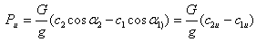 where с1u and c2u are circumferential components of the absolute velocity at the beginning and at the end of the blade of the blade wheel.It is known [15] that the angular momentum of the resultant force applied to the blades of the blade wheel makes the change of the total angular momentum, and on this basis the torque, developed by flowing air on the blades of the blade wheel, can be determined by the formula:
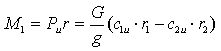 where r1 and r2 are a mean radius of the element at the inlet and the outlet of the flow of the compressed air from the blade wheel.Using main propositions of the source [15,16] and the above equations, we performed a series of calculations to establish a rational torque Ткр, arising on the blade wheel of the prospective rotary mower which is attached to a hoisting crane that is required to overcome the technological moment of resistance Тс produced by the cut vegetation with an average value of its flexural rigidity of about EJ= 0,11÷0,16 Н·mm. As the basic data we chose the following parameters: the receiver capacity available on the crane Vp= 123 liters, the air pressure in the pneumatic system of the crane p= 6,3÷7,5 kg/cm2;cross-sectional area of the hollow rod in the zone of the blades of the blade wheel of the rotor S = 0,0006 m2, the density of air at normal pressure, ρ= 1,29 kg/m3; dimensionless coefficient of compressed air in the cave of the hollow rod μ= 0,8÷1,0; gas constant of dry air 29,27 m/deg.; compressed air temperature Т=308÷323 К; an average radius of the blade wheel r= 0,085 mat the point of application of peripheral force Рл.Proceeding from this the amount of air consumption, passing through the blades of the blade wheel, its flow rate and the circumferential force applied to the latter, were determined by the known dependences [15]:
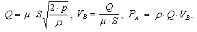 As a result of the calculations we found that at average values of compressed air consumption lying within the limits Q= 0,1m3/s, its velocity VВ= 183÷21 6 m/s and circumferential force generated on the blades of the blade wheels, Рл = 0,9÷1,9 kg, the torque on the rotor shafts Ткр exceeds the moment of resistance which is created by the vegetation Тс in 1,27÷1,82 times. It allows to get irregularity coefficient of the motion of the mower rotor within the limits of δ= 0,105÷0,11, and thus provide stability of the given technological process.When designing the proposed rotary mowers, proceeding from a number of factors appearing in the operating conditions, various options in choosing their geometric and kinematic parameters are possible, and therefore in practice computers are widely used at the moment. For example, to determine geometrical dimensions of hollow sections, self-weight of balls of the centrifugal governor, to determine rational dimensions of his levers, etc. (RU2242859S1), we developed a computer program in Delphi language, which allows to solve such tasks. In figure 10 we show the window in which we can obtain the numerical value of the force required for deformation of the spring by changing the metrics, and, therefore, rational dimensions of the governor spring. This program was tested with the use of raw data which are presented above, and it allowed to calculate the average value of the spring rigidity C depending on the angle α which is chosen in the range from 50 to 400 within tervals of 50, and self-weight of balls of the centrifugal governor from 0,1 to 0,8kg with intervals of 0.1 kg. Such value of the rigidity C= 4.5 kg/mm corresponds to the spring with dB = 6 mm, D = 45 mm, with length l = 137 mm.
 | Figure 10. Windows of the computer program in Delphi |
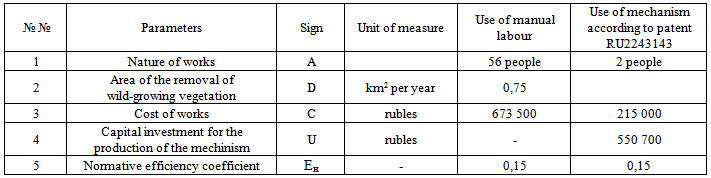
For economic evaluation of the proposed technical solution, implemented, for example, according to patent RU2243143C1, we used the method of financial and investment analysis and the audit when introducing new technology [17]. As a basic sample we take the lifting electromagnet of model M42B. According to the data of Yelets Branch of Yugo-Vostochnaya Railway (Southeastern Railway) for 2005 the cost of the work to remove the wild-growing vegetation averaged 3% of the total cost of various kinds of repairs of tracks which in in money terms is equivalent to about 673500 rubles per year. On the basis on the above-mentioned, as well as using the data from the table, we will determine the annual economic effect from the introduction of the patent RU2243143C1 which allows to completely eliminatemanual labor in the removal of wild-growing vegetation from elements of railroad tracks attributed to Yelets Branch of Yugo-Vostochnaya Railway (Southeastern Railway).For this purpose we use the following indicators.1. The coefficient of comparative economic efficiency, determined by the dependence: 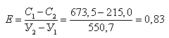 2. The coefficient of reduction of costs to the respective processed area for removing wild-growing vegetation by manual and mechanized ways can be determined by the dependence:
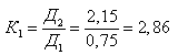 3. The given costs at the manual works -
 The given costs at mechanized works
  4. The given costs, taking into account the coefficient of reduction to equal processed area with wild-growing vegetation:
  On the basis of the above-mentioned we will calculate profits which the track department will get annually using the mechanized method for removing wild-growing vegetation in spring and summer time:
Table 1. Design parameters
 |
| |
|
4. Conclusions
Given the above, as well as proposed solutions, geometric and kinematic parameters which allow to assess the performance of the latter, the following conclusions and suggestions.1. The analysis of bibliographic sources dedicated to machines for mowing grass and wild-growing vegetation shows that all known designs of this kind can not be fully used by track department services of road offices of the Russian Federation while doing preventive and repair works connected with the maintenance of the railway track in proper state, ensuring safety of train operation and mechanization of labor-intensive processes in their manufacture.2. The analysis of domestic and foreign sources has allowed to develop at the level of inventions (RU2243145 and RU2242859) technical solutions which allow to mechanize the process of removing wild-growing vegetation from the profile elements of the railway track, to improve the quality of such works and their productivity, as well as to completely eliminate manual labor for such operations. At the same time we developed also at the level of inventions (RU2243142, RU2239977 and RU2243143) prospective technical solutions aimed at removing wild-growing vegetation from slopes and areas of the railway track. They have high production efficiency of such technological process.3. The calculations allowed to justify rational parameters of elastic pins, to assess the strength of their bedding-in in the discs, to develop rational design of centrifugal governor which is installed in hollow sections of the rod of the mower that are connected with the determination of the spring rigidity C = 4.5 kg/mm, the diameter of its coil dB = 6 mm, the outer diameter D = 45 mm and the length of the spring l = 137 mm, and also to determine kinematic parameters of the pneumatic rotary mower .4. The calculation of economic efficiency of the possible introduction of the technical solution, e.g. according to patent RU2243143, into practice showed that profits of the track department service of Yelets Branch of Yugo-Vostochnaya Railway (Southeastern Railway) can make 317.3 thousand rubles per year.5. Proposed products were given to the Management Department of Yugo-Vostochnaya Railway (Southeastern Railway) (branch of OJSC “Russian Railways”) to Yelets Branch of Yugo-Vostochnaya Railway (Southeastern Railway), and also to Technical Policy Department of OJSC “Russian Railways” as recommendations for further study, revision and possible implementation of the proposed constructions in practice. It is also recommended for various enterprises that produce similar machinery for repair-and-preventive track works on railway transport, both in our country and abroad.
References
| [1] | A.N. Karpenko, V.M. Halanskii, Selskokhoziaistvennye mashyni (Agricultural machinery) - 6th edition - M. Agropromizdat, 1989 – 527 p. |
| [2] | E.N. Konyushkov, Issledovanie uslovii raboty i obosnovanie kinematichekikh paramenrov rezhushchikh apparatov selektsionnykh zernouborochnykh machyn. Doc.of Technical Sciences Dissertation. Lithuanian agricultural academy, 1969 – 140p. |
| [3] | B.I. Turbin. Novyi mechanism privoda nozhei rezhushchikh apparatov kosilok. Works of the Turkmen agricultural institute, Volume XV, Ashkhabad, "Ylym", 1970 – 3p. |
| [4] | D.A.Chudakov,Osnovyteoriisel’skokhoziaistvennykhnavesnykhagregatov (Fundamentals of the theory of agricultural mounted units). - M.: Mashizd , 1954 – 128p. |
| [5] | A.B. Lurie, A.A. Granbchevskii, Raschet i konstruirovanie sel’skokhoziaistvennykh mashyn (Calculation and design of agricultural machines). - L.: Mashynostroenie , 1977 – 527p. |
| [6] | Sel’skokhoziaistvennye mashyny i osnovy ekspluatatsii (Agricultural machinery and basics of operation) MTP / B.N.Chetyrkin etc. - Moscow: Kolos, 1981 – 431p. |
| [7] | VISKhOM, Fiziko-mekhanicheskie svoistva sel’skokhoziaistvennykh rastenii kak osnovanie dlia proektirovaniia sel’skokhoziaistvennykh mashyn (Physical and mechanical properties of agricultural plants as the basis for the design of agricultural machines). - M.: 1960. |
| [8] | D.M.Shpolianskii, Tekhnologicheskie osnovy parametrov rabochikh organov sel’skokhoziaistvennykh mashyn (Technological basics of parameters of working agricultural machinery). - Tashkent. "Mehnat", 1985 – 250p. |
| [9] | Y.G.Panovko, Osnovy prikladnoi teorii kolebanii i udara (Foundations of applied theory of oscillations and shock). 4th ed. rev. and add. – L:.Polytechnic, 1990 – 272p. |
| [10] | V.I.Feodos’ev, Soprotivleniematrialov (Strength of materials). - Moscow: Nauka, 1970 – 543p. |
| [11] | I.M. Babakov, Teoriia kolebanii (Theory of oscillations). - Moscow: Nauka, 1968 – 559p. |
| [12] | A.A. Yablonskii, Kurs teoriticheskoi mekhaniki (Course of theoretical mechanics). Ch. P. Dynamika . 4thed., ext. - Moscow: Vysshaia Shkola, 1971 – 488p. |
| [13] | N.T. Volkov etc., Spravochnik mechanizatora morskogo porta (Reference book of a seaportmechanic). - M.: Morskoi transport, 1959 – 449p. |
| [14] | Y.I. Chuprakov, Osnoygidro-i-pnevmoprovodov (Fundamentals of hydro- pneumatic drives). / Y.I.Chuprakov. M:.Mashinostroyenie , 1966. – 157p. |
| [15] | L.T. Giliarovskaia, D.A. Endovitskii, Finansovo-investitsionnyi analiz i audit kommercheskikh organizatsii (Financial and investment analysis and audit of commercial organizations). – Voronezh: Publishing House of Voronezh State University, 1997. – 336 p. |
| [16] | E.V. Slivinskii, A.A.Zaitsev, O mechanizatsii udaleniia rastitel’nosti. Put’ i putevoe khoziaistvo (About mechanization of removal of vegetation. Road and track facilities). Monthly popular science, production and technical journal.№7.M:.Transport 2005 30p. |
| [17] | S.D. Ponomarev, L.E. Andreeva, Raschet uprugikh elementov mashyn I priborov (Calculation of elastic elements of machines and devices). - M.: Mashynostroenie, 1980 – 326p. |
| [18] | E.V.Slivinskii, A.A. Zaitsev, Rasshirenie ekspluatatsionnykh vozmozhnostei kosilok s rotatsionno-diskovymi rezhushchimi apparatami. Traktory i sel’skokhoziaistvennye mashyny (The expansion of operational capabilities of mowers with rotary-disc cutting mechanisms. Tractors and agricultural machinery). Monthly theoretical and practical journal. Mashinostroenie, № 7, 2006 – 39p. |
| [19] | V.A. Lepetov, L.N. Yurtsev, Raschet I konstruirovanie rezinovykh izdelii (Calculation and design of rubber products): Uchebnoe posobie dlia vuzov: - 3rd ed., rev. and add. - L: Khimiia, 1987 – 408p. |
| [20] | Bezstykovoi put’/ V.G. Al’brecht, etc. Ed. Dr. of Technical Sciences V.G. Al’brecht and cand. of Technical Sciences E.M. Bromberg - Moscow: Transport, 1982 – 206p. |
 Abstract
 Reference
 Full-Text PDF
 Full-text HTML