Slivinskij E. V., Radin S. Y., Gritchina I. N., Pakhomova E. V.
Yelets State University
Correspondence to: Slivinskij E. V., Yelets State University.
| Email: |  |
Copyright © 2012 Scientific & Academic Publishing. All Rights Reserved.
Abstract
This article presents the material relating to the development of advanced designs of devices aimed at improving safety in the maintenance and repair of tip biaxial trailers transported as part of autotractor trains. The proposed technical solutions created as inventions allow replacing wheels in emergency road service conditions more safely and effectively avoiding heavy manual labor, which is now widely used in practice. Analytical studies and calculations of force loading of structural elements such equipment of trailer units allow substantiating the basic rational geometrical parameters of such structures. We recommend our elaborations both domestic and foreign research and industrial structures in the field of Automobile and Tractor Engineering for their further study and possible implementation in practice.
Keywords:
Trailer, Tractor, Frame, Longeron, Hydraulic elevator, Cross bar, The spare wheel, Supporting device, Spring, stiffness, Tension
Cite this paper: Slivinskij E. V., Radin S. Y., Gritchina I. N., Pakhomova E. V., Improvement of Working Conditions in Autotractor Tow Vehicles Maintenance, International Journal of Traffic and Transportation Engineering, Vol. 3 No. 2, 2014, pp. 31-41. doi: 10.5923/j.ijtte.20140302.01.
1. Introduction
Improving the reliability of agricultural machinery is one of the most important tasks for improving the efficiency of agricultural production in our country. The successful solution of the problems of increasing the safe operation and reliability of the machines in operation, saving metal and lightweight construction is possible only on the basis of the theory and application in practice of designing modern methods and tools based on durability, wear-resistance and stiffness. One of the most important processes in the agronomic complex is transport operations of various cargoes, where a variety of trucks and tractor trains, consisting of tractors with trailers and semi-trailers is widely used. Tractor trucks are used mainly for transporting tractors and semi-trailers. We use wheeled tractors class 0,9 t, such as four-wheel tractor Т-28Х4М-С1 and T-40AM. Wheel tractors 1,4 t category are tractors МТЗ-52, МТЗ-80, ЮМЗ-6М, etc. Constructions of tractor tipper trailers are also diverse, and mostly they are biaxial tractor tipper trailers 2ПТС-4-793-01, 2ПТС-4-887, 2-ПТС-4М and heavy tractor semi-trailers 3-ПТС-12 carrying capacity of 12,0 tons mounted with wheel tractors K-700, etc. [1-3]. The basis of tractor-trailers design is chassis that is used for the installation on it platforms and devices. Usually a supplied chassis includes: frame, carrier, trailer coupling, brakes, tilt mechanism and electrical equipment. Trailer frame is a welded structure; it consists of two extruded longerons interconnected with crossbars. In the middle part of the frame there is a lower support of hydraulic elevator welded with a supporting bracket. All models of autotractor tipper trailers 2ПТС-4 have hydraulic elevators which are usually made of telescopic steel pipes entering each other. In order to improve the safety of maintenance and repair of parts and components of trailers in tight spaces, they are supplied with safety stands of platforms. In practice trailers are usually attached spare wheels, the place of attachment is selected mainly on the body or on the frames.A significant drawback of such a facility is the complexity and labor-intensive work because dismantling and installation of spare wheels is carried out manually. The wheel has a net weight of about 60 kg or more, that’s why a lot of accidents are registered during such operations. Therefore, in practice, we seek ways of creation and using of different devices to mechanize the process of spare wheels setting and dismantling operating in both manual and automatic modes.So, we have been conducting the budget research "Dynamics, durability and reliability of the transport and agricultural machinery agricultural sector in relation to Black Earth region of Russia" at the Department of Applied Mechanics and Engineering Graphics of Yelets State University for several years. One of its sections is devoted to studies aimed at improving of staff working conditions employed in the operation of autotractor trains including the ПАТС.
2. Purpose of the Research
The problem aimed at improving of working conditions, reducing injuries and safety repairs in the operation of autotractor trailers is very important. So, the object of this study is:1. Development of advanced designs at inventions of devices for mounting and dismounting of trailer wheels in case of emergency.2. Development of calculation schemes of such devices allowing making rational calculations to determine their kinematic and geometric parameters.3. Evaluation of technical and economic efficiency of the proposed technical solutions for possible introduction in practice.
3. Research Methodology
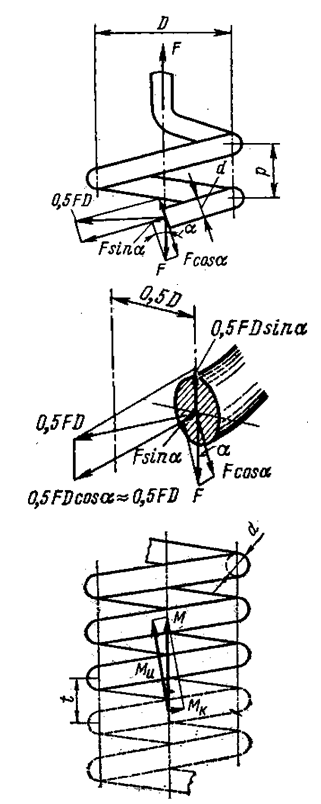
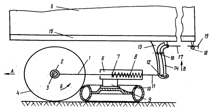
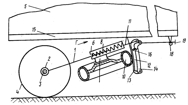
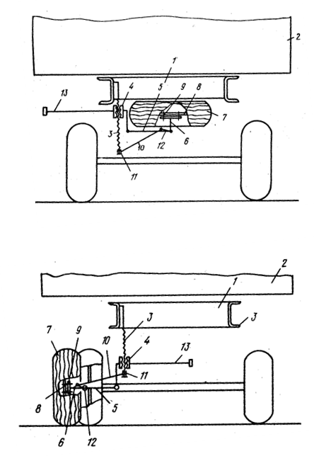
Analysis of numerous bibliographic sources, as well as domestic and foreign patents, allowed developing at the level of invention (SU1084159) a solution aimed at improving the safe operation of autotractor tipper trailers in conditions of installing or removing trailer spare wheels.So Figure 1 shows a general view of the tipper trailer on one side, Figure 2 shows a clamp ram (side view), in Figure 3 we can see a clamp ram (front view) and in Figure 4 there is a sectional support of the power cylinder mounted on the back of the trailer.Such tip trailer consists of a body 1, which by means of brackets 2 is situated at the other brackets 3, mounted on the longerons 4 of the trailer frame and fastened by means of locks 5. Longerons 4 are interconnected with crossbars 6, where the supports 7 with movable fingers 8 attached to the supporting bandage 9 are rigidly fixed. Supporting bandage 9 is rigidly connected to the body of cylinder 10 and is provided with a reel 11, which is wound around a steel cable 12 with a thrust 13 fixed by relatively longeron 4 with a retainer 14 provided with a handle 15 and a cable 16, attached by a spring 17 on the longeron 4. The body of cylinder 10 is provided with a ball pin 18. Mounted on the crossbars 6 hard brackets 19 are used for thrust of the spare wheel 20, suspended on the disc 21 with the tension springs 22 on the crossbars 6. In the body of the hydraulic cylinder 10 there is a telescopic rod 23 provided with a spherical finger 24 placed in the support 25 which consists of a fixed segment 26 and movable segment 27. The movable segment 27 is located on the finger 28 and is loaded with the torsion spring 29, the emphasis on fledging 30 fixed to the body 1. A control rod 31 is attached to the movable segment 27, and is suspended on the body 1 by means of bushings 32.Proposed solution works as follows. In order to make unloading of a body 1 it’s necessary to remove locks 5 (on the side opposite the discharge side) and serve the fluid pressure into the cylinder body 10. However, his telescopic rod 23 extends arrow A and tilts body 1. After unloading the cylinder body 1 is reversed, and the body 1 is lowered to trailer chassis.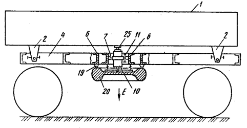 | Figure 1. General view of the tipper trailer |
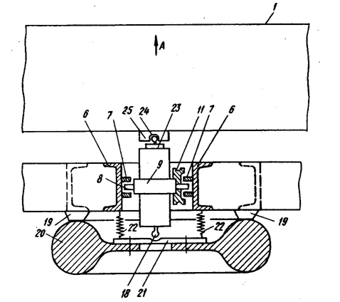 | Figure 2. Complete clamp ram side view |
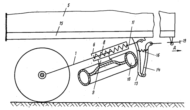
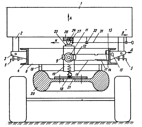 | Figure 3. Complete clamp ram front view |
In the case of replacement of failed wheel locks 5 are not removed and the control rod 31 is moved along arrow B, providing the rotation of the movable segment 27 of the support 25 on the finger 28 according to arrow C. After the rotation of the movable segment 27 at an angle of 90◦ a spherical finger 24 of the telescopic rod 23 can withdraw from the support 25, by means of manually moving handle 15 of thrust 13 and cable 12 along arrow D. Storing the cable 12 from the reel 11 ensures its winding, resulting in the stretchable cable 16 of the spring 17. Final position of thrust 13 with its rotation during arrow D is fixed with a retainer 14, and the body of cylinder 10 is rotated by an angle of 180◦, so its ball pin 24 fits the disk 21, and the ball pin 18 - to part 26. Thereafter, pressure is supplied to the body of cylinder 10 and the telescopic rod 23, resting against a ball pin 24 in the disc 21, moves the spare wheel 20 on arrow E downward, thus stretching the spring 22 . Then spare wheel 20 when it is on the ground is disconnected from the disc 21 and the failed wheel is mounted on the same disc, the cylinder is reversed and then by the force generated by them a spare wheel back in the position shown in Figure 2. After that thrust 13 is released and under the action of the spring 17 the cable 16 is unwound from the reel 11 on which a cable 12 is wound. The cylinder rotates by 180° again; this position is shown in Figure 2. Then control rod 31 is returned to its original position and is locked with the movable segment 27, ball pin 24 is in the support 25. Under the action of the springs 22, the replaced wheel 20 is urged firmly against the hard brackets 19 and thereby it is fixed to the rocking motion of the trailer.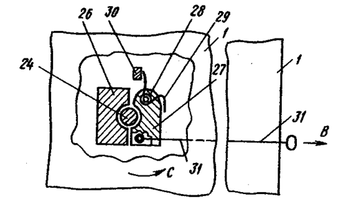 | Figure 4. Plug-in support of the power cylinder |
Analyzing the solution we can see the most responsible and important structural element is tension springs, so we give them the basic geometric characteristics that will allow to ensure its reliability in case of its use in practice .It is known [4] that the coil springs are characterized by stretching an average diameter D, they are usually loaded at the ends, and the load is reduced to acting forces P directed along the axis of symmetry of the spring and couples of moments M acting in the end planes perpendicular to the axis of z.Using a well-known method of sections, we assume (Fig. 5) that in the favorite section A spring is loaded with specified loads and any internal components of efforts such as N - normal, Q-shearing in two planes and M - bending and twisting moments will spring up.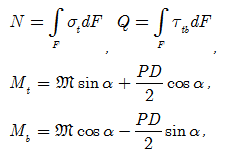
 | Figure 5. Design scheme of the elastic element |
Usually in practice force N and Q are of secondary importance compared with the twisting and bending moment Mtи Mbи that's why they take as design parameters in the study of the stress state of the spring installed in the auxiliary cylinder of brakes. It is known [4], that during the deformation of the spring under compression, its coils are moved progressively relative to each other, and this indicates the absence of relative rotation of the sections of the spring. And so, considering the movement of the spring is small compared with the corresponding dimensions, and its ends are fixed, we can use the following function allows to calculate the axial movement of the spring λ0 and moments  acting in the end planes perpendicular to the z-axis by the formulas:
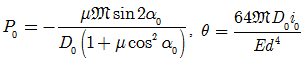 where, E - modulus of elasticity of the material;μ - Poisson's ratio;d - diameter of rod spring.To the ends of the spring loaded with moments M did not move in the axial direction, the axial force P0 and angular displacement θ of spring ends is determined by the formulas:
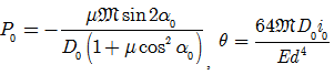 Earlier it was noted that during loading of the coil spring at the ends of the axial tensile forces and pairs of moments, its coils operate simultaneously torsion, bending and tension - compression, and in this approach the normal and tangential stresses in the cross sections of the coils can be determined according to known relationships:
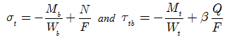 where, β - coefficient depending on the shape of the cross section of coils.But since the coils of tension cylindrical springs usually have a significant curvature, it has a significant impact on the law of distribution of internal forces in the cross-sections of coils, which leads to a significant increase in stress. Therefore, the calculation of stresses arising in the domestic fiber of coils in hazardous locations is recommended to determine the formulas obtained by the methods of N.A. Chernyshev’s [4] theory of elasticity, which have the form:
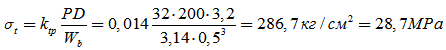
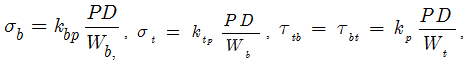 where, kbp, ktp, kp - coefficients depending on the elevation angle α and coil spring index C with Poisson's ratio μ = 0,3.The calculations showed that for lowering of spare wheel with disc 21 (see Figure 2) on the ground and then lifting emergency wheel to place its contiguity to the trailer frame tension springs 22 must develop a force of 0.2 tons (load factor is assumed to be 2,0). According to GOST 18794 - 80 this spring number 103 has the following characteristics: Dnar = 32 mm, wire diameter of 5 mm, number of turns n = 50 units. Material is steel 60S2 GOST 2590-51. Operating force of this spring is 1320 N. For such a spring, we calculate the numerical values of the normal and tangential stresses arising in the turns of a spring on the formulas:
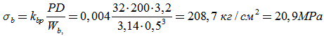

 | Figure 6. The apparatus for lifting the wheel when it is located on the ground |
 | Figure 7. A device in transport position |
 | Figure 8. The apparatus at the time of lowering the wheels on the ground |
where, kbp, ktp, kp when C = D / d = 138/22 ≈ 6 and α = 150 is selected from Table 4.5 [4], respectively are 0.002, 0.014 and 0.054.Analysis of the values of the normal stresses shows that their value for the steel 60S2 according to GOST 2590-51 is below permissible [σ] = 840 MPa and tangents [τ] = 380 MPa, so, the strength condition is satisfied.The calculations also showed that the introduction of the proposed design, aimed at improving of working conditions and safety is beneficial for both production and operating structures of the national economy , as machine-building enterprises of the output, for example, in an amount of 40.0 thousand units per year may a profit of 6180.0 thousand rubles a year. At the same operating conditions, work safety when servicing or repairing a trailer equipped with a safety device will be provided.Now let’s consider a device for removing and installing the spare wheel in relation to tractor trailers 2ПТС - 4, the design of which is also recognized as the invention SU988629.So in Figure 6 shows a device for lifting the wheel when it is located on the ground, in Figure 7 it is the same, but raised to the transport position and in Figure 8 it is, but when lowering the wheels on the ground.The apparatus consists of a telescopic arm made as a stationary rod 1, one end by a hinge 2 bound with shaft 3 of the trailer 5. The other end of the rod 1 is placed inside a rolling glass 6, which is a telescopic arm. Between the bottom of the glass 6 and thrust 7 of rod 1 there is a spring 8. Glass 6 is rigidly connected to the main bracket 9, where a spare wheel 10 is mounted, and traction 11 mounted for movement in a T - shaped groove 12 formed by plates 13 and 14 optional bracket, rigidly fixed to the frame 15 of the trailer 5. The plate 14 is hinged to the plate 13. Between the plates 13 and 14 a compression spring 16 is mounted. Plate 14 via the cable 17 and the guide block 18 is connected to the handle 19 of the drive.Mounting the wheels on the trailer is follows. Securing the spare wheel 10 on the main arm 9 under the force of the spring 8 of the telescopic rod arm 1, the spare wheel 10 is tight to the wheel 4. This is followed by the movement of the tractor with trailer 5 (tractor is not shown) by arrow A. This wheel 5 received angular rotation according to arrow B, due to frictional forces drags the spare wheel 10, as well as glass 6, which traction 11 slides along the T - shaped groove 12 in the up direction along arrow B until the traction 11 under the action of the spring 8 moves according to arrow G. As a result, the spare wheel 10 comes out of conjugation with the wheel 4 and takes a transport position (Figure 7). For removing the spare wheel 10 when replacing the spare wheel, the direction of the handle 19 along arrow D is moved whereby the plate 14, attached the torso 17 through the block 18 with handle 19 is rotated, overcoming the force of spring 16, thereby increasing the transverse dimension of the groove 12, and traction associated with the spare wheel 10, under the action of gravity is lowered to lock the latter in the hinge plates 13 and 14 of the bracket. Thereafter, the handle 19 is set to the initial position by moving it in the direction opposite the arrow D. The proposed technical solutions used in practice reduce the complexity of removing and installing of the spare wheel.Analyzing the structure of the proposed technical solutions it can be seen that the most responsible of its node is rod 1 with a movable glass 6, which in the first approximation can be represented as a beam, located on two supports loaded with concentrated force in statics and dynamics occurring at the point of installing the spare wheel. Calculation of the structural member at the flexural strength is not difficult and in this case the task is to determine the geometric characteristics of conventional beam arranged on two supports or define permissible load. As a calculation scheme (Fig. 9) annular section beam is adopted (thick-walled pipe GOST 8732-78) outer diameter d = 40 mm, inner diameter d1 = 28 mm and a length a = 1100 mm. The material is steel 20 GOST 8239 - 89 with [σ] = 600 kg/cm2 and = 60 MPa. We also assume that the load of its own weight of spare wheel with dynamic component arises when the trailer is P = 1800 N.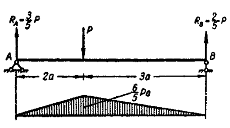 | Figure 9. Calculation scheme |
Determine the value of the permissible moment according to the formula [20]: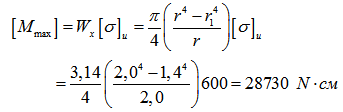 Now we calculate the maximum bending moment on the dependence:
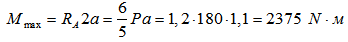 We now define the permissible load by the formula:
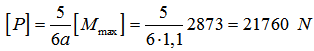 The result shows that the permissible load of 13 times higher than the operating one hence under operating conditions durability of construction element carrying the spare wheel is secured.Let’s consider another solution, also recognized the invention (SU1111927) and aimed at the exclusion of manual labor when replacing emergency spare wheels of trailers and can be used in the construction tip trailers 2ПТС-4.Figure 10 shows a perspective view of the trailer (side view), in Figure 11 we can see its cross - section in the zone of fastening the spare wheel on it, and Figure 12 is also a sectional view but with an arrangement of a spare wheel on the ground.Such a device comprises a screw 3 vertically mounted on the frame 1 of the trailer 2 with nut 4 which is rigidly fixed to a horizontally disposed step bracket 5 and holder 6 of spare wheel 7. The holder 6 is pivotally mounted on the step bracket 5 and is connected with disk 8 of spare wheel 7 with fastening elements 9. The screw 3 is connected to the holder 6 and rod 10, with one end 11 of traction 10 pivotally connected with end of the screw 3, and the other end 12 of the rod connected to the holder 6. To bring the device into operation horizontally located control lever 13 is mounted on the nut 4. For dismantling the spare wheel 7 it is disconnected from the frame 1, which in the transport position is fixed relative to the trailer body with closures elements (such elements are not shown), and turning the control lever 13 around the screw 3 is driven by the nut 4, the latter moves down the screw 3. As step bracket 5 is rigidly connected with the holder 6 and spare wheel 7 with nut 4, they are also moved down. While driving down the spare wheel 7 rod 10 connecting the screw 3 and the holder 6 aims to deploy hinged on a step bracket 5 holder 6 with the spare wheel 7 in the plane of the step bracket 5. In the end of stroke nut 4 spare wheel 7goes from horizontal to vertical position and contacts with the road. After that, disconnect the attachment elements 9 and roll away spare wheel 7, replacing the failed main wheel of trailer in the usual way. Mounting the spare wheel is carried out in reverse order. As a result, it is clear that the use of the proposed technical solutions permits to reduce the complexity of mounting and dismounting the spare wheel and improve working conditions for maintenance of the device by performing mounting operations outside the trailer, interpreting the spare wheel from a horizontal to a vertical position, that is convenient to roll the wheel for replacement.Analysis of the proposed structure shows that the most responsible of its structural component is a kinematic pair screw-nut and therefore we perform the calculation of its geometrical parameters of the automotive tractor trailer 2PTS-4 with own weight of wheel together with the details (Fig. 8) is 75 kgf from the standpoint of evaluation of its strength characteristics. We use the design scheme shown in Figure 12. As practice shows, unsatisfactory work of helical gears is often caused of thread wear.
 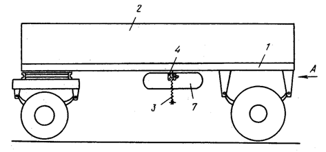 | Figure 10. General view of the trailer |
 | Figure 11. Mounting wheels on the trailer and setting it on the ground |
Therefore, the basic calculation of helical gears is the calculation of depreciation, which determines the diameter of the screw and nut height. Checking the average pressure p in the thread, we assume that all the threads evenly loaded with screw material is hardened steel 45 and for nut is bronze.We define the pitch diameter d2 according to [7]: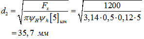 Fa - external axial load, 1200 N;ψН - factor for buttress thread, 0.5;ψh - the coefficient of height gages, 0.2;
 - allowable pressure (natural steel - iron), 5 MPa.According to GOST 9484-81 install d2 = 40 mm on spindles.We calculate the pressure in the thread for a couple of screw-nut by the formula [7]:
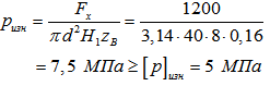 where, Fa - external axial load , 12000 N ;d2 - pitch diameter, 40 mm;H1 - working height thread, 8 mm;zB = H1 / p = 0,16 ( p is the thread pitch is 50 mm);
 - allowable pressure of 5 MPa.
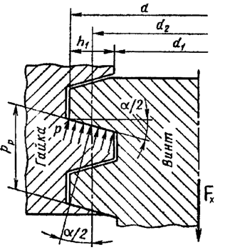 | Figure 12. Design scheme |
It is seen that received pressure pизн was higher permitted [p] изн but according to the recommendations given in the paper [7] where it is said that when a rare work, as well as for nuts of small height the value can be increased by 20%, that is [p] изн = 6 MPa, and if finally for making kinematic pair screw-nut use natural steel - antifriction iron ACHV - 2, then the strength of the depreciation will be fulfilled. Now define the height of the nut from the formula H = pz = 3 ∙ 50 = 150 mm.It is known that not only two-axle tipper trailers and semi-trailers of mounted mainly by tractors have been widely used in practice and problem of spare wheels mechanized installation on them is also important. Therefore, we consider the technical solution also recognized the invention (SU1659283), which can be used in the practice of using heavy trains including tractors and trailers.Fig.13 shows the end view of the trailer from the support device, and its sectional view taken along A-A.Semi-trailer consists of a frame 1, on which there are the body 2 and the support legs 3 of the drive mechanism 4 and its control lever 5. In support legs 3 support rollers 6 and movable levers 7 are fixed. They are provided with spring-loaded compression springs and the bell cranks 9, which interact with the ratchet wheels 10 also rigidly secured to the support legs 3. Levers 7 are pivotally connected with arcuate shoes 11 which are in contact with the spare wheel 12.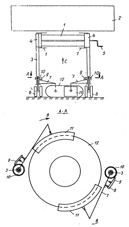 | Figure 13. An end view of the semi-trailer and its sectional view taken along A – A |
Operation is as follows. To install the spare wheel 12 to semi-trailer the latter is laid on the ground as shown in Figure 1, and turn the levers 7 along arrows B so that the shoes 11 came into contact with the spare wheel 12 and covering it both sides (Fig. 13) . Rotating the levers 7 along arrows B occurs by sliding double-arm levers 9 of the ratchet wheel 10, wherein as soon as their shoes 11 will cover the wheel 12, backtrack from the latter is expelled due to the double-arm levers 9 of the ratchet wheel 10. After shoes 11 tight cover spare wheel 12, manually rotate the handle 5, allowing through the gears 4 to climb support posts 3 along arrow C. Once the spare wheel 10 in conjunction with the support legs 3 and the supporting wheels 12 reach a predetermined height, a trailer receives movement. To replace the spare wheel of semi-trailer support legs 3 in conjunction with the wheel 12 are lowered to the ground in the direction opposite to arrow C and release the ratchet wheels 9, which makes it easy to turn the levers 7 and to release spare tire 12 from under shoes 11. Described processes may be repeated several times.To calculate the element base of ratchet mechanisms (Figure 14) installed, for example, on the racks of semi-trailer MAЗ5205A as inputs accept the following calculation scheme and indicators: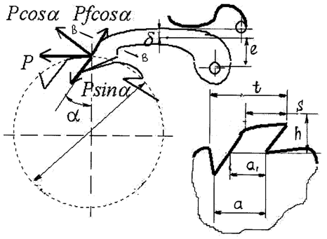 | Figure 14. Calculation scheme |
Own weight of wheel model 12,00 - 20, G = 123 kg, the torque on the shaft of the ratchet wheel Mкр = 200 N∙ m allowable line pressure per unit length of the tooth q = 400 N /mm, the number of teeth of the ratchet wheel at z = 15, rotation of the ratchet wheel α = 3600 / z = 120 and ψ = 2,0, coefficient characterizes the ratio of the width of the ratchet wheel to the module, and is selected from the table depending on the material of the wheel (in this case, steel 45) . Using this data, define a module m of the ratchet wheel by the formula [7]: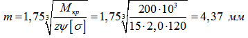 Definitively establish on GOST 2.770 - 68 modulus equals m = 6 mm.Inspect the line pressure by the formula [7]:
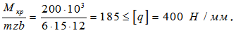 where, b - width of the tooth, which is defined as b = mψ = 6 ∙ 2 = 12 mm.It is seen that the calculated value of the line pressure q is lower than admissible value in 2.16 times; hence the load acting on the tooth of the ratchet wheel from its pawl does not cause failure of the kinematic pair.Define stress arising in the dangerous section B - B for this pawl previously calculate the following parameters such as circumferential force P, the moment of resistance of pawl W in this section, and the force F causing tension of pawl according to the formulas:
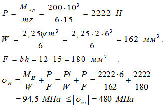 It is evident that the strength condition is satisfied.Now we define the axis diameter of pawl according to dependencies:
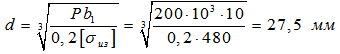 Finally, we take pin diameter of pawl equal to 28 mm.The following technical solution is also recognized as the invention (SU1047762) and aimed at eliminating of manual labor when replacing emergency spare wheels of trailers, and can be used not only in the construction of tip trailers 2ПТС - 4 model, but in other models widely used in the world. It should be immediately noted that this design is very simple compared with the previous ones, and it’s important that it is not fixed on the body of the trailer but on its frame, which allows you to use tip trailers not only trilateral, but quadrilateral unloading.Figure 15 shows a side view of the trailer to the proposed technical solution, in Figure 16 we can see a top view of the frame of the trailer and the time of dismantling the spare wheel when transferring it from a horizontal to a vertical position.
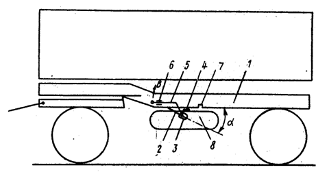 | Figure 15. General side-view of the trailer |
The device of a spare wheel mounting comprises the axis 2 rigidly connected with the frame 1 at an angle α to the horizontal plane and an angle β to the longitudinal axis of symmetry of the trailer. Angles α and β preferably are 45◦. In the axes 2 a bush 3 is rotatable mounted, where a lever 4 and a lever 5 are rigidly secured, forming a double-armed lever. On frame 1 clamps 6 and 7 of wheel 8 position are mounted cooperating with the handle 5. Wheel 8 is pivotally mounted through plate 9 and the hinge arm 10 on the end of lever 4. Lever 4 is connected with the frame 1 of trailer with spring 11.The device operates as follows. In the operating state of the trailer when driving or sludge a spare wheel 8 fixed to the end of the arm 4 is kept under the body of the trailer in the pressed position to the frame 1 through gripping the handle 5 with a clamp 6. For dismantling the spare wheel 8 dismiss clamp 6 of handle 5 and carrying the latter along arrow A, turn the lever 4 with spare wheel 8 round axis 3 until wheel 8 touches the ground. The spring 11 is elastically deformed, ensuring smooth movement of the wheel and the handle 5 misses the capture of clamp 7.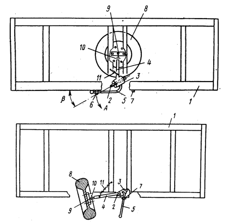 | Figure 16. Wheel position on the frame and on the ground (plan view) |
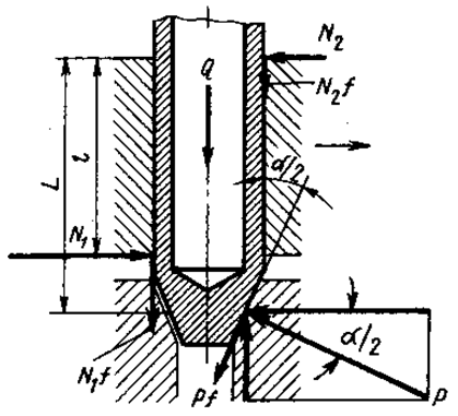
Disconnecting the spare wheel 8 from plate 9, roll out and use it for other purposes. Mounting of the spare wheel is carried out in reverse order. In this case the spring 11 being compressed helps to lift the spare wheel 8. When installing the proposed technical solution to the frame 1 of the trailer errors when installing axis 2 can be set by swivel spare wheel 8 with lever 4 .Analyzing the structure of the proposed device shows that it is very simple in design compared to the previous ones, but in practice there can be problems with effective work of clamps 6 and 7 and, therefore, the latters should have a high reliability of the locking. So, as fixers we choose the structure shown in Fig.17, and the calculation of the geometrical parameters we fulfill according to known methods [6].On the calculation scheme of clamp is seen (Fig. 17) that when moving the handle 5 in the capture of clamp 7 on its conical surface there is force tending to raise the clamp determined according to: where, Q - load of the spring retainer, N;α / 2 - half of the central angle of the cone, deg.Such a force P causes reactions N1 and N2 in the extreme points of clap railing, which can be determined by the formulas:
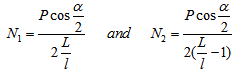
 | Figure 17. Calculation scheme |
The friction forces N1f and N2f also hinder the rise of clamp (f - coefficient of friction) and the friction force component Pf occurs at the application of the force P and equals Pf cosα/ 2. Then from the equilibrium condition can write the following equation: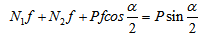 Substituting into this equation the values of N1 and N2 as a result we obtain the following relationship:
 This expression defines a threshold angle α at which the option to climb the clamp and on the basis of the recommended ratio L / l equals to 1,25 and the size of the handle section 5 (tube outer diameter of 50 mm and length 700 mm) found that the angle α should be equal 25°.
4. Results of the Study
Based on the foregoing, the following conclusions and suggestions can be made:1. Analysis of both domestic and foreign designs of automotive trains shows that the latter have a significant disadvantage that in case of replacement of emergency spare wheel is often necessary to use manual labor, as well as the trailer wheels, depending on the model, have their own weight of 60 kg and more, then in practice this operation frequently results in accidents. So today, there is a problem aimed at mechanization of production of these works.2. Given the foregoing as inventions (SU1084159, SU988629, SU1111927, SU1659283 and SU1047762) we developed technical solutions of devices that will improve the work conditions when replacing emergency spare wheel and thereby reduce occupational injuries in the industry.To establish a rational geometric and kinematic parameters of such devices there are developed physical models and known techniques used to determine them. For example, in the first case we selected according to GOST 18794 - 80 number 103 a spring having characteristics such as Dнaр = 32 mm, the wire diameter of 5 mm, number of coils n = 50 units. Material is steel 60С2 according to GOST 2590-5 and operation force P = 1320 N. In the second case, the support element adopted annular section beam (thick-walled pipe according to GOST 8732-78) outer diameter d = 40 mm, inner diameter d1 = 28 mm and a length a = 1100 mm. Material is steel 20 GOST 8239 - 89 with [σ] = 60 MPa. The third structure is configured strength calculation of the kinematic screw -nut pair, the material of the screw is natural steel and antifriction iron ACHV 2 for nuts, wherein the screw diameter is 40 mm and the nut by the formula H = 150 mm. The fourth structure the ratchet wheel module of equal to m = 6 mm is defined and installed in accordance with GOST 2.770 - 68, and the calculated value of linear pressure q attributable to the tooth of the ratchet wheel, which was below the allowable value in 2,16 times. And for the latest technical solution threshold angle α = 250 is defined, where the chance of lifting the clamp of handle device management, based on the recommended ratio shoulders L / l, equal to 1,25. 3. Results of the study are recommended for domestic and foreign transport companies, automobile industry, science and engineering departments working in the automotive industry for the study and analysis of the proposed designs for possible further put them into practice.
References
| [1] | Short automotive handbook. 10th ed. rev. and add. - Moscow: Transport, 1989. – 220 p. |
| [2] | Vysotsky M.S. etc. Car and tractor trailers. M. Mashgiz, 1992. – 161 p. |
| [3] | Zakin Ya.Kh. Road trains, vehicle design development. Proceedings of NAMI, no. 12. Mashgiz, 1995. |
| [4] | Ponomarev S.D., Andreeva L.E. Calculation of the elastic elements of machines and devices. - M.: Mechanical Engineering, 1986. – 326 p. |
| [5] | Tchudakov E.A. Theory of car. M.: Mashgiz, 1990. – 272 p. |
| [6] | Theory and design of the car. Tutorial for motor colleges / V.A. Illarionov, etc. - M.: Engineering, 1995. – 368 p. |
| [7] | Orlov P.I. Design Basics: Reference Manual. In 2 books, Bk. 1/ Ed. P.N. Uchaeva - Ed. 3rd, rev. - M.: Mechanical Engineering, 1998. – 560 p. |
| [8] | Shchukin M.M. Hitches cars and tractors. M -L.: Mashgiz, 1991. – 207 p. |
| [9] | Smirnov G.A. Theory of the motion of wheeled vehicles. Textbook for students of special mechanical engineering universities – the 2nd ed., ext. and rev. - M.: Mechanical Engineering, 1990. – 352 p. |
| [10] | Slivinskiy E.V. Improving of performance trailed vehicles on the basis of effective scientific and technical solutions. Dissertation for the degree of Doctor of Technical Sciences. Oryol, 2010. - 334 p. |
| [11] | Slivinskiy E.V., Radin S.Y., Gridchina I.N. Improving the performance of automotive trailers (monograph) LAP LAMBERT Academic Publishing is a trademark ISBN 978 -3- 659- 46392 -1Saarbrucken, Germany, 2013. 156 p. |
| [12] | Job of automotive tires. Ed. V.I. Knorozov. Moscow: Transport, 2001. – 238 p. |
| [13] | Chuprakov Y.I. Fundamentals of hydro - pneumatic actuators / Y.I. Chuprakov. Mashinostroyeniye, 1996. – 157 p. |
| [14] | Nemtsov Y.M., Majboroda O.V. Performance of cars regulated wiyh requirements of safety. - Moscow: Transport, 1997. - 141 p. |
| [15] | Babkov V.F. Road conditions and traffic safety. - Moscow: Transport, 1992. - 288 p. |
| [16] | U.S. patent number 4301954. |
| [17] | UK patent number 2068862. |
| [18] | Trailers and semi-trailers MAZ. M.: Transport. 2008. – 153 p. |
| [19] | Markelov S.P., Krylov Y. N. Modern designs of trailers in capitalist countries. M.: TsNIIavtoprom, 1996. – 118 p. |
| [20] | Feodosiev V.I. The resistance of materials. Moscow: Nauka, 2007. - 544 p. |
| [21] | Gong, Xu, Zhengqi Gu, Jian Ye, Xu Yan, and Zhiming Zhao. "Surrogate Model for Aerodynamic and Handling Stability Optimization of a Tractor-Trailer in Crosswinds." In Proceedings of the FISITA 2012 World Automotive Congress, pp. 189-200. Springer Berlin Heidelberg, 2013. |
 Abstract
 Reference
 Full-Text PDF
 Full-text HTML