E. Slivinsky1, S. Radin2, T. Mitina3, D. Klimov4
1Dr. of Engineering Sc., Prof., Yelets State University name I.A. Bunin (Russia, Yelets)
2Cand. Sc. (Engineering), associate Prof., Yelets State University name I.A. Bunin (Russia, Yelets)
3Assistant Prof., Yelets State University name I.A. Bunin (Russia, Yelets)
4Teaching assistant, Yelets State University name I.A. Bunin (Russia, Yelets)
Correspondence to: E. Slivinsky, Dr. of Engineering Sc., Prof., Yelets State University name I.A. Bunin (Russia, Yelets).
| Email: |  |
Copyright © 2012 Scientific & Academic Publishing. All Rights Reserved.
Abstract
This article presents information related to the development of promising structures which are part of the automatic performance within the structure of the brake indirect freight and passenger cars. This automatic performance is simple in construction and one of the options allows positive infinitely variable over a wide range of cargo located in the back of the car to change by pressing the brake pads on the axis of the wheelset. Grounded goals and objectives of the study and based on an analysis of numerous domestic and foreign literature and patent sources on this problem developed at the level of 6 inventions RF effective and simpler in design to the automatic performance. Method of calculation and are designed as a first approximation the basic geometric and kinematic parameters of the above structures. Results of the study recommended research and industrial structures in the area of car building for the purpose of further study and possible implementation in their practice.
Keywords:
Bow, Bogie, Mounted wheels, Air brake cylinder, Rodding, Automatic performance, Air brake system, Brake control valve
Cite this paper: E. Slivinsky, S. Radin, T. Mitina, D. Klimov, Development Automatic Performance for Freight Stock, International Journal of Traffic and Transportation Engineering, Vol. 3 No. 1, 2014, pp. 20-29. doi: 10.5923/j.ijtte.20140301.03.
1. Introduction
It is known[1-8], which is one of the most important criteria for assessing the operational work of the rolling stock is safety. Therefore, all the administrative and technical measures on the railways focused on content in the permanent health of all railway structures, platform, rolling stock, equipment and machinery, signaling arrangement, and communication through their inspections, preventive maintenance and, of course, their continuous improvement through the introduction of advances in science and technology. Modern freight fleet car includes a variety of types and designs of this type of rolling stock, because of the need to meet the various requirements imposed on them. All types and kinds of the rolling stock must have a high carrying capacity, to provide a comfortable environment for transportation of goods, have the versatility to have a high utilization rate, etc. These factors determine the number of requirements to the structure of freight stock, which mainly consist in equipping them with automatic braking drag shoe, the use of automatic couplers, to improve and standardize the running parts, etc.Currently, the designs of freight stock are widely used power brake apparatus include automatic performance, which are intended to regulate the press force the insert according to the self-weight load located in the bodies of the latter.Analysis of the existing auto mode, both domestic and foreign rolling stock[1-9, 16] shows that to date, no such technical means that would allow to adjust the press force the insert do not just step, as is the case in serial constructions automatic performance, but seamlessly with a wide range of braking operation, depending on the amount of cargo in the superstructures of cars and platforms.
2. The Purpose of the Study
For a number of years at Yelets State University name I.A. Bunin at the Department of Applied Mechanics and Engineering Drawing for the period 2009-2013 gg commissioned Eletski center of Belgorod region South Eastern Railway, as well as the Office of the South-Eastern Railway branch of Open Society Akionernoe "Russian Railways" conducted research aimed at improving the efficiency and safety of rolling stock and its modernization. One of the sections of this research topic is related to the development of technical means to create a more perfect and simple in design to the automatic performance, which can be used not only on the load, but the passenger rolling stock. Therefore, the aim of the study was to conduct a patent search, preparation of application materials to the alleged invention, development and synthesis, as well as the identification of a number of structural, geometric and kinematic parameters of the automatic performance is intended for freight and passenger cars. Taking this into account and analyzing the numerous references, as well as domestic and foreign patents[20-26], has developed a number of promising automatic performance recognized as inventions: RU2402443, RU2399526, RU239525, RU2412074, RU2412844, RU2412843.
3. Method of Research
It is known[7,10-12] that the automatic performance designed to automatically control the pressure in the air brake cylinder (ABC), depending on the load of cars and therefore have the latest eliminates the need to manually switch between inhibition of the diffusers.For example, automatic performance is condition № 265-002 (Fig. 1) mounted on freight stock between air distributor and the air brake cylinder and consists of a housing 13 of the damper, the pneumatic relay 2, the motor nose 26 and 1. By motor nose connected plumbing from the brake control valve (BCV) and to the air brake cylinder (ABC).In the damper of the damper bucket 20 is a guide bar 17 loaded by a spring 21. The disc damper bucket ture valve 24 is press-fitted to the orifice hole diameter of 0.5 mm. Drive bucket is sealed with a rubber sleeve and has a felt element drip ring. The case of the damper (the cavity above the bucket) sealed rubber spacer 23 and the lid 22 is closed. The cavity under the damper bucket filler block 18 is sealed with a cumulative 19. Damper bucket rod with a screw 14 rigidly connected to the die block 15 and the shank 16 biscuit guide 12 which is placed in a glass 11 inserted into the plug 9 and the metal ring 10 held. The die block 15 includes a slit coils 9, on which the shank screw the regulating nut 5 with 4 focus, fixed cotter pin and jam nut 6. Inside the plug are two springs 7 and 8. In the case upper cavity 26 of pneumatic relay 27 arranged in the hollow bucket rod and double-seated valve 29 with a spring. In the case 2 of the lower cavity is the pneumatic relay bucket 32. Upper bucket 27 is spring-loaded by the stem 28 and the lower bucket 32 is spring-loaded from the disk 31. Shafts 27 and pistons 32 are supported on the cantilever 25 and the pivot cantilever is a split key 16. This automatic performance is mounted on the frame of the car and its work is as follows. When you load the car due to the deflection of springs automatic performance emphasis rests on a base plate fixed to the cross bar connected to the side walls of the wagon carts. Consequently, the yoke 9 is recessed in the damper housing part and the damper bucket together with the die block moves upwards and the split key and the ratio of shoulder "A" and "B" of cantilever 25 (Fig.1) varies depending on the load carriage.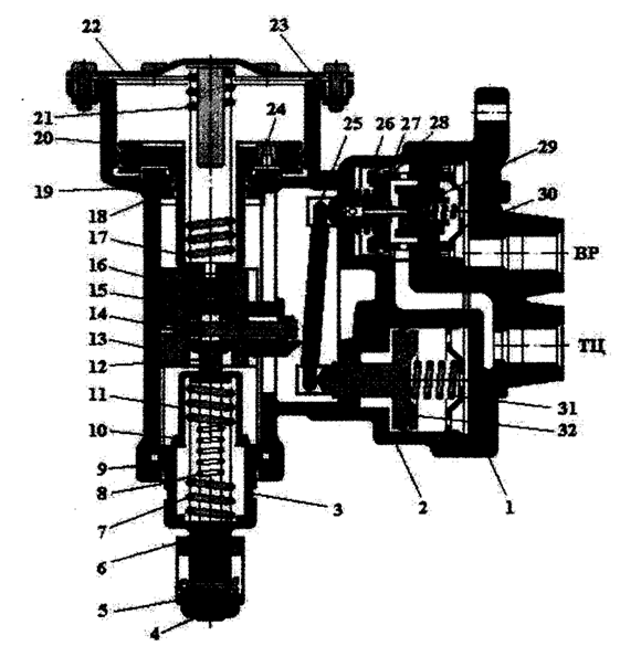 | Figure 1. Automatic performance is condition № 265-002 |
Thus, the unladen car damper bucket is at its lowest position, and loading the car for more than 75% - 80% of the maximum - the highest position. Full stroke damper bucket is at the same 38-40 mm.At the equipment carriage cast-iron insert and the presence of automatic performance, the brake control valve is set to laden braking mode, and the mode selector lever brake is withdrawn.If the car is equipped with composite blocks automatic performance, its brake control valve is mounted on the average braking power. There are also automatic performance conditions № 265-002 and № 605 respectively shown in Figure 2 and Figure 3 and used on the motor-wagon rolling stock. | Figure 2. Automatic performance is condition № 265-002 |
 | Figure 3. Automatic performance is condition № 605 |
Analysis outlined above shows that all the known structures are complex in automatic performance apparatus and therefore are not sufficiently reliable in practice. Given our past, as inventions, a number of technical solutions that simplify the design automatic performance known members of the air brakes. For example, the first solution has shown in Figure 4 as a circuit diagram freight stock brakes (RU2402443).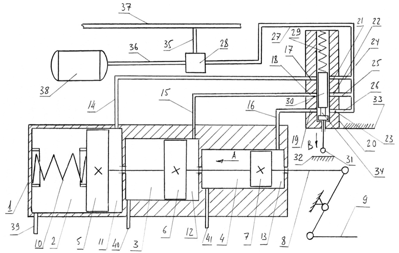 | Figure 4. Automatic performance is condition (patent RU2402443) |
In this case, the drag shoe consists of a wagon body air brake cylinder 1 is provided with internal cavities 2, 3 and 4, in which bucket are respectively 5, 6 and 7. Buckets 5, 6 and 7 are rigidly fixed on the guide bar 8 is pivotally connected to the linkage control of the insert 9. Between the bucket 5 and the air brake cylinder casing 1 is a compression spring 10. Subpiston space 11, 12 and 13, air brake cylinder 1 via the pipes 14, 15 and 16 are connected to channels 17, 18 and 19 of the body 20, the auto mode, which performs other channels 21, 22 and 23 connected by conduits 24, 25 and 26 with conduit 27 diffusers 28. Inside housing 20 is located automode resilient compression spring 29, the plunger 30 provided with a fifth 31 in contact with the sidewall plate trolley 32. The case itself automatic performance 20 is rigidly fixed to the frame 33 freight stock. On the hydraulic piston 30 is neck 34. The brake control valve 28 is connected pipes 35 and 36, respectively, with the brake pipe 37 and a spare bulb 38. The internal cavities 2, 3 and 4 of the body air brake cylinder 1 are communicated respectively with the atmosphere through stub duals 39, 40 and 41.Freight stock brake works as follows. Assume that the wagon is unloaded condition comprising a freight train, and if necessary its inhibition are widely known manner lowered air pressure in the brake line 37 which leads to its receipt of the spare bulb 38 through brake control valve 28 in conduit 27, then an additional channel 23 and the neck 34 in the hydraulic piston 30 of the channel 19. From channel 19 compressed air flows further through conduit 16 to the subpiston chamber 13 of the housing air brake cylinder 1, thereby producing pressure on the bucket 7, which moves along the arrow A, driving the linkage control of the insert 9 Lipolysis thereby wagon (Figure braking pads and wheel pairs of the car is not shown). Such movement of the bucket 7 is possible due to the availability of stub dual 41 through which air is forced them into the atmosphere, as well as the provisions of the foot step 31 which is a gap relative to the plate sidewall truck 32 car. At the same time, the bucket 7 of the arrow A and facilitates displacement in the same direction, and buckets 5 and 6 as they are rigidly fixed on the guide bar 8. Consequently, such a move together to compress the compression spring 10. Once the need for braking has disappeared, commonly known in the art increase the air pressure in the brake line 37 which leads brake control valve 28, conduit connection 27 with the atmosphere. And then compressed under the action of compression spring 10 with the buckets guide bar 8, 7, 6 and 5 are returned to the original position such as shown in Figure 4, thereby disinhibition wagon. Such processes braking empty car and leave the brakes can be repeated many times. Now suppose that the freight wagon was partially loaded on its maximum payload and then by drawdown frame 33 of wagon for rotation in its shoks (Figures freight car bogie design not shown) abuts the foot plate 31 side wall trucks 32, which causes movement of the hydraulic piston 30 in the direction opposite to the direction and example, he takes a position where it will be located neck 34 so that the link between a channel 22 and 18 of the 20 automatic performance. In this case, depending on the size of the necks 34 and the length of the hydraulic piston end portion 30, located beneath it, it may happen that the rockers 23 and 19 are overlapped or not. Consider the case when they are closed, and the channels 28 and 18 are interconnected by the necks 34. Then, as described above and decreasing braking pressure line 37 to the same value as in the first case, and then the compressed air goes into subpiston chamber 12 through conduit 15, channels 18 and 22, conduit 27, brake control valve 28 from the storage bulb 38 . As a consequence of the compressed air in the cavity 12 will subpiston translational motion of the piston 6, also in the direction of the arrow A, carries with it the buckets 7 and 5, compressing the compression spring 10 and driving the linkage controls the insert 9. But as the diameter of the bucket 6 is greater than the diameter of the bucket 7, the force generated by them at the same pressure will be higher and, therefore, the braking force on the wheels of wheel sets also increase. If the rocker 23 and 19 does not overlap the bottom of the hydraulic piston 30, the pressurized air enters it in the sub piston space 13, and then the braking force to wheel sets grow not only from the action of the arrow A bucket 6, but also from the action in the same direction of the bucket 7. This total force is far higher than in the previous case, when the channels 23 and closed bottom 19 of the hydraulic piston 30.Now consider the option when the wagon is fully loaded weight with a high proportion corresponding to the maximum of its payload. In this case, the hydraulic piston 30 can occupy two positions, where the channels 23 and 19 they are not covered and covered only channels 22 and 18, or they are all open. In both cases, the same channels 17 and 21 are interconnected by the presence of the necks 34 therebetween. Consequently, in any case, compressed air to enter through the channels 21 and 17 in the subpiston space 11, and then the bucket 5 will move as according to arrow A, compressing the compression spring 10 and the resulting movement of the guide bar 8 to the linkage control of the insert 9, thereby braking loaded wagon. It should also be noted that the braking force is large, because the diameter of the bucket 5 is greater than the diameters of the buckets 6 and 7. At the same time, the hydraulic piston 30 can move to the top position, fully squeeze your compression spring 29. Then, all channels 17, 18 and 19 go compressed air so as to free them from their access channels 21, 22 and 23. It is understood that in this position the hydraulic piston 30 is implemented by the inserts on a large amount braking force due to the fact that all three bucket 7, 6 and 5 will be under pressure and compressed air in the amount of the guide bar 8 will exert maximum force exerted by the device in question. After unloading wagon the hydraulic piston 30 under the action of the compression spring 29 returns to its original position shown in Fig.4 by the fact that the distance between the frame 33 of the freight wagon and the bogie plate 32 will increase the sidewall and heel 31 will be released from contact with the latter. Further described processes can be repeated many times.Analysis described construction proposed technical solution shows that the main body is a knot in the air brake cylinder 1 provided with internal cavities 2, 3 and 4, in which buckets are respectively 5, 6 and 7. Given such a feature designed air brake cylinder for freight cars based on the fact that the course of his the buckets must match the course of serial air brake cylinder situation. № 188B in such a way that the brake lever gear used by the latter, has not been constructive change. Moreover, the initial diameter of the inner cavity 4 is selected equal to D = 356,0 mm, such as is the case with air brake cylinder situation. № 188B. It is known[15] that the stroke of bucket air brake cylinder situation. № 188B is 240.0 mm, and therefore the proposed technical solutions, the length of the internal cavities 2, 3 and 4 air brake cylinder are also equal to 240.0 mm. Then, the total length three cavities with the two baffles located between the cavities 3 and 4 are made of sheet δ = 8,0 mm, will be about 736.0 mm. Also known[9-12,16], which braking wagons repositories comprising freight trains use three modes are directly related to the change of air pressure supplied to the brake cylinder, while load carriages may be different. This mode is loaded when the pressure in the air brake cylinder is 0,39-0,43 MPa, average mode with pressure 0,24-3,0 MPa and empty mode 0.14-0.18 MPa. Let us consider for the proposed design brakes these modes in detail. The first characteristic mode is empty space 4 (Fig. 4) which has an inner diameter D = 356,0 mm and its piston operates at a bucket 0.14-0.18 MPa compressed air, the hydraulic piston 30 is in automatic performance lowermost position shown in Figure 4. In this case, the rod air brake cylinder inner diameter D = 356,0 mm arise force is exactly the same as it is in standard designs wagon brakes: 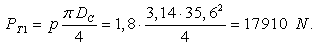 Now assume that the other wagon, belongs to the same floor of the train is loaded and the air pressure in its subpiston chamber 12 is fed air brake cylinder is the same as in the previous case, that is 0.18 MPa. But secondary mode, as noted above, the pressure must be equal 0,24-3,0 MPa, whereby in the case of serial air brake cylinder inner diameter D = 356,0 mm force exerted its rod should be:
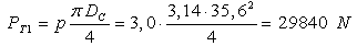 Therefore, the inner diameter of the cavity 3 to be configured so that, when applying it to the air pressure 0.18 MPa piston 6 would provide a force on the piston rod 8 29840 N. Therefore, its area should be equal to:
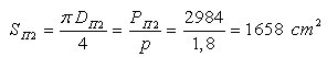 wherein the diameter is equal to,
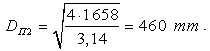 Now again suppose that another wagon, belongs to the same composition of the train is fully loaded and the air pressure in subpiston chamber 11 is fed air brake cylinder is the same as in the previous case, that is 0.18 MPa. But the loaded mode as noted above, the pressure must be equal to 0,39-0,43 MPa, whereby in the case of serial air brake cylinder inner diameter D = 356,0 mm force exerted its guide bar should be:
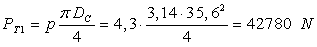 Therefore, the inner diameter of the cavity 2 must be made so that when applying it in the air pressure 0.18 MPa bucket 5 secured to the stem force 8 42780 N. Therefore, its area should be equal to:
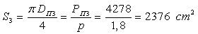 wherein the diameter is equal to,
 Analyzing the results obtained by calculations indicate that the air brake cylinder of the proposed technical solutions should have three sections of different diameter 365.0 mm, 460.0 mm and 550.0 mm, each length is 240.0 mm and the total length of the air brake cylinder is equal to 720, 0 mm. Despite such significant size, air brake cylinder to effectively ensure implementation of braking forces at fairly low values of air pressure is 0.18 MPa. This pressure is essentially a single stage and allows lower energy costs for the production of compressed air, and eventually to reduce its charging amount supplied to the brake pipe is more than twice. All this will also improve the operational reliability of the pneumatic brake no direct mode of action freight cars. It should also be noted that in order to reduce the dimensions calculated above and air brake cylinder may be of metal, for example, raise the pressure of compressed air to the empty mode from 0.18 MPa to 3.0 MPa and then the diameter of the portions may be reduced to about 1.4 fold, respectively, up 260.0 mm, 328.0 mm and 392.0 mm.The following construction of automatic performance is shown in Figure 5 as well as a circuit diagram rail vehicle brakes, as in Figure 6 general view of spool valve with a pressure relief valve and valve section (RU2399526).
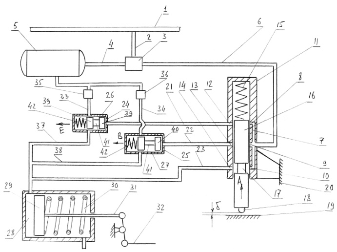 | Figure 5. Brake rail crew (patent RU2399526) |
 | Figure 6. Bypass valve pressure (patent RU2399526) |
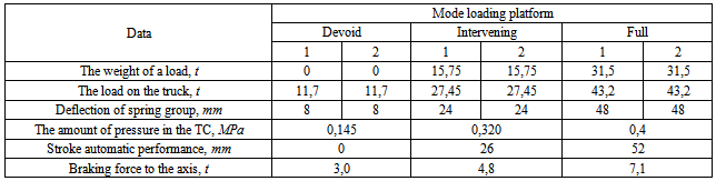
In this case, the rail vehicle brake consists of a brake line 1, line 2 associated with the brake control valve 3. The brake control valve 3 is also connected via line 4 with a reserve bulb 5 and the duct 6 with the longitudinal channel 7 connected to the transverse channels 8, 9 and 10 disposed in the housing 11 automatic performance. In the latter coaxially with the channels 8, 9 and 10 in the diametric plane of the housing 11 made automatic performance other transversely spaced channels 12, 13 and 14. Inside the housing 11 is movably automatic performance, the compression spring 15 spring-loaded hydraulic pistons 16 with neck 17 and foot step 18 contacting the sidewall plate trolley 19. The case itself automatic performance 11 is rigidly fixed to the frame 20 crew. Other transversely spaced channels 12, 13 and 14 through conduits 21, 22 and 23 are attached respectively to the end surfaces 24 and 25 of the spool valves 26 and 27, and conduit 23 to the cavity 28 above the piston air brake cylinder. Piston 29 is spring-loaded air brake cylinder by a compression spring 30 and its guide bar 31 is connected to the linkage control of the insert 32. Shell side of spool valves 26 and 27 via conduits 33 and 34 through the pressure relief valves 35 and 36 are connected to the reserve bulb 5 and the conduits 37 and 38 above the piston air brake cylinder cavity 28. Inside the spool valves 26 and 27 is movably arranged respectively spools 39 and 40 are provided with recesses 41 and the resilient compression springs 42. The spools 39 and 40 are provided with "L" shaped channel 43.Powered rail vehicle brake as follows. When the latter is empty (for example, freight car), parts, components are in the last position, as shown in Figure 5. Assume that the car is located in the train and service brake is applied thereto. This lowers the pressure in the brake pipe 1, for example, to a value such that the air pressure in the conduit 6, coming from the reserve bulb 5, be 0.2 MPa. In this case, the compressed air flows into the longitudinal bore 7 of the casing 11, automatic performance, and passing the recess 17, enters the transverse channel 13 and the conduit 23 enters the space 28 above the piston air brake cylinder. Under the action of the pressure bucket 28 moves to the right of Figure 5, and actuates the lever system 32 controls the insert. The passage of compressed air under such pressure through these parts is possible because the heel of the hydraulic piston 18 with a gap 16 is «δ» sidewall relative to the plate trolley 19. Once the train reaches a speed decelerates any desired value, the air pressure in the brake pipe is raised to 1 and then the value of the charging pipe 6 through the brake control valve 3 is connected to the atmosphere, thereby under the action of the compressed compression springs 30 move bucket 29 to its original position, and thereby dissolve the brake.Now consider the case when the wagon is not completely downloaded, and only about 50% of the maximum payload. Then, under the influence of sidewall plate 19 trucks due to subsidence spring suspension trolley comes into contact with the heel of the last 18 and the plunger 16 is moved by the arrow A at such a distance that it overlaps are channels 10 and 14, but it will create the conditions to pair with each channel 9 13 and its neck 17, but overlap channels 10 and 14 and will be blocked channels 8 and 12. Likewise, as described for the decrease of braking pressure in the brake pipe 1 and then the compressed air is also, for example, under a pressure of 0.2 MPa from the storage bulb 5 passes through the brake control valve pipe 3 in the longitudinal channel 6 and 7. But as the channels 10 and 14 as well as 8 and 12 closed, the compressed air through the transverse channels 9 and 13 flows into conduit 22 and the spool 40 moves along arrow B compressing its compression spring 42. Such movement of spool 40 will condition when its neck 41 is located between the conduit 34 and 38, providing a current of compressed air in cavity 28 above the piston air brake cylinder. It should be noted that the pressure relief valve 36 is adjusted, for example, pass compressed air from the storage reservoir to 0.3 MPa, and therefore the force on the piston air brake cylinder 29 will be higher than in the first case and braking half loaded crew increase. After the required speed reduction in brake pipe pressure is raised to 1 normative value, and the brake control valve 3 connects conduit 6 to the atmosphere and thus the pressure disappears and the pipeline 22 that provide movement of the spool 40 under the action of its compression spring 42 in compression direction reverse the arrow B. As a result, spool 40 will override lines 34 and 38, but connect the "T" shaped passage 43 with the conduit 38 and the conduit 22 (see Figure 6). Then the piston 29 together with the air brake cylinder guide bar 31 and the linkage control of the insert 32 under the action of compression spring 30 moves to the position shown in Figure 6, thereby dissolving the brake. Now consider the third case of inhibition of the crew, when it is fully loaded with a load corresponding to its maximum payload. Under such a load the hydraulic piston 16 elastically deforms more its compression spring 15 so that the neck 17 will be located between the channels 8 and 12, the channels 9 and 13 and also 10 and 14 they are closed. As in the previous cases in the braking mode the crew reduce brake pressure to a value of 1 is equal to 0.2 MPa, and then compressed air from the storage tank 5 and the air distributor 3 will pipe 6 and respectively 8 and fills the channels 12 and pipe 21. This will move the spool of the arrow E 39, which squeezing a compression spring 42, allows its neck 41 to interconnect conduits 33 and 37 and the compressed air goes from the reserve tank 5 via a pressure relief valve 35 which is adjusted, for example, pressure 0,4 MPa in the cavity 28 above the piston air brake cylinder, driving levers the insert 32. This process will provide on the plunger air brake cylinder 31 by the force greater than the values in the first two cases above. The braking performance of the crew in this case is provided. After the termination of required braking pressure in the brake pipe 1 is then raised to the normal brake control valve 3 and thus connects conduit 6 and through the ducts 8 and 12 and line 21 to the atmosphere, whereby the valve 39 should take under the influence of its compression spring 42 the position shown in Figure 5 and Figure 6, and then the "L" shaped channel 43 is connected to the cavity 28, air brake cylinder to the atmosphere. Vacation brakes performed. Subsequently, the processes described can be repeated several times.Consider the possibility of using the proposed structure, such as a Universal eight-wheel platform capacity 63,0 t model 13-401. Kerb weight (tare) platform is 23.4 m and a maximum speed of 120 km / h The platform is located on two two-axle carts 18-100 (CRI-X3-O), net weight of each of which is 4700 kg. Static deflection of the suspension bogies is 48 mm and it consists of five two-row helical compression springs with the flexibility of one set of 1,3-1,82 mm / mc. The platform is equipped with air brake system includes conventional brake control valve № 270-005-1, consisting of the main parts of a vacation rocker and the main part of the switch flat and mountain modes. The brake control valve provides the following braking parameters: charging pressure at the plain mode, 0,53-0,55 MPa, the mountain 0,63-0,65 MPa, the rate of braking waves with an external braking 230 m / s, with a full service 210 m / s . The filling of the air brake cylinder to 0.35 MPa with an external braking is 15-20c. The pressure in the air brake cylinder when laden mode is 0,39-0,43 MPa and unloaded at 0.14-0.18 MPa. Vacation time after a full service brake application at the plain mode, no more than 35 seconds. Air brake cylinder number 188B with an inner diameter of 356.0 mm and 240.0 mm bucket[15].Given these characteristics of the platform and its braking equipment, the geometrical characteristics of valves 35 and 36, and spool valve 26 and 27 (see Figure 6), as well as the gear ratio transmission control lever insert equal to 2.3 were calculated key figures of the proposed technical solutions, the results of which are summarized in Table 1. Analysis of the table 1 shows that in all modes of loading platform air pressure supplied to the air brake cylinder through the plunger automode is constant and equal to 0,145 MPa but its weight loading of 50% and 100% of the air brake cylinder through the valves 35 and 36 are, respectively, the air feed pressure largest 0,175 MPa and 0,255 MPa, that create therein a total pressure of 0.4 MPa and 0,320 MPa. Such pressures as a result and provide the necessary braking force to the axis of the wheel sets at the intermediate and fully loaded platform, respectively, equal to 4.8 m and 7.1 m, which is close to their normative values in the 5.0 t and 7.0 t [16-18]. Table 1. The main parameters of the platform
 |
| |
|
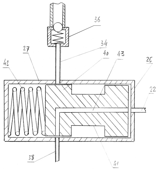
In conclusion, it should be noted that full justification parameters proposed two constructions automatic performance and the optimal value of the air pressure can be obtained only by a broad testing their efficiency in the bench and operating conditions.Analyzing the performance and device structures made of Patents and RU2402443 RU2399526 seen that all the same to them as to the prior art shown in Figure 1, Figure 2 and Figure 3, is inherent in an important drawback is that the adjustment of the drag forces is a step and consists of three phases characterize this process.Given this lack, we consider in our opinion a better automatic performance adaptive type, the design of which is recognized as the invention (RU2412844) and is quite different from the previous two, allowing smoothly and efficiently in the automatic mode, change the mode of freight train braking depending on the load of freight stock.Figure 7 shows a schematic diagram of the car brake rigging the device automatic performance adaptive type, and Fig.8 is one of its components in section.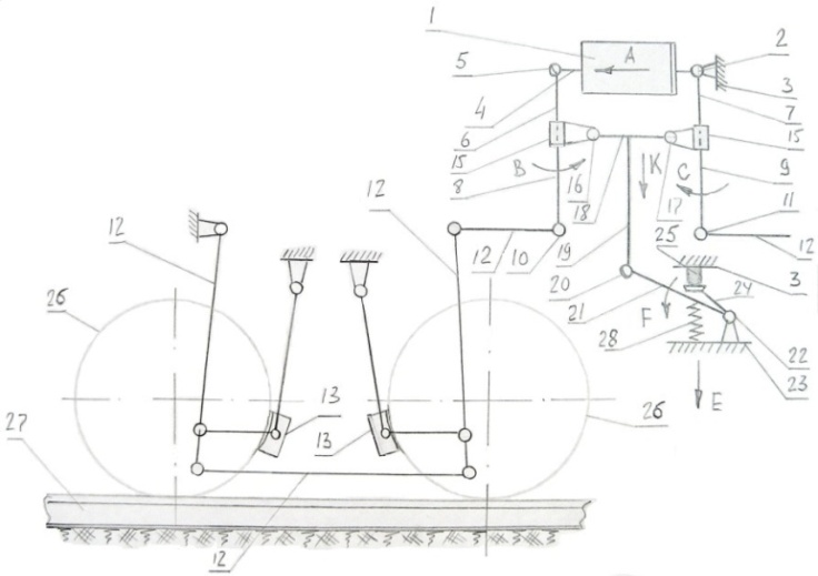 | Figure 7. Automatic performance is condition (patent RU2412844) |
 | Figure 8. Swivel thrust and lever |
In this case the brake rigging lever and the car, such as the brake load comprises a air brake cylinder 1 by a hinge pivot fixed to the frame 2 of the car body 3. The guide bar 4 of the brake cylinder 1 is provided with a hinge 5. By hinges 2 and 5 are connected to drive lever arm 6 and 7, and guided by their shoulders 8 and 9 are provided with hinges 10 and 11 to which are attached arms 12 controls insert 13. On top shoulders 6 and 7 and driven shoulders 8 and 9, the levers 14 are mounted movably channels crumbs 15 which via hinges 16 and 17 attached to rod 18. On rod 18 is rigidly fixed the rod 19 provided with a hinge 20, connected to bell crank arm 21 via a pivot 22 mounted on the sidewall of the trolley carriage 23. Another two-armed lever arm 24 by means of the heel 25 is pivotally connected to the frame of wagon 3. Brake pads 13 interact with the wheel pairs 26. Wheel sets 26 are mounted on the track 27. Double-armed lever arms 21 and 24 is provided with a compression spring 28.Powered brake rigging linkage of the car follows. When moving the carriage, for example, composed of a freight train, its structural elements of the transmission brake lever in such a state as shown in Figure 7. We also believe that the wagon is empty. In case the service brake of the train, including single wagon widely known manner fed under compressed air pressure the air brake cylinder 1 and its piston rod 4 when moving along the arrow A, acts on the driving arm 6 by rotating about the hinge 16 together with 15 biscuit slave arm 8 which moving the arrow to the levers through 12 promotes Preloaded brake pad 13 to the wheels wheelset 26, which thus provides braking trolley car. Simultaneously, a similar effect occurs with other trolley car (in Fig. She shown) the lever 12, which also acts on the leading and trailing shoulders of the arms 7 and 9 by rotating clockwise with respect to its hinge pivot 17 with its split key 15. Now consider the alternative braking of the car when it is fully loaded with cargo corresponding to its maximum payload. In this case, due to subsidence of the car body 3 by spring suspension (a suspension in Fig. Not shown), its 25 foot step, move the arrow E, and by acting on the shoulder 24, a two-armed lever, turn the arrow F its second arm 21, which leads to move the arrow to the rod 19. And since the latter is fixedly connected with a rod 18, then it is together with the hinges pivot 16 and 17 and, consequently, their split keys 15 moves in the same direction. This displacement rod 18 helps to change the length of arms 6, 8, 7 and 9, wherein the leading arms 6 and 7 are significantly longer in length slave arms 8 and 9. This change in length of these arms 10 allow the hinges pivot 11 and receive the forces transmitted arm 12, control of the insert 13 much larger in size, and thus create a more meaningfully greater braking force generated by insert 13. After unloading the car all the details of the described device returns to its original position as shown in Figure 7. It should be noted that the car body can not be loaded completely, the presence of the cargo it may vary within wide limits and, therefore, according to rod 18 can have a different position, thus changing the length of the arms 6 and 8, and 7 and 9 braking system that allows you to smoothly adjust the braking force to the inserts 13.Analyzing such a structure can be seen that it is very simple element base and its charge indicator is largely by the bell crank gear includes shoulders 21 and 24, the arm 24 contacts the foot step 25 pivotally connected to the wagon frame 3 (see Fig.7). It is known[7,9], the vertical displacement wagon frame does not exceed 48 mm and, therefore, the lever arm 24 will move a maximum depending on the amount of cargo in its body, while the stroke of the rod 19, 15 conveying biscuits should be about 120.0 mm, and then the gear ratio which includes a two-armed lever arms 21 and 24 must be equal to 2.5.
4. Conclusions
Based on the above, the following conclusions:1. The analysis of numerous bibliographic sources of domestic and foreign patents showed that modern freight and passenger cars, operates both in our country and abroad, have advanced braking equipment, but in spite of this within their structure the automatic performances has a complex structure and therefore in practice not reliable. Based on this analysis, we have developed at the level of inventions RU2402443, RU2399526, RU239525, RU2412074, RU2412844, RU2412843 design promising device eliminates these drawbacks, making the most effective use of them in the construction of railway rolling stock by automatically adjusting the air supply to the brake cylinders under certain pressure, affording required braking force to the brake shoes at different loading body of the latter.2. To determine the main design parameters of the proposed technical solutions developed calculation methods, one of which is tested on a four universal platform eight-wheel ton lifting capacity of 63.0 model 13-401. Calculations showed that for all modes of loading platform air pressure supplied to the air brake cylinder through the plunger automatic performance is constant and equal to 0,145 MPa but its weight loading of 50% and 100% the air brake cylinder through the valves 35 and 36 are, respectively, the air feed pressure largest 0,175 MPa and 0,255 MPa, that create therein a total pressure of 0.4 MPa and 0,320 MPa. Such pressures as a result and provide the necessary braking force to the axis of the wheel sets at the intermediate and fully loaded platform, respectively, equal to 4.8 m and 7.1 m, which is close to their normative values in the 5.0 t and 7.0 t. As a result, the use of such technical solutions will enhance the safety of trains and eliminate the possibility of accidents associated with the movement in their operating conditions.3. Results of the study submitted to the management of the Office of branch of JSC "Russian Railways" and the leadership Eletski center of Belgorod region UVJD to review the proposed designs for the auto mode of railway rolling stock and the ability to manufacture in the future layout and prototypes to test them as a bench, and operating conditions. At the same time, the design of the proposed devices are recommended to domestic and foreign investors, the scientific departments of JSC "Russian Railways" and the KB car building companies for their consideration, and possible improvements in the future of their implementation in practice.
References
| [1] | Rail: The Encyclopedia / Ch. Ed. N.S. Konarev. Moscow: Great Russian Encyclopedia, 1994. - 559 s.: Ill. |
| [2] | The design, analysis and design of locomotives. A textbook for university students. A. Kamaev etc. / Ed. A.A. Kamaeva. - M: Mechanical Engineering, 1981, 350p. |
| [3] | The design and dynamics of locomotives. / Ed. V.N. Ivanov. 2nd edition. - Moscow: Transport, 1974-335s. |
| [4] | Locomotives. Design theory and calculation. / Ed. N.I. Panova. - M: Mechanical Engineering. 1973 342s. |
| [5] | Improving the reliability of the vehicle-diesel / A.I. Belyaev, B.B. Bunin, etc. Under. Ed. L.K. Dobrynin - Moscow, Transport 1986123s. |
| [6] | Brake systems: Guide / M. Alexandrov et al, ed. M. Alexandrov. - M., Mechanical Engineering, 1985-264s. |
| [7] | Shaduro L.A., Shuttles II Wagons. M., "Transport", 1965 - 439 p. |
| [8] | Morozov II, S.S. Gamero All-metal and other passenger cars. Moscow Engineering, 1965 - 210. |
| [9] | Wagons. The design, theory and computation / ed. L.A. Shadura. Moscow: Transport, 1980 - 439 p. |
| [10] | The calculation of the strength coaches / Ed. L.A. Shadura. Moscow Engineering, 1978 - 432 p. |
| [11] | Vorshinsky S.V. and other dynamics of cars. Moscow: Transport, 1972 - 303 p. |
| [12] | Technical Reference railway. Volume 6. Rolling Stock. Ed. V.N. Sologubova. Gostranszheldorizdat. - M., 1952. - 955 p. |
| [13] | V.I. Krylov locomotive brakes - M. Transzheldorizdat, 1963. - 461 p. |
| [14] | Kazarinov A.V., Malikov N.V. On the classification of automatic parking brakes. Proceedings VNIIZhT, 2003.-32c |
| [15] | Nikitin G.B., Nazarov I.V., G.N. Gorunov The brake system platforms for large containers with a maximum speed of up to 140km / h VNIIZhT Proceedings, Vol. 16, 2006.-C34 |
| [16] | Patent RU 2255872. Brake trolley rail vehicle. Slivinskiy E.V., V.V. Teslin, Kurnosov O.V. |
| [17] | Patent RU 2232094 7V61N 11/02 Brake equipment railcar. Slivinskiy E.V., Shreds D.A. |
| [18] | Slivinskiy E.V., V.V. Teslin The study of kinematic parameters of a device for self-locking of the rolling stock with a computer. Computer science, concepts, current status and prospects for development. Proceedings of the scientific-methodological seminar. YSU them. Bunin. Elec, 2006 - page 38. |
| [19] | Gundareva E.P. Technical means of railways. Textbook. for technical schools and colleges rail. M. Route, 2003. |
| [20] | Patent SSSR № 11776 B65F 3/14, 1928. |
| [21] | SU № 1654151 А1, В65F 3/14, 07.06.91г. |
| [22] | French patent № 2433449, В61D 3/00, 1980г. |
| [23] | SU № 1768425 А1, В61D 35/00, 07.08.90г. |
| [24] | SU № 1654150 А1, В65F 3/14, 07.06.91г. |
| [25] | US № 5025719 А, 25.06.91г. |
| [26] | US № 3716184 А, 13.02.73г. |
 Abstract
 Reference
 Full-Text PDF
 Full-text HTML