-
Paper Information
- Next Paper
- Previous Paper
- Paper Submission
-
Journal Information
- About This Journal
- Editorial Board
- Current Issue
- Archive
- Author Guidelines
- Contact Us
International Journal of Traffic and Transportation Engineering
p-ISSN: 2325-0062 e-ISSN: 2325-0070
2014; 3(1): 8-19
doi:10.5923/j.ijtte.20140301.02
The Device Excluding Folding of Links of the Heavy-Load Road Train at Braking
 Abstract
 Reference
 Full-Text PDF
 Full-text HTML
E. V. Slivinsky1, S. Y. Radin2
1Prof., doctor of technical science, Mechanical Technological Faculty, Elets State University I.A. Bunin, Elets, 399770, Russia
2Associate prof., candidate of technical science, Mechanical Technological Faculty, Elets State University I.A. Bunin, Elets, 399770, Russia
Correspondence to: E. V. Slivinsky, Prof., doctor of technical science, Mechanical Technological Faculty, Elets State University I.A. Bunin, Elets, 399770, Russia.
| Email: |  |
Copyright © 2012 Scientific & Academic Publishing. All Rights Reserved.
This article presents the material relating to the development of advanced designs devices, excluding folding units train braking. In developing such technological solutions analyzed numerous, both domestic and foreign literature and patent sources allowed to create at 3 inventions efficient designs allowing to exclude folding units of heavy trucks when braking. On the basis of such devices developed computational scheme allows to assess the main rational kinematic and geometric parameters ensuring efficiency of the proposed design meets the requirements of the safety requirements of heavy trucks. The proposed development is recommended for both domestic and foreign research and industrial structures in the automotive industry for the purpose of further study and possible implementation in practice.
Keywords: Semi-trailer, Tractor, Saddle device, Spring, Boot, Pneumatic cylinder, Frame, Compound axis, Rigidity, Folding
Cite this paper: E. V. Slivinsky, S. Y. Radin, The Device Excluding Folding of Links of the Heavy-Load Road Train at Braking, International Journal of Traffic and Transportation Engineering, Vol. 3 No. 1, 2014, pp. 8-19. doi: 10.5923/j.ijtte.20140301.02.
1. Introduction
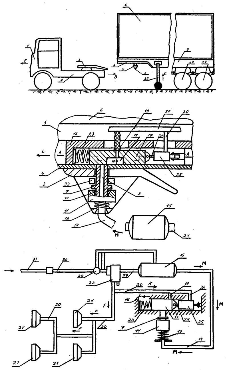
- One of the most effective ways to improve vehicle performance, quality and safety of transported goods, as well as reducing the cost of road transport is the use of articulated vehicles consisting of a tractor and trailer units, the main ones are the trailers and semi-trailers[1,2,3].Transport semi-trailers, both general and special purpose intended for the carriage of general, piece, bulk, liquid bulk cargo, as well as various agricultural products, and depending on the capacity of their perform uniaxial, biaxial, triaxial, etc. For the preparation of trains are equipped with the towing vehicle saddle device couplings, which are based on the ledges frame trailers. In addition, the units are equipped with terminals for connection of the brake system and electrical equipment for underwater towing vehicle systems.Fig. 1 shows a general view of train consisting of a towing vehicle and trailer used for transport of cargo[2]. It can be seen that the semi-trailer is a train link, which also performs the basic functions of the technological transportation process.
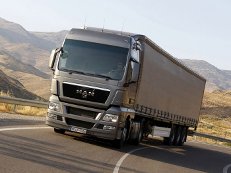 | Figure 1. General view of the heavy trains |
 and
and  . The resultant of all the forces exerted by the road on the vehicle wheel in the contact associated with the concept of road reaction which may be represented by three parts: normal Rz (it is the vector perpendicular to the road), the tangent Rx (its current vector in the plane of the road and the wheel plane ) and the transverse Ry in-plane perpendicular to the road wheel. The rotation of the wheel and move it on the road has also been associated with the concept of traction, which is determined depending on
  , where MT - the torque on the wheel of the engine, r - the radius of the wheel. On the driven wheel traction is not PT = 0. On the side of the road impede the movement of the wheel rolling resistance force
  and the resistance force of the road
  , where i - the slope of the road. Typically, the expression in parentheses is called the coefficient of resistance of the road and represent ψ, then
  , where G - the load on the wheel. In practical calculations to determine the nature of the vehicle at any time using the equation of the vehicle as follows:
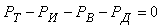 where: PИ - inertia, PИ = -ma;PB - aerodynamic drag force.It is also known[3] that the safety of vehicular movement is closely linked with its braking equipment. In the event of failure of the braking equipment car loses its stability, and as he continues to move, it is clear that the traction and braking its properties are closely related. If we consider the case of braking only when exposed to the brake system (engine braking is possible), then the equation of motion it will become:РТОР + РД – РИ = 0,or as a result, this equation can be written as:φх G + ψG – δврmаз=0,where, m - mass of the vehicle;φx - the coefficient of traction;ψ - the drag coefficient of the road;аз - acceleration deceleration of the vehicle;G - dead weight of the vehicle;δвр -factor has been rotating mass of a car.The most important parameters of a mode of braking are time of braking and a brake way which can be determined respectively by dependences:tтор=V / аз(мах) – 0,5 ty; Sтор= V2 / 2 аз(мах),where ty - time during which the deceleration increases from zero (start of the brakes) to a maximum value;V - speed at which there is a braking beginning.Even more adverse picture of movement is stability loss when braking road train. As usually when braking the trailer is rolled on the car – the tractor, in the coupling device there is pushing force directed in case of drift of any of two links of the road train at an angle ξ to its longitudinal axis. This force creates the additional moment developing the road train, bringing to its folding.It is known that kinematic and power interaction of links of road trains and transfer of traction effort to semi-trailers is carried out via the basic coupling devices which details are mounted both on the car - the tractor, and on the semi-trailer[2,15].Basic coupling devices are applied to transportation of semi-trailers and are devices which perceive not only longitudinal loadings, but also vertical from a body weight of semi-trailers, carrying out at the same time functions of the rotary mechanism.Under the influence of dynamic loadings in details of basic coupling devices there is considerable tension in size which carry as strength, and fatigue character. The valid nature of dynamic interaction of links of the road train depends on many circumstances, to consider which fully it is impossible. In this regard at analytical researches of power loading of basic coupling devices use a number of the assumptions, allowing to concretize and simplify the solution of an objective. So, for example, for studying of dynamic interaction of the tractor with the semi-trailer by Schukin M. M.[15] offered the settlement scheme (fig. 2) and the mathematical model of a look is developed:
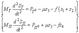 | (1) |
 and
and  - district traction forces on tractor and semi-trailer wheels;z1,z2,z4 - basic reactions on road train axes; z3 - vertical reaction in the basic coupling device;µ and f sliding friction respectively a coefficient in the basic coupling device and in a zone of contact of wheels the road.Analyzing the above it is visible that development of the technical means excluding folding of links of road trains at braking, and also calculation of their design data is an actual task.
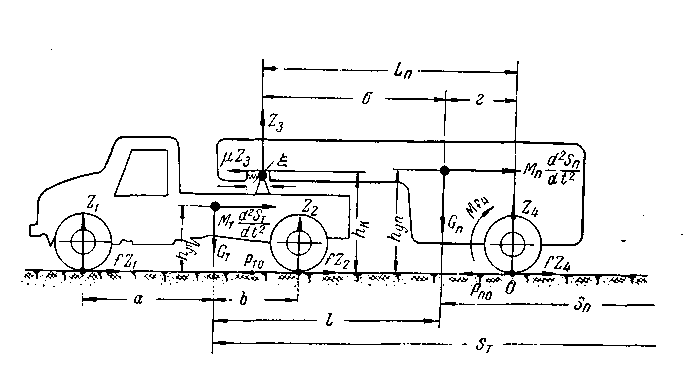 | Figure 2. Settlement scheme of the road train |
2. Research Objective
- Practice of operation of heavy-load road trains shows that the design of the last is still far from perfect, and especially it is shown in high accident rate on roads. Considering it, and also above-mentioned materials, the purposes and problems of this research are:1. Development of the perspective technical solutions, allowing to warn, and in some cases and to exclude folding of links of road trains at their braking, change of modes of movement, and also other unpredictable situations arising on roads.2. Development of design models and methods for calculating the structural parameters of devices linked to heavy articulated trucks.3. Development of the computer program, allowing to determine rational parameters of the devices increasing longitudinal stability of road trains of a various design and appointment.
3. Research Technique
- Given the above it in Elets State University I.A. Bunin for a number of years at the Department of Applied Mechanics and Engineering Graphics conducted research on "Dynamics, durability and reliability of transport, road-building and agricultural machinery, as well as industry-standard and non-standard equipment in relation to the Black Earth region of Russia" and one of its sections through the NIRS is a scientific field that is associated with the development of advanced technological solutions that increase driving stability trucks.The analysis of considerable number of bibliographic sources, and also domestic and foreign patents allowed to develop at the level of the invention the technical solution, allowing to prevent folding of links of the road train at its sharp braking (RU2368528).In fig. 3 the part of a longitudinal section of the road train in a sedelno-coupling device zone in the vertical plane and in fig. 4 a view of the sedelno-coupling device from above is shown.
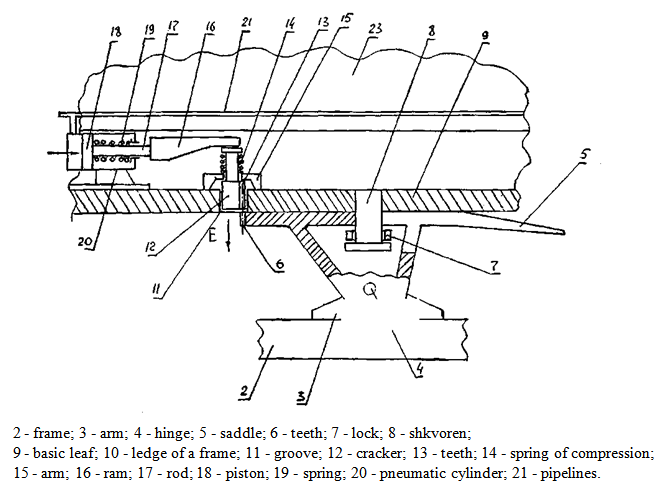 | Figure 3. Longitudinal section of the road train in a sedelno-coupling device zone |
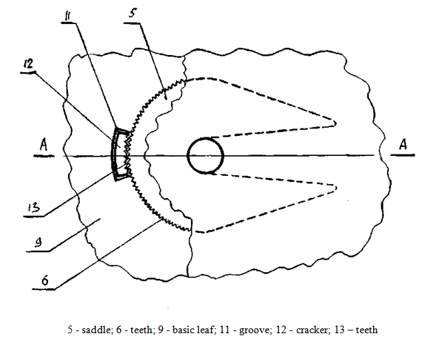 | Figure 4. Sedelno-coupling device top view |
 the mass of the semi-trailer and
  mass of the car tractor is developed for calculation of the key kinematic and geometrical parameters of the offered device.
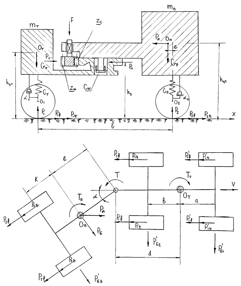 | Figure 5. Settlement scheme of the road train |
 and
and  on back wheels of the car tractor there will be a reaction
  , and on semi-trailer wheels –
 . The specified masses are connected among themselves shkvorny with flexural rigidity
  and the last is rigidly fixed on a semi-trailer frame. On a semi-trailer frame, movably in its vertical plane the gear Zш, boot interconnected with gear sector Zc executed on a saddle of the saddle device of the tractor is established. To a gear boot force F created by the mechanism of its management located on a trailer frame is applied. Reactions of communications
  and
and  are attached to weight
  and, operating on shkvoren in the horizontal plane located at height
  from the plane of the road. When braking road train to the center of gravity of the semi-trailer inertial force
  is applied, and in a zone of contact of wheels with the road arise from friction force
  and braking force
  . The centers of gravity Оп and От of masses
  and
and  also are located respectively at height
  and
and  from a road surface. It is obvious that vertical reactions
  and
and  can be determined by dependences[3]:
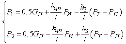 Analyzing the system of equations, it is clear that if
  and
and  , then their influence on the redistribution of loads on the wheels of the towing vehicle and trailer, if
  then
then  (
( can be positive or negative) then the run-up to the semi-trailer tractor units stretching or train. At the same time, it is clear that such a redistribution of loads is significantly affected by the magnitude
  and its relation
  with the greater the ratio, the wider the scope of congestion fifth-wheel towing vehicle and drive wheels. This phenomenon helps to block the rear wheels of the towing vehicle when braking[2,3]. In order to take into account the damping force train
  , project the horizontal components of the forces on the axis XX, and then the equation of motion becomes:
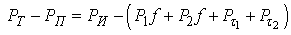 Assuming that
  and
and  , can be calculated according to the force of inertia:
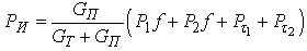 .Determining the force of inertia can be calculated toothing on the strength of the stabilizing device. Here is an example of such a criterion for calculating road train consisting of a towing vehicle MAZ-5432 total weight
  = 7050 kg and a car trailer container truck MAZ-9397 model with
  = 26800 kg. At the same time as the initial data we adopt the following measures using the data of[1].
 - distance from the road surface to the center of mass of the towing vehicle, 1,2 m;
 - distance from the road surface to the center of gravity of the semitrailer, 1,8 m;
 - distance from the road surface to the horizontal plane of the longitudinal forces
  and
and  ;
; - distance from center of gravity of the semitrailer to the vertical symmetry axis of the rear wheels of the semitrailer suspension, 3,2 m;
 - static vertical reaction to the rear wheels of the tractor trailer 88000 N and from the tractor 24400 N,
  = 88000 + 24400 = 112400 N;
 - static vertical reaction of rear-wheel trailer, P2 = 180000 N;
 - rolling resistance rear wheels truck
  = 11240 ∙ 0,02 = 2248 N;
 - rolling resistance wheels of the semitrailer
  = 18000 ∙ 0,02 = 3600 N.Suppose[2,3] that the inhibition occurs when trains its speed of 40 km/h (such a velocity is set to GOST 22895-77 Limits vehicle braking distance), the braking force and
  will be equal
 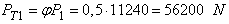 and
and 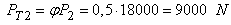 , where
  the coefficient traction is assumed to be 0,5[3] when moving train on dry roads with asphalt concrete pavement. Then the force of inertia
  is determined by:
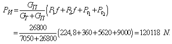 We compute for a given force
 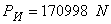 acceleration deceleration
 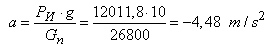 .Then the stopping distance trains will be:
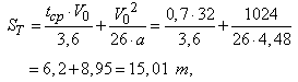 where
where  - the brake actuator response time
  [3].It is known[ 2,3 ] that the stability of the motion train evaluated from the size of the critical speed, which , in practice , in the case of the semi-trailer skidding when braking is quite low and averages
  . When braking force acting in the plane of the road are large and at the same time are different in magnitude for each of the wheels, in this case a turning moment which causes a reversal in semi heading angle ψ. Since in our example, made the speed of movement
  , it is possible for instability when braking trains. Therefore, to ensure reliable stabilization of the semi-trailer towing vehicle relative to define the torque T arising in connection gear when subjected to forces of inertia
  = 120118 N braking trains. We use the recommendations in[3], according to which in accordance with GOST 22895-77 in order to ensure the safety of folding angle α trailer braking must not exceed 150, therefore, РБ lateral force applied to the center of gravity of the ОП (Fig. 5) in this case is equal to РБ = РИ cos(900-α) = 12011,8· cos750 = 12011,8·0,2588 = 31086 N. Given that the distance between the center of gravity of the semi-trailer to the teeth , according to the nameplate data on the semi-trailer models MAZ - 9397 is 9350 mm[1] torque of the tooth will be Т = РБ ·е = 3108,6·9,350 = 290654 N·m. We define a module gearing the known dependence of the strength condition of the teeth in bending:
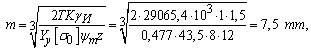 where K - coefficient taking into account the conditions of the transfer;γи – coefficient taking into account the dust and corrosive environment;Yу - the shape factor of the tooth;[σ0] - flexural endurance limit;Analyzing the above it is clear that the practice of folding units can train at its various speeds ranging from 20 km/h or more and actions on the brake forces are in a very wide range. On this basis in order to enhance the operational capabilities of the proposed device, which eliminates folding, filling the air cylinder control locking device cooperating with a toothed sector performed in the seat of the saddle device of the truck must be carried out as quickly as possible to engage the teeth occurred at angles of rotation of the semi-trailer is not greater than 50. Therefore it is constructive choose a small inner diameter, for example equal to 30 mm. At the same time, for the rational selection of the geometric characteristics of the air cylinder requires a wide range of testing full-scale models in operational conditions, and only then finally justify the optimal geometric and kinematic settings for each train consisting of different models of trucks and automobile trailers.At the same time, the analysis of a large number of bibliographic sources, as well as domestic and foreign patents (RU2009932, SU1169872, DE4429986, WO90/03297, SU1172811, SU1230911, US5620195, RU2175927, US3825089, etc.) led to the development of inventions at a number of technical solutions, help prevent folding units train when braking (RU2255018, RU2254246, RU2255017). Let us consider the design of such devices attached to trucks.So Pat RU2255018 described heavy-truck (Fig. 6), consisting of a tractor 1, in frame 2 is fixed saddle device 3. Saddle device 3 is interconnected with pivot 4, and lockable lock 5 slidably disposed in the longitudinal groove 6 formed in the supporting plate 7 and frame 8 of semi-trailer 9. Pivot 4 is connected via hinge 10 with the cylinder 11 and its rod 12 as by a hinge 13 fixed to the frame 8 of the semi-trailer 9. The cylinder 1 via a conduit 14 connected to conduit 15, the feed brake cylinders 16 of wheels 17 of semi-trailer 9. In the groove 6 between the frame 8 and the pivot 4 is placed a compression spring 18 and the rod 12 is provided with a piston 19.When driving train according to arrow B, and its abrupt deceleration occurs folding trailer 9 relative to the towing vehicle 1 as shown in Figure 6, but the proposed design does not happen for the following reason. As soon as the driver of the tractor 1 will make a sharp slowdown, semitrailer tractor 9 will have one as the longitudinal force inertial force P applied and the angular momentum M, caused, for example, uneven brake force applied to the braking devices of wheels 17 semitrailer 9, the influence of micro Profile the road, the difference tire pressure wheels 17, etc. At this time, under the action of the force P pivot 4 moves to the groove 6 by the arrow C, elastically deforming the compression spring 18 while pulling the rotation into the same cylinder 11. Since the conduit 15, a pressure air (such trailer braking process is widely known in the art), exerted by the arrow Д to the brake chamber 16 and the cylinder 1 moves in the arrow C, then at a certain time due to immobility rod 12 and therefore and the piston 19, the latter blocked by conduit 14 (as shown in Figure 6) engages with the left cylinder space above the piston 11 and the compressed air from conduit 15 enters this said cavity. At this time, the compression spring 18 is fully compressed and then the compressed air piston 19 will move together with the rod 12 by the arrow E, as well as the rod 13 is connected to frame 8 of semitrailer 9, the latter will move into the same direction. This movement promotes the trailer of 'waste' it from the towing vehicle 1 in the direction opposite to the movement of trains, which will create conditions for reducing torque M as the wheels 17 inhibited their brake chambers 16 as a "stretched" road train , and, consequently , the rotation angle α of semitrailer 9 relative to the tractor 1 significantly reduced. Once the truck stops the movement and the driver will translate the tractor brake release mode, the pipeline 15 is connected to the atmosphere (such a process is also well known in the art), and in the left cylinder chamber 11, the pressure will disappear. Once this occurs, cylinder 11 begins to move under the action of a spring 18 according to arrow F, as well as brake chamber 16 is also connected with the atmosphere and the trailer wheels 17 disinhibited were then semi 9 moving on wheels 17 return to the original position. Such a phenomenon will occur in cases where a sharp braking or emergency train will occur at the location of the tractor 1 and semitrailer 9 on one longitudinal axis of symmetry, i.e. when angle α = 0. In this case, the longitudinal stresses resulting from exposure tractor 1 to the semitrailer 9 will be damped as a compression spring 18 and the cylinder 11, as was the case in describing the operation of the apparatus above.
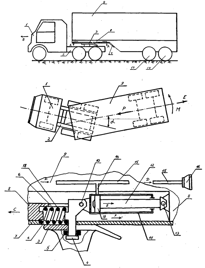 | Figure 6. The device according to the patent RU2255018 the excluding folding of links of the road train when braking |
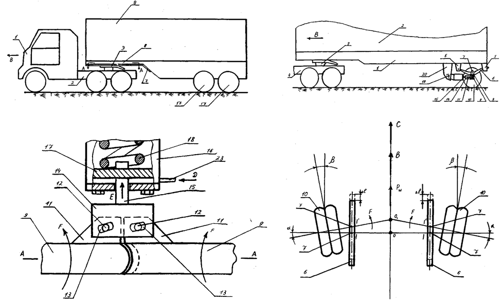 | Figure 7. The device according to the patent RU2554246 the excluding folding of links of the road train when braking |
 | Figure 8. The device according to the patent RU2255017 the excluding folding of links of the road train when braking |
4. Results
- Based on the above, the following conclusions and suggestions:1. The analysis of both domestic and foreign construction trucks shows that the latter have a significant disadvantage that in case of sudden braking or service at different speeds, they have a high ability to folding. This phenomenon is dangerous not only for the trains, but also for other vehicles moving after him or meet him. Experience in operation of motor trains shows that the consequences of accidents that occur on the roads for this reason, make up more than 5% of all accidents recorded by the world practice.2. Given the above us on the level of inventions (RU2255017, RU2254246, RU2255018) developed technical solutions devices allowing prevent folding units trains when they move at different speeds and in particular when they are exploited in the autumn and winter time.3. To establish a rational geometric and kinematic parameters of one of these devices developed a physical model and proposed a method for their calculation. Thus, our calculations as applied to train consisting of car MAZ-6422 trailer and container models MAZ-9389, showed that as the elastic coupling can be used compression spring made of steel bar Steel 602S 22mm diameter with a work force and rigidity, working together with the pneumatic cylinder. To automate the calculations developed a computer program in the language of Delphi, which allows to calculate these parameters for different designs trains.4. Results of the study are recommended for domestic and foreign transport companies, automobile industry, science and engineering, both domestic and foreign entities operating in the automotive industry for the study and analysis of the proposed designs for possible further put them into practice.