Е. V. Slivinskiy, S. YU. Radin, Т. Е. Mitina, I. N. Gridchina
Yelets State University, I.A. Bunin, Russia
Correspondence to: Е. V. Slivinskiy, Yelets State University, I.A. Bunin, Russia.
| Email: |  |
Copyright © 2012 Scientific & Academic Publishing. All Rights Reserved.
Abstract
This article presents information on the development of advanced device structures for the antifriction of crest castor of locomotives and wagons triggered automatically when the passage of rolling stock parts are crooked ways and in the end that reduce the wear of crest castor of wheelpairs. Grounded goals and objectives of the study and based on an analysis of numerous domestic and foreign literature and patent sources on this problem have been proposed as inventions such devices are used for antifriction of crest castors not only wheelpairs, but also the side tramway head surface liquid, plastic and graphite antifrictions. The methods of calculation, developed the physical and mathematical models to determine the basic geometric and kinematic parameters of the above structures. Results of the study recommended research and industrial structures in the area of car building heavy machinery to further study and possible implementation in practice.
Keywords:
Bow, Bogie, Whellpair, Crest, Castor, Antifriction, Kinematic Coefficient of Viscosity, Rotational Speed, Side Force, Tramway
Cite this paper: Е. V. Slivinskiy, S. YU. Radin, Т. Е. Mitina, I. N. Gridchina, By the Operation Reliability of Wheelpair of Railway Rolling Stock, International Journal of Traffic and Transportation Engineering, Vol. 2 No. 5, 2013, pp. 106-119. doi: 10.5923/j.ijtte.20130205.03.
1. Introduction
Locomotive wheelpairs (Fig. 1), passenger and freight cars (Fig. 2) are one of the known elements of their vehicle-parts and wheelpairs them consist of wristpins and castors - solid or teams. Prefabricated castor consists of a center brace and split rings. Bandages and solid-rolled castors with tread and longitudinal crests. The castors are made of steel (Steel 25l - III according to GOST 977 - 75), and the bands of open-hearth steel AK 60 - III according to GOST 398 - 71. Locomotives and wagons, moving on straight sections of road, in fact, describe not straight, but a complex wave -like trajectory.In this case, the motion along the way they move across it but still get the angular rotation around the vertical axis. Such a complex movement is called the winding[1-4,6-9]. In the course of this movement occurs in cars considerable inertia, creating a lateral pressure of crest castors on the rails, due to their natural deterioration. At the same time, the cars at the entrance to the curve path described by a twisting motion, the dynamic loads on the of crest castors on the rails further increase, which contributes to a substantial largest friction, which also reduces the longevity of crest castors. Such wear of ridges crests significant financial and human costs of premature repairs undercarriage of cars and replacing worn tramways. The practice is replete with such examples. So, for example,[10,11] on the Trans-Baikal Road in 1985, an average of locomotives stood on refacing bandages after a run of 35-40 thousand km. To increase the mileage was proposed firstly operated wheelpairs crest thickness up to 23 mm and, secondly, apply the antifriction on locomotives crests. However, the first sentence does not solve the problems of wear crests, as at higher speeds there is a danger of their cleavage. In the latter cases for more than 15 years of debate on the use of devices that provide a supply of liquid or grease in the area of friction crest and the rail head, and practical application to date they have not been found. Analysis of the financial performance of the locomotive depot station. Elec UVJD, we carried out in 2007 showed that the wear of crest castors locomotives operated by the department after Eletsky run locomotives 200-250 thousand km more than the normative value that the recommendations of the IPU is 400 thousand kilometers. In many countries, the issues antifriction of crest castors, selection grade antifriction and development of modern means of applying them paid much attention. For example, the German railways are losing significant losses from wear of rails and of crest castors. Every year is to replace about 20% or 100 thousand tons of rails and about 60% of the costs spent on turning of the tires and the restoration of their profile associated with the wear of crest castors. As in the previous case, the operating staff concluded that reduction of production costs and losses of wear of the rails and ties wheels importance is the application of antifriction. It should be noted that not every antifriction can provide to eliminate the above drawbacks and therefore must meet the following requirements: the antifriction should possess high viscosity to have a high adhesion to wet the tracks and does not emulsify with water. The antifriction must act only on the side surface of the head rail lubricating device should be simple in design and provide antifriction of the automatic mode only when the passage of the rolling stock in the curve path, the antifriction can be applied to the crests of the wheel and a stationary device disposed on stages and station tracks .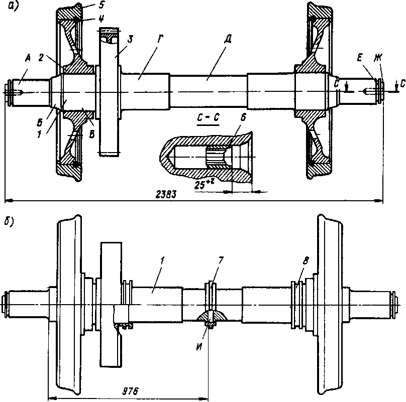 | Figure 1. Wheelpair locomotive |
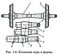 | Figure 2. Wheelpair wagon |
In assessing the wear crests wheelpairs and the tramways heads in addition to considering the values of the lateral force in practice, take into account the optimal profile bandages castors and yaw angle of the crest on the head tramways. Research results[3] showed that the use of the profile machined operation promotes more intensive bands crests and tramways wear. This implies that the rolling stock must change the profile of the shroud so that the beginning of his work could take place single contact, a spot which is common for both rolling circle and for the crest. The analysis above shows that still one of the important areas in terms of reduced wear of castor crests of locomotives and wagons is their antifriction, and feed it into the friction zone should occur with devices operating in automatic mode and excluding hit her on the running surface of the castors and cluttering sleeper cell and its ballast.In conducting RW and RWS in this area at YSU name I.A. Bunin been studied numerous references, as well as domestic and foreign patent sources, on the basis of which were developed at the level of inventions (RU2236364, RU2236362, RU2236363, RU2236361, RU2238207, RU2238206 etc.) promising technical solutions to supply a liquid or grease on crest castors of the rolling stock at the time of his movements in the curved sections of track. Despite their efficiency, they all have significant disadvantages in that they can be installed mainly in locomotives, where they can be refilled periodically antifriction working station and depot, carry out the necessary examinations with the elimination of identified defects, etc. At the same time, when applying antifrictoin to crest castors and transfer it in the last area of friction is inevitable part of it will fall on the structural elements of the railway, in the future, as the accumulation of it, is the source of their littering Purification of the items on a time-consuming operation and currently can not be mechanized Such work may be carried out either with the driver helpers or team of fitters on equipping items locomotive depot. But installing such devices on the cars and especially trucks, the number of which is very significant, and therefore not economically feasible for this type of rolling stock should probably have other devices.
2. The Purpose of the Study
Given the importance of the problem aimed at improving the operational reliability of the castors of wheelpairs of freight and passenger cars using solid antifriction, the purpose of this study is:1. Development of the devices for feeding solid antifriction when passing cars ready path sections in the area of friction-castor crest tramway head. 2. Development of the design scheme of the device allowing to make calculations to determine its kinematic and geometric its parameters.3. The use of a computer program that takes into account the diversity of structures of passenger and freight cars, and allows the calculation of parameters of the proposed design of hardware components.
3. Method of Research
Consider, for example, a device for of castor crests antifriction applied to railway freight cars and freight cars and industrial vehicles using solid antifriction recognized invention (RU2344956).Figure 3 shows a portion of the freight car side view, and as part of its cross-sectional plane AA.Freight car body consists of one mounted on the bolster 2, which with the help of spring sets located in apertures 3 4 5 sidewalls carts. In sidewalls 5 posted with wheel axle box 6 pairs consisting of the castors 7 crested 8. On the sidewalls 5 rigidly fixed cylinders 9, 10 rods which are fitted with skids 11 containing a solid lubricant (TCM). Cylinders 9 via piping 12 connected with the air slide valve distributor device 13, which is rigidly secured to the bogie beam 2 and its spool 14 is provided with a lever 15 located in the plug 16 attached to the bottom frame rail 17 of the vehicle. To the distribution spool air apparatus 13 connected as conduit 18 which is connected with a reserve tank 19 air brake system of a rail vehicle.Powered rail vehicle follows. When it enters a curve path trolley with side walls 5 and the wheepairs of angular rotation is, for example, clockwise with respect to the body 1. This facilitates rotation of angular rotation relative to the casing spool 14 pnevmoraspredelitelnogo spool device 13 due to the fact that its arm 15 is located in the fork 16 fixed to the underbody 17. As soon as a corner turn the spool 14, the last line 18 connects to the piping 12 and the compressed air from the storage tank to go on air cylinders 9. Under the action of pressure cylinders 9 rods 10 will move along the arrows C, which ensure contact of the solid lubricant present in shoes 11 with crests 8 wheelpairs the castors 7. Damage layer SCI crests 8 castors 7 go into the zone of friction with the tramways head, and that will reduce the force of friction occurring in the area of kinematic pairs of castor-tramway. After passing through the curve path and exit the car on straight portion 14, air distribution valve spool device 13 returns to its original position, closes the conduit 18 and connects conduit 12 to atmosphere, allowing movement of the rod 10 in a direction opposite arrows C under the influence of the compression springs located in the pneumatic cylinders their subpiston chamber (single-acting pneumatic structure is widely known in practice, for example, this principle brake cylinders arranged rail vehicles). Movement of rod 10 in the direction contributes to sail shoes 11 in the same direction of crests 8 and castors7 antifriction their stops. Further described processes can be repeated many times.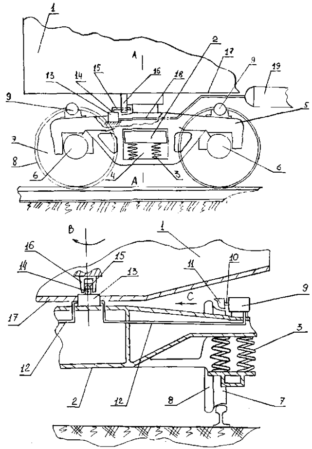 | Figure 3. Promising device for lubrication of castor crests wagons |
Consider the loading force of the castor crest wheelpairs in its point of contact with the tramway, and by reacting 4 stone using the calculation scheme shown in Fig.4, when the truck enters a curve the carriage path.We believe that the castor has an angular velocity ω while moving along the tramway 2 and the castor itself is rigidly secured to the axle 3. Under the influence of its own weight of the laden weight mв is applied to the castor load G, which causes the normal reaction N, occurring at the contact castor 1 on with the tramway 2 contact patch area Sк. At the point O, the castors 1 in contact with the tramway 2 friction arises  When the castors in motion path curve generated lateral force contribution Ур, which can be defined as the average Ур = 0,6G. In addressing the curve of the road to the crest of the castor will be adjacent stone 4 under the force Pк, generated by air pressure from the storage tank air brake system of the car, and then at the point of contact with its crest castors arise adhesion-friction
  under the influence of which on the surface of the crest will be applied a thin layer solid antifriction, the latter will come in the future in the area of the contact point O of the castor crest and the tramway. Selection of the solid lubricant device for antifriction of castor crests of the car whose design described above is produced, for example, with respect to 4-gon osnomu all-metal carrying capacity 60,0 т, container 26,5т. Consequently, the load on the y-axis of the gondola will be
 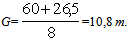 It is known that when entering a curve in the road gondola lateral force Ур, created crest, wheels on the tramway head is on average 60% of the vertical component of G acting on the castor, i.e. Ур=0,6G=0,6∙10,8 =6,5 т. It is known that in the contact area of the castor crest with the side surface of the tramway head and the disk driving it with its horizontal surface there is a bonding pad, the shape close to an ellipse, a total area Sк=0,0011 м2. Therefore, the contact area attributable to castor crest on average Sк = 0,5∙ 0,0011=0,00055 м2. Define an average value of the specific load in the contact zone
 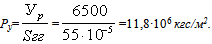 Assume that the speed of the gondola, located in the freight train is Vв=80 км/ч = 22,2 м/с, then the castor speed to determine
 when dk diameter of the castor rolling circle.
 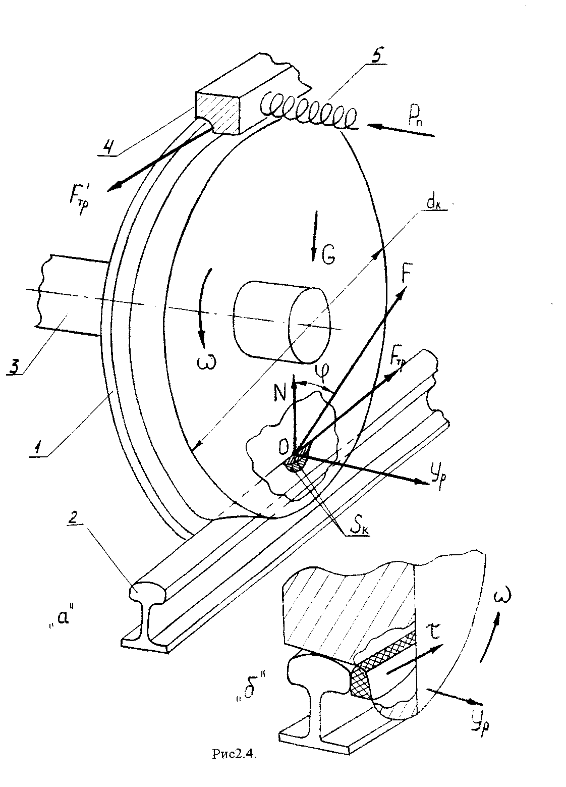 | Figure 4. Design scheme |
We define the angular velocity of the the castor . According to the theory of friction F. Bowden and D. Taylor, in assessing the carrying capacity of solid lubricants in heavy-duty kinematic pairs[22] believe that the entire lateral load Ур perceived crest castor and SCI layer entering the zone of contact with the side tramway head undergoes plastic shear in this case, the friction coefficient can be determined according to
 wherein
 when:
when:  – shear resistance of the solid lubricant;Ру - specific load in the contact area of the castor crest of the tramway head to,11,8∙106кгс/м2;К1 – the proportionality factor is equal to 2;n – exponent, 0,3. Then the coefficient of friction is equal to:
 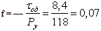 .The obtained value of the coefficient of friction of 0,07 at the value Ру = 188 МПа corresponds to the solid lubricant; pure graphite in a test Bridgman. Graphite is a natural material, has a hexagonal crystal lattice formed by a series of parallel layers (basal planes) consisting of carbon atoms with high binding energy at lower energies between the basal plane. It has high anti-friction properties. Its physical and mechanical properties of the following - the parameters of the crystal lattice, 10-6 мм – а=1,42; с=3,25;
  ; density 2,1∙103кг/м3; elastic modulus 5050МПа; temperature oxidation 6730 К and the decomposition temperature 37730 К.To selected solid lubricant has successfully worked in the area of the friction castor crest to the head tramway, it must be delivered there. To do this, the stone 4 should be made such an effort Рп, microrelief which would fill of the castor crest contact surface, if the effort to select the significant value, there will occur an excessive flow FCM if slight, it will wear as a crest and the tramway head. Using the recommendations of[22] by the pressure, causing the onset of deformation of graphite by the empirical relationship:
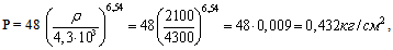 где: ρ – density graphite. Taking constructive contact area of stone with dimensions of 4
  with the surface of the castor crest, equal Sк = 2,0∙8,0 = =16 см2, efforts to define the desired value Рп, which must be created with compressed air via a pressure regulator,
  The most important indicator of the castor crest coupling with stone 4 lubricating device is the wear rate of the SCI, which will depend on the type of fracture of the surface layers of graphite. To characterize the wear process of stone commonly used integrated linear wear rate Ih, which essentially depends on the mechanical properties of the castor material and TSM, and the species, strain in their surface layers. Due to the fact that the elastic modulus of the steel castor manufactured which is considerably higher than that of graphite, it seems that the latter would deteriorate more rapidly. We use the dependence on the definition of durability FCM derived for flat sliding bearings[22]:
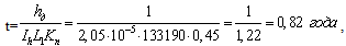
 – allowable thickness of the graphite layer is worn stone 1,0мм;L1 – friction path per unit time,
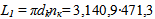
 Кn – utilization of the freight car in motion on curved sections of track and offices for Eletski UVJD the area Elec-Leo Tolstoy, shoulder 112 км, is assumed to be 0,45;Ih - the wear rate, which in our example can be determined according to
  , when:
  ;Vп – the volume of worn material
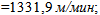
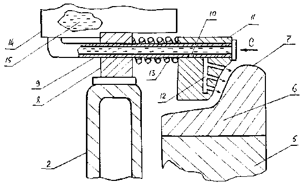
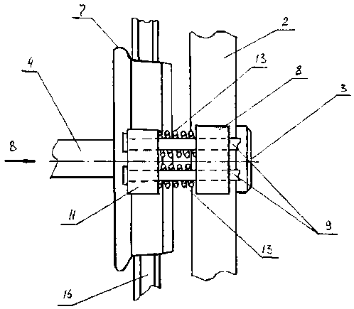
  Vп=1,6 см3.From the presented calculation shows that the operation of freight cars, for example, in the section Elec-Leo Tolstoy UVJD solid antifriction will last for life t = 0,82 year.Later, after the wear and tear of such antifriction, you can restore it by removing the worn stone for a new device, as in a train depot and forces osmotrschikov cars on the respective stations. It should be noted that under operating conditions in all wagons road network areas RF durability TCM employed in the described apparatus will be different and therefore in the case of the proposed structure for antifriction castor crests must be enlarged to calculations, the performance test bench and it that eventually will develop an optimal design that satisfies all of the freight car fleet in the country.Consider now the device (RU2373090) is a very simple design, which is shown in Figure 5, Figure 6 and Figure 7.This design can be mounted on trucks domestic and modern locomotives TEP70, TEP80, 2TE121, 2TE126, TE136, as well as foreign models such as, for example, freight locomotives British Rail Class 60 and Class 121 diesel locomotive firm "Kolmeks" type 302D Polish railways, etc., and it can operate on both liquid and grease. Thus in Figure 5 shows a perspective view of a side section of the locomotive on the enlarged part of Figure 6 assembly taken along A-A of the locomotive at the junction of one of the castors to the frame and in Figure 7 like assembly view according to arrow A.
 | Figure 5. A general view of the section of the locomotive |
 | Figure 6. Side view of a device for antifriction of castor crests |
 | Figure 7. Top view of the device for lubricating of castor crests |
The section consists of a locomotive body 1, located on the carriage 2. Carriage 2 is provided with a journal box 3, which has the axis 4 of castors 5 provided with tires of ridges 6 7. The frame 2 is located bracket 8, wherein the fixed hollow rods 9 provided with holes 10.In the hollow rods 9 slidably mounted cotter 11 with vertical channels 12, the latter being spring loaded compression springs 13 relative to the bracket 8. Hollow rods 9 are connected with the container 14 in which antifriction is 15. The section of the locomotive moves along the track 16.Powered device for antifriction castor crests of the locomotive wheel pairs as follows. In the case where the section moves along the straight portion of the path 11 is positioned relative cotter 7 crest band gap 6 as illustrated in Fig.2. On entering a curve section locomotive castor track section 16 with shroud castor 5 6, the crest 7 and the axis of 4 is moved in the axial direction, such as arrow B. This movement ensures that the crest 7 is in contact with the biscuit 11 and moves it in direction C, compressing the compression spring 13. Finally, the movement of biscuit 11 reaches a position where the opening 10 of hollow rods 9 coincide with the vertical channels 12, made in the Rusk 11 and, then antifriction 15 (grease is better to choose plastic, although you can fill the tank 14 and the liquid) goes on the friction zone cracker 11 and the crest 7 , which will reduce the wear and tear of the kinematic mating pair. If a section of the locomotive is stopped at the curve section of the path on various technical or organizational reasons, the outflow of antifriction 15 or expense will be eliminated by a relatively snug fit biscuit 11 to the castor crest 7, compressing the springs 13. After the passage of the locomotive section of the curve track section 16 wheel 5 with a bandage 6, 7 and _ axis 4 returns to its original position, moving in the opposite direction B, with the result that rusk 11 in the position shown in the figure as well as the opening 10 and Channels 12 are displaced relative to each other, the expiry of the _ antifriction 15 biscuit 11 stops. Further described processes can be repeated many times.Selecting lubricant for such devices is made, for example, applied to diesel locomotive TEP60, which is the axle load 211 кН. This lateral force Ур when entering a curve in the path of the locomotive, power 0,6·П, when П — load, attributable to each castor wheelpairs. Then Ур = 0,6·105,5 = 63 кН = 6,3 т. To study the nature of the loading of the lubricating layer in this area, developed the design scheme, which is a locomotive castor which rolls along the tramway under the influence of torque Мк. It is known that in the zone of contact of the castor crest with the side surface of the rail head and the contact zone of its rolling circle with it also the contact area is close in shape to an ellipse, a total area Sk = 0,0011 м2. Therefore, the contact area attributable to castor crest, the average amount  Define specific load in this area:
 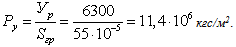 We believe that the speed of the locomotive during the passage of the curve path is
  then the castor speed is determined:
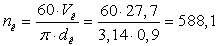
 when dк = 900 мм.We now define the angular velocity of the castor depending on:
 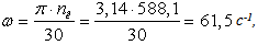 that allows to calculate the lowest dynamic viscosity of the liquid lubricant from the formula:
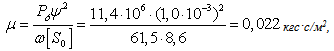 When, Ру - average unit load in the friction zone, which is equal
  ψ - the relative gap between crest castors and the tramway, equal to 1,0·10-3 мм;ω — the angular velocity of the castor, which is equal to 61,5 с-1;[S0] — dimensionless criteria equal to 8,6 and depends on impeller diameter and width of the pad in the friction zone.We now define a corresponding kinematic viscosity of the liquid antifriction to the relationship:
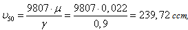 when: γ — the proportion of antifriction is assumed to be
  For a given υ choose from reference industrial oil-H-E 220 GOST 17479,4-87 kinematic viscosity υ50 = 242 сст at a temperature in the friction zone 50℃. Now we calculate the proper lubrication
  flowing from the conduit and onto castor crest at the entrance to a curve of the locomotive at the time when the impeller is rotating, and generates an overpressure in the pipe P according to:
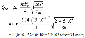 when: μr— expense ratio is equal 0,62;d— diameter of the outlet pipe, 1,5 мм;ΔP — the pressure generated by the impeller equal 4,5
  ρ — density of the lubricant, which is equal to
 .Now we calculate the velocity of the antifriction from the pipeline:
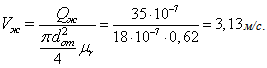 From the above calculation shows that the speed of the locomotive
  in its second castor makes 9.8 revolutions path passing around 28 meters, hence its groove in such a time interval is applied on average 35 grams. lubricants, which are distributed across the the crest forming a uniform layer that is sufficient to reduce the coefficient of friction in the contact zone, the head tramway groove. Thus, if the curve is the average path 1000м and the time of its passage is about 35 seconds, then this section will be spent around
  antifriction. Given the diversity of types of locomotives, a small portion of which is depicted above, and hence different characteristics of
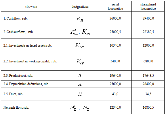
  an axle load, etc., as well as the complexity of calculation parameters μ and ν necessary in each case to choose the appropriate type of antifriction, developed a computer program using the language of Delphi, to automate the calculations and obtain the necessary data for the design of the device in relation to each particular model of the locomotive or locomotive.For the economic evaluation of the development of a technique used by the financial and investment analysis and audit of the introduction of new technology[25]. Here is an example of determining the value of the projected cash flows for the modernization of the locomotive 2TE10L assigned to the locomotive depot Elec UVJD when installing it proposed technical solutions. For this we use the reference data presented in Table 1, which are characterized by cash flows in the manufacture of the proposed device for of castor crests antifriction of wheelpairs with conceptual design, developed by the Department of PMiIG YSU name. I.A. Bunin in 2011, according to research carried out by order of technical management policy UVJD JSC "Russian Railways".Analyzing the data table shows that the increase in investment provides the least dependence of the locomotive depot of supplies of materials and semi-finished products in the design and implementation of a device for antifriction of castor crests into production.The increase in cash flows associated with the modernization affects the amount of tax reduction, which decreased by (43,0-34,5 = 8,5) 8,5 rub. First of all, this is due to the decrease of the tax base, while increasing the rate of return on 30%. Reducing the cost in this case possible to reduce, in general, the amount of tax.It should also be noted that as a result of reducing the cost of manufacturing the device for long-term antifriction of castor crests of the locomotive was possible to increase the amount of cash receipts by increasing the rate of return of about 30%, not increasing production capacity. In addition, to determine the yield (efficiency) innovate, you can also use a number of indicators:So to reflect the difference between the future and the present value of economic practice, a discount factor
 , which is determined according to:
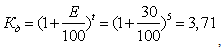 when: Е- the rate of return is taken equal 30%;t- the number of years of innovation set to 5 years.
Table 1. Initial data for calculation
 |
| |
|
This result shows that after five years, every ruble invested in the modernization of the locomotive 2TE10L to increase to 3,71 rubles.It is known that the discount rate should also take into account the factors of inflation and the risk (if they are already included in the discount rate). Therefore, the discount rate, adjusted for inflation, but without the risk, defined as: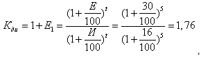 when:
when:  - ante inflation is assumed to be for the current year 16%;
 - discount rate to inflation.Therefore,
 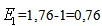 It can be seen that the magnitude of the risk discount rate is less than the discount rate without taking it into account. This is due to the fact that inflation erodes the money supply. With due regard for the risk index will calculate the discount rate based on:
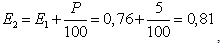 when: P - correction factor that establishes the degree of risk.Since upgraded to use an existing locomotive, then choose the lowest bid in the amount of risk 5% . Indicator of the payback period of capital investment is the payback period, which is defined by the dependence:
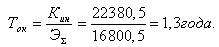 when:
when:  - total investment in innovation;
 - the net result (cash flow).Based on the foregoing, it is clear that for 1,3, this project will cover all costs associated with the implementation of the proposed design for lubrication of castor crests 2TE10L locomotive of wheelpairs.To automate the calculations to establish the cost-effectiveness of the use of the proposed technical solutions, developed a method of performing calculations on a computer using the language of Delphi. The analysis of numerous research and literature, as well as domestic and foreign patents allowed us to develop yet another technical award recognized the invention (SU1020259), aimed at reducing the forces of friction occurring in the contact area of the castor crest wheelpairs with the tramway without the use of a liquid, plastic or solid antifriction.
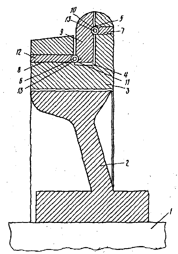 | Figure 8. Perspective cross rail wheels movable crest |
 | Figure 9. Design scheme of force loading the crest |
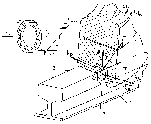
This solution, Figure 8 is a wheelset on the axis which pressed onto one wheel center with a bandage 2 3. The latter has an annular groove 4, and its vertical surfaces are made concentric hemispherical recesses 5 and 6 coincide with the respective cylindrical holes 7 and 8 located in the shroud 3. In the recess 4 are arranged two half ring 9 is also provided with concentric hemispherical recesses 10 and 11. Bores 7 and 8 inserted into the cap 12 and between the recesses 5 and 10 and 6 and 11 are movable rolling bodies 13.Going wheelpair follows. In the annular groove 4 and at its bottom end portion of the layer of grease. Then, in the groove 9 introduces two semicircles, and their geometrical sizes support the walls of the groove a snug fit. Then, in the opening 7 and 8 entered the rolling 13 lockable caps relative to the shroud 12. Thus, semicircles 9 are able to rotate relative to the shroud 3, while being secured against radial movement relative to the shroud.When the locomotive or wagon wheepairs of provided with such a small radius curves in the frictional forces between the wheel flange and tramway head, crank half ring 9 and thereby reduced wear.The geometrical characteristics of components for such a device will produce, for example, in relation to career diesel locomotive TEM 7, which axle load[1-4] is  wherein a lateral force
  when entering a curve in the path of the locomotive and the recommendations[3] is assumed to be
  burden attributable to each castor wheelpairs. Therefore,
  For the calculations used design scheme Figure 9, which is the castor of the locomotive TEM 7, and rolling along the tramway under the influence of torque at an angular velocity
 . At a point on the castors in contact with the tramway of its own weight of the locomotive there is a normal reaction N, the friction force Fтр and a lateral force
  . Angle
  formed by the normal N and the overall reaction is the angle of friction F. Under the influence of lateral force
  several rolling elements by forming a half-rings 9 (see Figure 9) any reaction RН and RВ, which will be attached to the carbon α characterizing the contact area of the castor crest to rail. In which area may be several rolling elements along the generatrix of which half shells depending on the selected diameter. In the contact zone running circle wheel-rail the contact area, which is close to the shape of the ellipse area
  [3]. Then the contact area, arriving at castor crest to average
  . Determine the specific load in the contact zone
 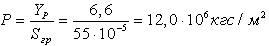 . We believe that the speed of the locomotive during the passage of the curve path is
 , and then speed wheelpairs, respectively, will be:
  when
when  - diameter of the castor wheelpairs equal 900мм;The angular velocity of the castor is determined depending on the:
 Assume in the first approximation, that the rolling bodies in the zone of contact polugrebnya 1 formed integrally with the the castor shroud 2 (Fig.9) and the shroud-side two the castor constituting its driving range, are symmetrical to each other relative adjustment section 3 D-rings, loaded with reactions Rmax, arising from the action of force Rр, vector directed in the opposite direction with respect to a lateral force
  , equal
  It is known[4] that the height of the castor crest locomotive TEM-7 is 33 мм, and the width in the largest cross-section as 33 мм. We assume that in this section can accommodate components of the the crest 1 and 3 (Fig. 9) with the corresponding rolling elements. On this basis, assign them to the width of the 16,4 мм then the diameter of the rollers may be chosen as 12 мм. On the basis of the length of the arc of contact of rolling elements with the head tramway, it can accommodate up to 3 order of rolling elements, and perceive that the lateral force in
 Given that load
  acts uniformly on all the rolling elements, and only a portion of them and contributes to sag half-rings, then the three body rolling action of the load is determined by the formula[4]:
 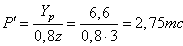 We define the maximum value of the contact voltage σmax, using the basic provisions of methods[3], assuming that the force exerted on one body rolling is Р1 = Р′/3 = 2,75/3 = 0,917 кН, elasticity modulus Е = 2,2·105 МПа, the diameter of the rolling element d = 1,2 см, the radius of the surface under the rolling body is made on the half-rings r = 0,95 см, diameter of the half-rings stacked on the rolling surface of the rollers D = 93,0 см and Poisson ratio μ = 0,3.To solve this problem we denote the index A rolling body and the half-rings in the form and then can write the following principal radii of curvature and the curvature of the main body A and B as follows:A body (body rolling) ρ1 = ρ′1 = d/2 = 0,6 см, К1 = К′1 = 1/ ρ1 = 1,6 1/см;In the body (forming a half-rings) ρ2 = – r = – 0,95см, ρ′2 = –D/2 = – 46, 5см, К2 = 1/ρ2 = – 1,05 1/см, К′2 = 1/ρ′2 = – 0,022 1/см.The minus sign in front of the parameters ρ2 and ρ′2 raised, because the contact surfaces are concave half-rings forming. Now we perform the following calculation parameters m, n, and cosθ formulas[21]:
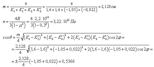 Corresponds to the value of the cosine of the angle
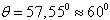 .Using data tables presented in reference[21] found numerical values α = 1,486 and β = 0,717 and then, according to the corresponding formulas determined by the following parameters:
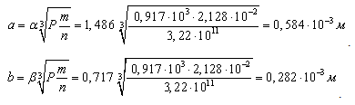 The numerical values of these parameters allow you to define σmax, then:
 .Consequently, the condition of the contact resistance holds.The calculations performed, with respect to the wheel pair of industrial diesel locomotive TEM 7, justify geometric dimensions of the proposed technical solutions, and in particular to determine the material steel device SH15 and rational equal to the diameter of the rolling element 12 мм, and ensure that the specified performance and the strength of the element base of the proposed technical solutions.
4. Conclusions
Results of the study are recommended industries that exploit and manufactures railway rolling stock, both in our country and abroad to study the proposed technical solutions and possible further put them into practice. This is confirmed by the fact that, firstly, the proposed technical solutions created at the level of a number of inventions (RU2236364, RU2236362, RU2236363, RU2236361, RU2238207, RU2238206, etc.) and have no analogues in the world.Second, the example of the patent RU2344956 developed analytical model and the numerical solutions for geometrical properties of the design and operating characteristics of the device using a solid lubricant with the following physical and mechanical properties of the crystal lattice parameters, 10-6 mm - a=1,42; c=3,25;  ; density of 2,1 ∙ 103kg/m3; modulus 5050 MPa; oxidation temperature 6730 K, and the decomposition temperature of 37730K. Thus, for example, freight cars operated on the site Elec-Leo Tolstoy UVJD set flow rate of solid lubricant, which will suffice for a period of t = 0,82 years.Third, the proposed design of the device (RU2373090) intended for the lubrication of wheel flanges locomotive that uses a liquid lubricant. Selecting lubricant for such devices made with reference to diesel locomotive TEP60 while recommended industrial oil I-N-E 220 to GOST 17479,4-87 kinematic viscosity υ50 = 242 sst at 50℃ in the friction zone. Calked that its flow path to the curve of about 1000 m on average would be about 1,2 kg.The fourth is considered a promising solution (SU1020259) does not require lubrication of wheel flanges by replacing sliding friction occurs in the contact zone of ridges with a head rail on the rolling friction. As a result, industrial diesel locomotive TEM-7, calculated the geometric dimensions of the proposed technical solutions, and in particular certain material steel device ШХ15 and rational diameter of the rollers of 12 mm.For the calculation of the element base of the proposed technique reduces of castor crests wear of wheelpairs, and the type of lubricant, when used in a variety of designs of locomotives and wagons developed a computer program using the language of Delphi, which was tested in the examples shown above. It should also be noted that the calculated parameters determined by this method are approximate and can not be recommended for momentary use and therefore for the final evaluation of the effectiveness of the use of the proposed technical solutions necessary to carry out extensive tests on their efficiency and effectiveness, as in the bench and operational conditions.
References
| [1] | The design analysis and design of locomotives. A textbook for university students. А.А. Kamaev and etc. By ed. А.А. Kamaeva М.: Engineering, 1981 y. |
| [2] | The design and dynamics of locomotives. By ed. V.N. Ivanova, 2е ed. ad. М.: Transport, 1974 |
| [3] | Wagons. By ed. L.А. Shadura, 2е ed. М.: Тransport, 1978 y. |
| [4] | The dynamics of the car. S.V. Vershinskyi, V.N. Danilov and I.I. Chelnokov. М.: Transport, 1972 y. |
| [5] | Danilov V.N. Rail Road and its interaction with the rolling stock. М.: Transport, 1961 y. |
| [6] | Locomotives. Design theory and calculation. By ed. N. I. Panova. М.: engineering, 1973 y. |
| [7] | Ershakov О.P. Calculation of the horizontal forces in curves. М.: Transport, 1966 y. |
| [8] | Andrievskiy S.М.. Side rail wear in curves. Proceedings of the Central Research Institute, is. 207, 1961 y. |
| [9] | Bromberg Е.М. and etc. Interaction of track and rolling stock. М.: Transzheldorizdat, 1956 y. |
| [10] | Conclusions tramway and the castor. V. Baryshev. Newspaper Horn of 18.03.89 y. |
| [11] | Steel SPID Newspaper Horn of 6.10.90 y. |
| [12] | Kirichenko А.I. Craneways. М.: Engineering, 1966 y. |
| [13] | SU 1206156АМКИ В61 К 3/00. Wheelset rolling stock. |
| [14] | SU 1652153АМКИ В61 К 3/00. Device for lubrication of the rails on the curved track sections. |
| [15] | SU 1652154 А1, МКИ В61 К 3/02. The device for of the castor crest antifriction of rolling stock in the curved sections of track. |
| [16] | SU 1759704 А1, МКИ В61 К 3/02. Device for lubricating of castor crests wheelpairs rail vehicle. |
| [17] | SU 1801838 А1, МКИ В61 К 3/02. Device for antifriction of the rails. |
| [18] | SU 1801839 А1, МКИ В61 К 3/02. A device for lubricating rails. |
| [19] | SU 1801840 А1, МКИ В61 К 3/02. A device for lubricating rails. |
| [20] | SU 1824336 А1, МКИ В61 К 3/02. Device for antifriction of the rails. |
| [21] | Garkunov D.N. Tribotechnika. A textbook for university students, 2е ed., revised and supplemented — М.: Engineering, 1989 y. |
| [22] | Lubricants. Anti-friction and anti-wear properties. Test methods. Handbook. R.М. Матвеевский and etc. — М.: Engineering, 1989 y. |
| [23] | Slivinskiy E.V., Chumichev V.N., Lark Parakhina N.N. Bykov and OS "A calculation using the program on a computer key characteristics of devices for of castor crests antifriction of locomotives." Computer science: concepts, current status and prospects for development. Proceedings of the scientific-methodological seminar. YSU name. Ivan Bunin, elec, 2005. |
| [24] | Slivinskiy E.V., Mitrofanov S.Y. Development of promising structures for of castor crests antifriction of rolling stock. Actual Problems of Engineering[Text] Sat Nauchn. – Lipetsk, Lipetsk State Technical University, 2009. - 286s. |
| [25] | Gilyarovskaya L.T., Endovitsky D.A., Financial and investment analysis and audit of commercial organizations. – Voronezh, Voronezh State University Publishing House, 1997. - 336. |
 Abstract
 Reference
 Full-Text PDF
 Full-text HTML