E. V. Slivinsky1, V. I. Kiselev2, S. Y. Radin1
1Mechanical Technological Faculty, Elets State University I.A. Bunin, Elets, 399770, Russia
2Mechanical Faculty, Moscow State University of Railway Engineering (MIIT), Moscow, 127994, Russia
Correspondence to: E. V. Slivinsky, Mechanical Technological Faculty, Elets State University I.A. Bunin, Elets, 399770, Russia.
| Email: |  |
Copyright © 2012 Scientific & Academic Publishing. All Rights Reserved.
Abstract
This article deals with the development of advanced designs wheel-motor blocks (WMB) locomotives. These structures differ significantly from prior art in that they contain motor-axial bearing (MAB). Therefore, they increase the operational reliability of locomotives. Techniques of identifying the basic kinematic and geometric characteristics of a number of examples of the developed technical solutions. The results of studies recommended design, research and machine-building enterprises developed units for possible use in practice.
Keywords:
Motor-axial Bearing, Traction Motor, Wheel Pair, the State of Stress, Axle Hubs, Gear, Console
Cite this paper: E. V. Slivinsky, V. I. Kiselev, S. Y. Radin, Increase of Reliability of Wheel-Motor Blocks of Locomotives, International Journal of Traffic and Transportation Engineering, Vol. 2 No. 5, 2013, pp. 91-100. doi: 10.5923/j.ijtte.20130205.01.
1. Introduction
The modern, both domestic and foreign diesel locomotives, electric locomotives and electric trains preferential distribution received individual drive on each wheel pair. Individual drive requires a minimum difference in speed characteristics of traction motors installed on a locomotive. This is the main disadvantage of the latter. The second type of the drive belongs to the group, which transmits torque from one traction-motor simultaneously on two or three wheel pairs. This drive circuit greatly simplifies the wiring scheme of the engine, increasing the use of coupling weight, but because of the complexity of the design, wide dissemination of the main Railways has not received [1-5].It is known that most of the freight locomotives with electricity transmission, which have a design speed of 120 km/h and more, are equipped with individual drives the driving wheels with the supporting-axial suspension of traction motors. On diesel locomotives such transfers do usually unilateral. Gear in such a suspension of traction electric motor (TEM) is working in difficult conditions caused by the variable work regimes and dynamic loads. A deterioration of the conditions of work contributes to the deformation of the wheel pair and shaft anchor TEM, as his gear is located knee. At the same time, the teeth of the gear pair is constantly broken for the depreciation of the motor axle bearings (MAB) the value of which in the operating conditions reaches 3 mm and more. Therefore, in practice, for recovery of the wheel-motor blocks of locomotives are widely used expensive repair works, carried out in depots and diesel locomotive works. In designs of diesel and electric locomotives commonly used scheme supporting-axial suspension TEM. These powertrains are called, both unilateral and bilateral, the latter can more efficiently distribute the load, perceived TEM shaft and motor-axial bearings. However, in this case the use of MAB is not efficient enough and thus failures in their operation significantly affects the reliability of the locomotive fleet.
2. The Aim of the Research
Analyzing the above shows that the supporting-axial suspension TEM has a number of significant deficiencies, which significantly reduce the reliability of freight diesel locomotives in operating conditions. Consequently, at the present time there is a need to upgrade WMB due to the exclusion of its construction, motor-axial bearings.Given this, in ElSU I.A. Bunin, at the Department of applied mechanics together with the Department of locomotives and locomotive economy MIIT for a number of years conducted research on the topic «Dynamics, strength and reliability of transport, road construction and agricultural machines, as well as the industrial standard and non-standard equipment in relation to Black-earth region of the Russian Federation» and one of its sections is the scientific direction is connected with the development of promising designs of wheel-motor blocks with increased technical and operational reliability.Analysis of numerous bibliographic sources, as well as domestic and foreign patents allowed to develop at the level of inventions (RU2242389, RU2251504, RU2284930, RU2255014, RU2432278, RU2399529, RU2399528) promising design WMB completely eliminating the use of MAB.Therefore, the aim of the research is the study of the efficiency of the proposed structures WMB and determination of their basic geometrical design features to provide a framework for their design and in the future possible use in practice.
3. Methods
Let us consider the proposed technical solutions created at the level of inventions. So in figure 1 and figure 2 shown, for example, one of these constructions (RU2242389) consisting of axis 1, on which the wheel centers 2 are pressed. Cervix 3 of axis 1 housed in the journal boxes 4, which are integrally formed with the arms 5, and they are through holes 6. The ends of the arm portions 5 are provided with taper 7, placed precisely in response holes 8 formed on skeleton traction motor 9. The skeleton of traction motor 9 with torsion bar suspension 10 is connected to the frame jaw-carts 11. On the shaft 12 of the traction motor 9 is fixed pinion 13 interconnected with gear 14, rigidly mounted on the axis 1 of wheel pair.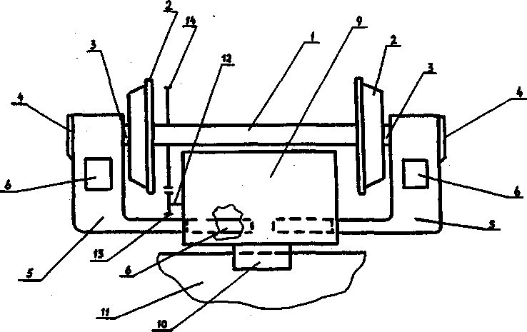 | Figure 1. Wheeled motor block top view |
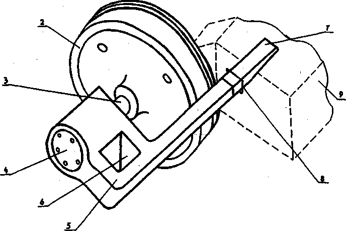 | Figure 2. Part wheeled motor block in the long term |
The work of the wheel-motor block is as follows. For movement of the locomotive wheel-motor unit is mounted on the jaw carriage frame 11 so that it guides (in figure not shown) included in the vias 6 of arm 5. Previously, each of the levers 5 from the lower part 4 is pressed onto the neck 1 of wheelset axles, the ends of arms 5, provided with tapered portions, the holes 8 are formed in the backbone of the traction motor 9 and the end of this operation, occupy a position such as that shown in figures . Since the tapered portions of levers 5 and interfaced them holes 8 are precision pair, the shaft 12 of traction motor 9 is strictly parallel position relative to the longitudinal axis of symmetry axis 1 of wheel pair, and it lies in the same plane. Consequently, the pinion 13 and gear 14 have a precise and unchanging in service center distance. After that, tighten the nut located on the frontal axis 1 of wheelset, fix them and torsion bar suspension 10 is placed on the frame of traction motor 9. During the movement of the locomotive with the proposed suspension of TEM and possible vertical movement of axle box 4 relative the jaws of cart, is moved in the same plane and the arms 5 and, therefore, the skeleton itself traction motor 9, but such movement may not affect misalignment of the shaft 13 with respect to the longitudinal the axis of symmetry axis 1 of wheelset, and it provides a stable center distance between them and provide a fairly long lifetime of the locomotive, as the durable axle box bearings is high enough[10].At the same time, another traction drive of locomotive with motor axial suspending a promising design (RU2251504) which also lacks motor-axial bearing and consists of a drive motor 1 is provided with tide 2, in contact compression spring 3 through a bogie frame 4. On the shaft 5 of the electric motor (figure 3) is fixed pinion 6 and its end portion is located in the self-aligning bearings 7, placed in a beam 8, that is provided with a vertical through hole 9 of rectangular cross section, as the location of the bracket pedestal bogie frame 4 and a horizontal circular opening 11 in which bearings 12 are molded neck 13 of wheelset axis 14. On the shaft 14 of wheelset is rigidly fixed driven gear 15 and the wheel centers 16.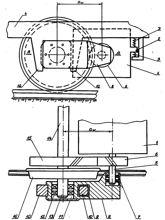 | Figure 3. Fixing wheeled motor block to the journal box |
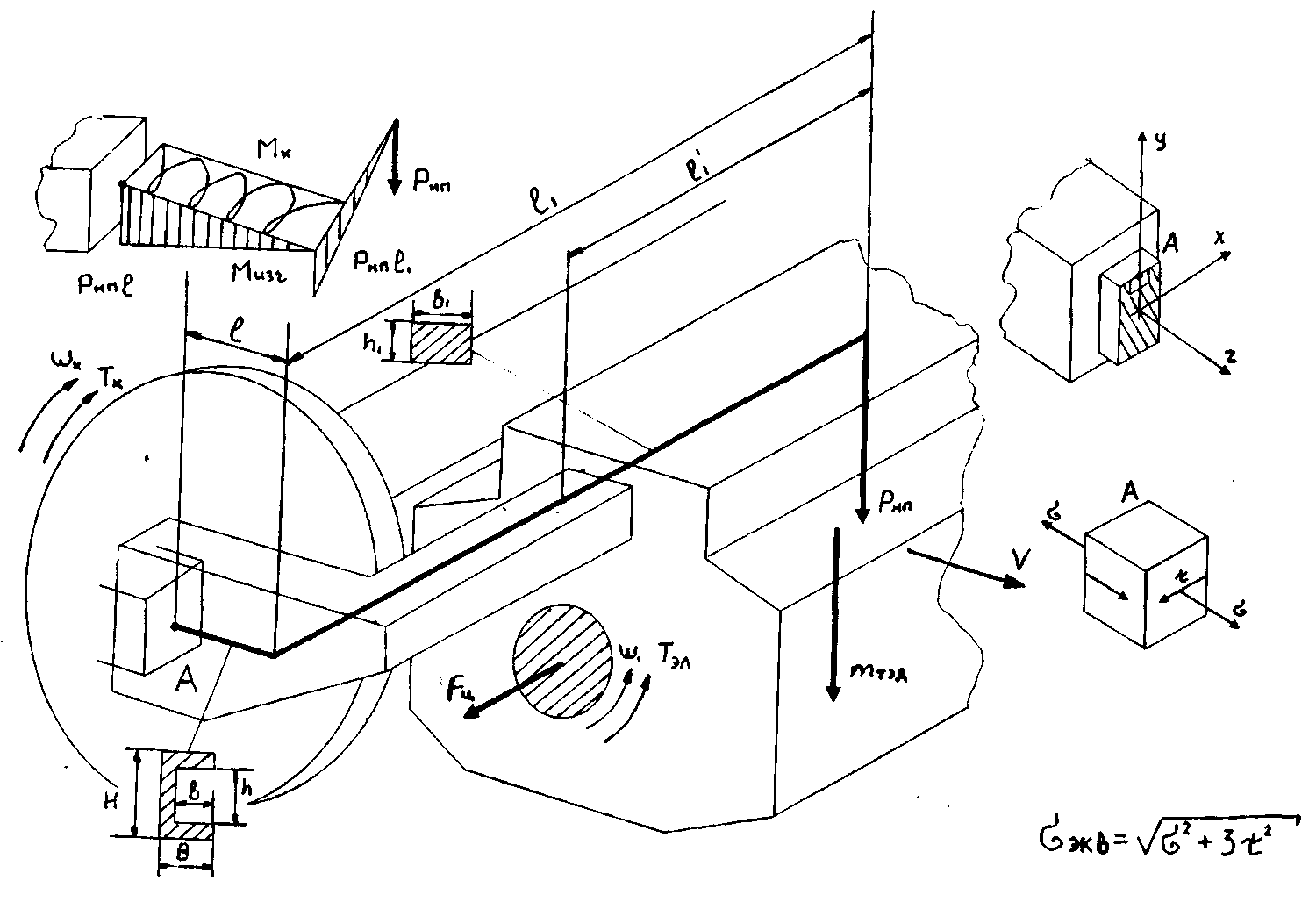 | Figure 4. Design scheme |
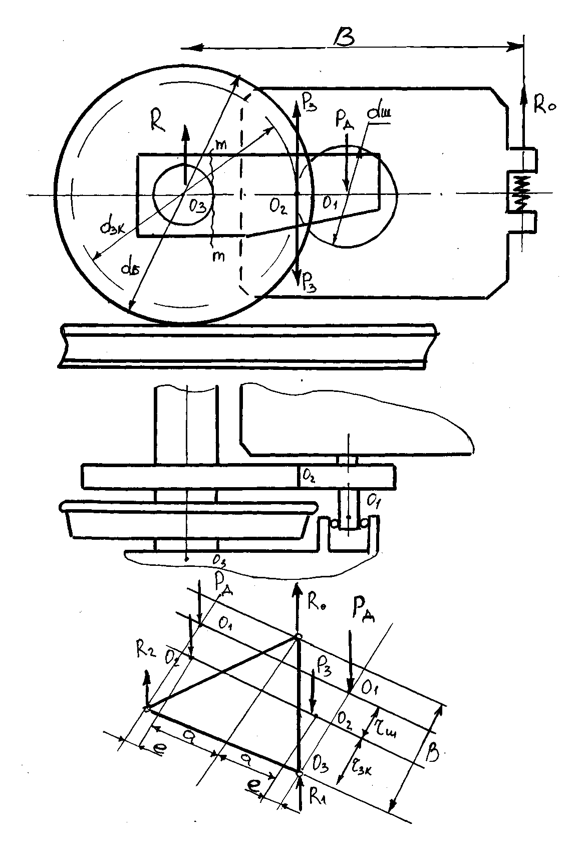
Works locomotive traction drive as follows. When power is applied to drive motor 1, a rotating shaft 5 is at a predetermined angular speed and the torque transmitted through the gears 6 and 15 on the wheelset axle 14 that contributes to its rotation and hence movement of the locomotive. When all modes of operation of such a movement gear is in favorable (in terms of wear of the teeth) conditions due to the fact that the center distance аw is constant and does not change, as is the case in the famous serial constructions drive motor and axial suspending the traction motor, as the shaft 5 of its anchors and neck axis 13 of wheelset with rolling bearings are in the same rigid beam 8, centered arm 10 of axle box jaws of frame cart. Based on the fact that the life of box bearings of locomotives now exceeds 4·10 km of their run the constancy center distance аw is always well defined, and therefore the reliability of the gear provided.To determine the geometrical characteristics of the bearing structure of TEM, which is the leverage taper plots (fig. 1 and fig. 2) we use the calculation scheme shown in figure 4. The design scheme includes a "Г" - shaped lever, one end of which is connected to the wheel pair axle boxes, and the other with the core of TEM. The most dangerous in terms of structural strength, a point A in the root section of the lever "Г" - shaped. Loaded lever inertial force  occurring in the motion of the locomotive, and has a length of the constituent rods and shoulders l and l1, and in each of the arms of the cross section is the correct size h, b, H and B. From the inertial force
  shaped rod any normal σ and σ1 and shear stress τ, while the bending moment diagram
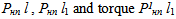 will have the form shown in figure 4. Anchor TEM locomotive, rotating with angular velocity ω1, transmits torque Тэл to the wheel, the angular velocity is ω2<ω1, provides a torque to the wheel pair Тк. Some numerical results to determine the stresses in the cross-sections of land "Г" - shaped rod, for example, for WMB locomotive
  It is known[1-3] that the dynamic component of Рнп passing wheelset interface with the speed of the locomotive V = 100 km/h is 12.89 t, hence, on one end of the "Г" - shaped rod (their 2-way, forming weighed TEM) is a force to be equal to Рнп/2 = 6.45 t. The material used in the manufacture of steel levers choose 40 GOST 1050-74 with σт = 321 MPa and σв = 586 MPa, НВ183 and ан=59 J/сm2. Based on the geometric dimensions TEM of the locomotive
  set the length of the rod sections "Г" - shaped, respectively, l = 504 mm, l1= 1110 mm. Just take constructive measures cross sections of the lever (fig. 4) b = 160 mm, b1 = 200 mm, h = 310 mm, h1 = 70 mm, B = 200 mm, H = 350 mm. Given that upgrading WMB can significantly affect the safety of the rolling stock, establish a safety factor n = 3. Numerical values of the normal stresses σ, σ1 and τ by the formulas[6,8,12].
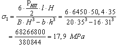
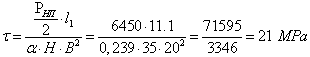
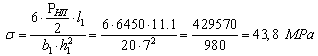 | (1) |
 | (2) |
 | (3) |
where: α - coefficient depending on the ratio of the long arm of the profile l and equal 0,239 (350/200 = 1,75) is determined from the table[6]. From the above calculations show that the highest value of σ and σ1 is the normal stress σ = 43,8 MPa, and therefore, using this value to determine the equivalent voltage dependence: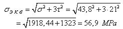 | (4) |
We believe that the allowable stress[σэкв] will determine the yield stress σТ, which for steel 40 is σТ = 321 MPa,  In our case σэкв = 56.9 MPa <[σ] = 107 MPa. As a result, we can say that the strength condition is satisfied and the proposed device sample TEM in service will be reliable enough. To ensure immobility TEM on sites l, "Г" - shaped rods, nominal pressure qm on mating surface of the latter with the holes made in the skeleton of the TEM must be such that the frictional forces exceed external force Fц, which occurs when entering a curve path and reaches its maximum value. Define the centrifugal force acting on the TEM Fц own weight which
  the speed of the locomotive V = 120 km/h (33,3 m/s) and the radius of the curve path η = 300 m using the formula[3]:
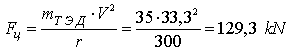 | (5) |
Define the landing "Г" - shaped rods made of steel 40 GOST 1050-74 in the hole core TEM has similar material. We believe that the landing surface roughness corresponds to Rа = 2,5 microns and a compound is collected on the press, using transformer oil. The coefficient of friction in the contact mating parts f = 0,1. We define the contact pressure in the compound of the formula[8]: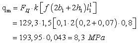 | (6) |
where: k - factor of the shift will take a 1,5[6,8];l11 - the length of the landing of the "Г" - shaped rod; l11 = 800 (set constructively);b1 and h1 - the geometric characteristics of the rod "Г" - shaped respectively equal to 200 mm and 70 mm.For the selected steel 40 of the tables[8]: install the module of elasticity Е1 = Е2 = 2,1∙105 MPa and Poisson's ratio μ = 0,3 and then determine the minimum preload as follows: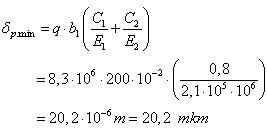 | (7) |
where: С1 and С2 - coefficients chosen from the table and depending on the geometry of the cross section "Г" - shaped rod, and Poisson's ratio.We define the minimum required pre-tightness of the tables[44] by setting the value of Rz = 10 mkm. Then | (8) |
We find the most current tightness of the formula: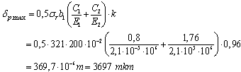 where: k - coefficient characterizing the site, which defines the voltage and equal to 0,96[8].Now we calculate the maximum desired preload the polishing of asperities
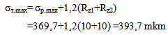 | (9) |
The tables[7] select landing so thatδmin≥ δт.min=44,2 mkm, δmax≥ δт.max=393,7 mkm. Under these conditions suitable landing - 200 Н7/Х8.Joining the effort to define the selected landing dependence: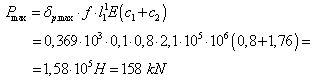
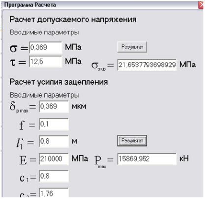 | Figure 5. The window of the computer program |
Hence, Рmax>Fц 1,22 times, the connection of each of the "Г" - shaped rods with a core stator is safe.Earlier in the calculation of the power load bearing elements of "Г" - shaped TEM suspension arms have been used prior to the size b1 and h1, however, to determine their optimal size to make payments σэкв and Рmax for different engines as the main, and industrial. Given this feature, a program in the language of Delphi, allowing to solve such problems[9]. The window of the program, as an example shown in Figure 5.To determine the forces acting on a rigid beam suspension TEM performed by Pat RU2251504 (Fig. 3) and test their strength in relation to the modernized WMB, for example, electric ВЛ80 in which each wheel pair axle is equipped with two gears developed analytical model (Figure 6) , and it shows the strength  respectively, attached to the frame of the trolley, the bearings rigid beams to the teeth of the transmission and wheel pair axle boxes through its nodes at the points О, О1, О2 and О3.It is known that prolonged thrust
  one section of the locomotive is 27000 kg consequently on its one wheel pair, this force will be equal to 4500 kg[1-3]. Then the peripheral force in the gear train from one of the wheel pair is determined from the dependence
 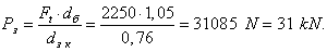 From the condition of equilibrium of forces acting on one of the beams can be hard to write the following relationship:
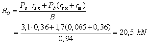
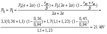
 | Figure 6. Design scheme |
Imagine a rigid beam as beam, located on two pillars at the site О1-О3 (Fig. 6) and define the internal power factor Мх, amounting momentum equation for the cross section m-m, for which the boundary conditions can be written as: 0≤X1≤0,449 m: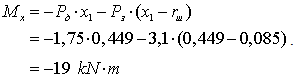 As a material for rigid beam accept Ст3 GOST 380-88 with[σ] = 160MPa and define its section modulus Wх as follows:
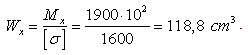 This value allows Wх as rigid beams arranged in a bogie frame jaw nodes and carrying on its other end bearing assemblies armature TEM, use sills GOST 8240-72 profile №22 in which Wх = 192 cm3. Taking into account the dynamic loading of WMB in an operational environment, the design and geometrical characteristics of axle boxes and rails as rigid boards can be recommended hollow beam height h = 320 mm, width b = 210 mm and a wall thickness δ = 10,0 mm.Consider another promising design WMB are new and patent-protected RU2284930.Such a wheel-motor unit locomotive Figure 7 consists of the traction motor, gear, which is interconnected with the gear rigidly fixed to the wheel pair axle boxes equipped. The Bucs are attached to vertical portions of the additional beams that doubles as a lid bux. More horizontal part of the beam is rigidly connected by bolts to brackets traction motor, wherein the latter is also fitted with a spring tide suspension placed on the frame of the locomotive truck. Works WMB follows. When voltage is applied to the TEM gear transmits torque to the gear, and since it is rigidly connected to the axis of the wheel pair, the latter rolls on rails, allowing movement of the locomotive in one direction or another. During the movement of the locomotive bogie exposed irregularities and the way it makes the vehicle-part complex spatial variations, including the vertical, as well as the TEM connected through the appropriate parts bogie frame then it would seem possible violation of the center distance
  gear-pinion-gear. However, it does not mean that the TEM rigidly fixed to additional frame, whereas the latter also its vertical portions rigidly connected to the axle boxes. As a result of the wheelset makes movement in the vertical plane of the bogie frame in conjunction with TEM and this connection is reliable design for fixed center distance
  gear pair. At the same time, due to the fact that between the TEM and the bogie frame is elastic tie, made in the form of a spring suspension, the swinging of WMB not cause loading of a rigid frame, creating favorable conditions for the work of the latter.
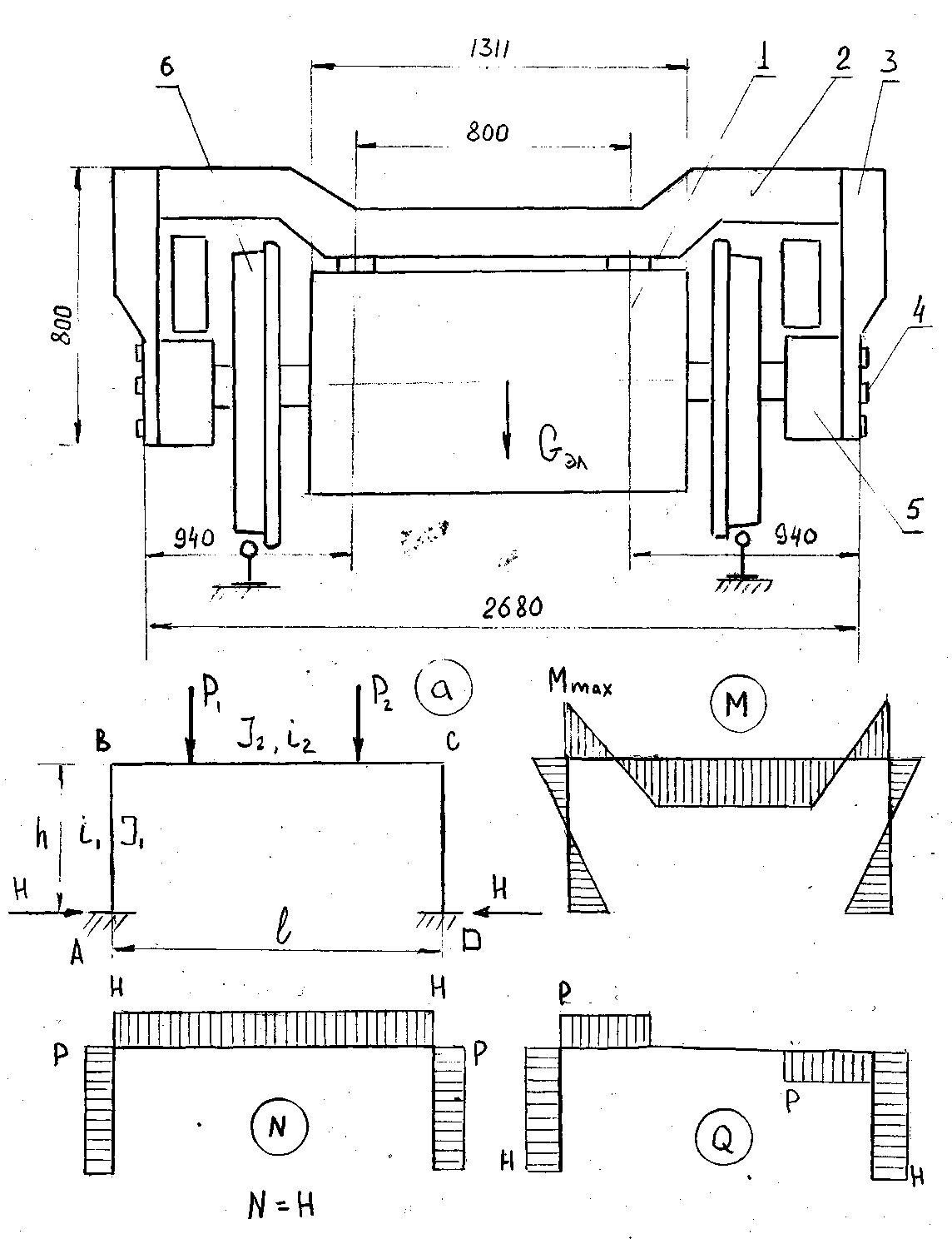 | Figure 7. General view of the WMB and loading diagrams |
To assess the strength of the proposed design WMB (patent RU2284930) in relation to diesel locomotive 2ТЭ10Л developed analytical model (Figure 7), from which a calculation on the strength of structural elements of the suspension TEM. On the design scheme of the traction motor 1 is firmly attached to the transoms 2, which is provided with a rack 3 also rigidly connected by bolts 4 with bux 5 of wheelset axle boxes 6. To simplify the calculations represent the bolt and strut in the form of П shaped frame (Fig. 7) with the following geometrical characteristics: the length of bolt l = 2,68 m, height h = 0,8 m, the moments of inertia of the cross-bar and racks of J2 and J1, stiffness per unit length bolts and persistent i2 and i1. By transoms at fixing TEM applied concentrated forces Р1 and Р2, which are equal and correspond to the condition 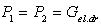 . The pattern of distribution diagrams M, N, and Q is shown in the same figure. To simplify the task of setting management section structural members of П-shaped frame, assume that the forces Р1 and Р2 can be represented as a resultant force Р and then the numerical values of the bending moments МА and МВ to define dependencies[6,8]:
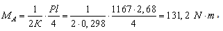
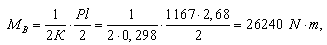 where K is the ratio of linear stiffness i2 and strut bolt i1 that is
  .Let us also assume that the moments of inertia of the posts and crossbar are the same
  and a large box section and then we can write:
 ,
,  , and then
 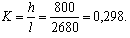 Now we define a numerical value depending on the thrust H[6,8]:
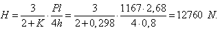 For the selection of the geometric characteristics of the cross sections crossbar and racks use dependence[8]:
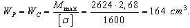 Given that during the movement of the locomotive said structural elements exposed dynamic loading, as well as the dynamic coefficient in this case may be adopted КД = 1,2[6.8] we will secant modulus crossbar struts and equal to:
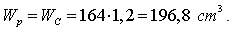 Product mix GOST 30245-94 choose as a closed section of welded square section size of 160×7 mm W = 205,1 cm3 and F = 42,8 cm2. Accept as allowable stress for the material from which made a specific profile
 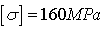 .Verify the strength of the bolt and racks as elements of compression with bending:Rigel - bending moment Mmax =2624 kg∙m and
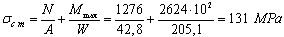 < 160 MPа,
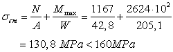
 <160 МPa.Condition strength bolts fulfilled.Support - bending moment Mmax =26240
  и
и
 ,
, <160 МPа.Strength condition is also satisfied.Since the front frame at their ends, by means of bolts installed in them without clearance is rigidly secured to the journal boxes wheelset then perform calculation of shear under the influence of shear forces H shown in orthographic Q according to[8]:
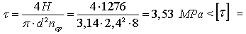 49,0 MPа,where d - diameter of bolt cm;n - number of slices, 8;
 .Принимая во внимание, что
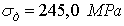 Taking into account that the material for bolts
  are made of Ст3, and that they are dynamic forces arising from different modes of movement of the locomotive characteristic operation conditions.Consequently, the strength condition is satisfied.Taking into account the structural characteristics of perspective WMB of, for example, for diesel
  and the fact that it can be used in practice, at the same time developed organizational and technical arrangements for the servicing of locomotives assigned to the locomotive depot Elec UVJD branch of JSC "Russian Railways".As noted above, a significant drawback wheel-motor units of locomotives, bogies fitted with jaw is skewed skeleton traction motor due to gaps emerging in the process of wear (MAB), which leads to a violation of the engagement TEM gear and gear located on the axis of the wheel pair. Increased wear of the motor-axle bearings often occurs due to a lack of effective lubricant supplied to the friction zone polster, who, especially at low temperatures, lose their conductivity, and therefore, as a consequence, a lot of time idling locomotives in depot repairs associated with the replacement motor -axle bearings and worn out that one reason the gear.
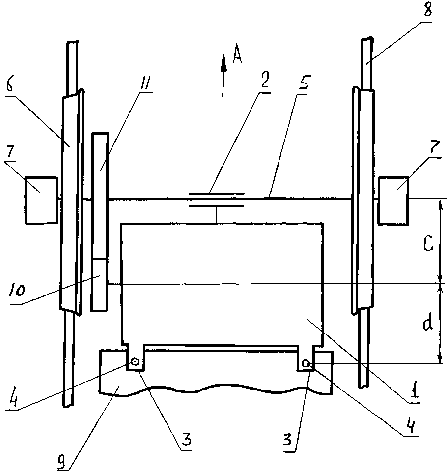 | Figure 8. Upgraded suspension of WMB |
With this in mind, consider another perspective design KMB recognized invention (RU2432278) and shown in figure 8.This figure shows a schematic diagram of wheeled motor block locomotive. In this case, the wheel-motor unit consists of an electric locomotive 1 on one side provided with a motor-axial bearings 2, on the other hand supporting the tides 3, with spring suspension 4. Motor-axial bearing 2 forms a rotational kinematic pair with the axis 5 of the wheel pair 6 axle boxes 7 fitted with rolling over the rail track 8. Spring hangers 4 in contact with the frame of the bogie 9 locomotive. Drive gear 10 of motor 1 forms a kinematic pair with the gear 11 rigidly fixed to the axis 5 of the wheel pair 6.Work wheeled motor block of locomotive is as follows. When voltage is applied to the motor 1, the torque via the drive gear 10 and the gear 11 surrenders to the axle 5 of wheelset 6 and the last translates along the rails 8, for example in the direction of arrow A. As in the static and moving at uniform vertical locomotive components of stress attributable to motor-axial bearing 2, and, therefore, on the axis 5 wheelset 6 and on the bogie frame 9 of hangers 4 can be considered equal. This arrangement differs from the standard MAB having one instead of two.It is known that, for example, in standard designs wheeled motor unit locomotive 2ТЭ10Л whose net weight of TEM is 3500 kg, the latter is hung on the axle wheelset with two MAB and a base connected to the trolley by means of the locomotive elastic coupling. In this case it is assumed that the axle wheelset with a twin-motor axle bearings on each one of them has to load Р3 from 1166 kg, and a support truck is the same 1,166 kg. Therefore, the axis of the existence of two poles will be attached to the static load 2333 kg.At the same time, for the same locomotive, which can be used in the proposed technical solution, on the wheelset axle load Р3 to act only 1166 kg as this design involves the use of only one MAB. We see that in this case, now the locomotive bogie frame will take a static load of 2333 kg, and the axis of the wheel pair is two times less than it is for the standard design of wheel-motor block of the same locomotive  To simplify the calculations to determine the state of stress, we assume that the axis is a single beam (fig. 9) of length l2, whose legs are wheels and wheel set for it in the serial version of the WMB accompanied by two external loads Р3 and Р2 are separated from the poles where there are support RA and RB of the reaction, respectively at a distance l2 – l3 + а, and for the proposed WMB to a load beam Р1 spaced apart from the support В in a distance b/2 + l5, and from the support А at a distance l2 – l3 + а +b/2. Given this action forces for mass WMB maximum bending moment МMAX occurring on the axis will be:МMAX = RB(l5 + b) – P1b = 1431(0,12 + 0, 54) - 1166·0,54 = 3149 N·m,as for the proposal, the same rate (М1MAX), will be equalМ1MAX=P1(b/2+l5)(l2–l3+а+b/2) / l2 = 1166(0,27+0,12) (1,58-1,325+0,095+0,27) / 1,58 = 1784,4 N·m,where, l2 = 1580 mm, l5 = 120 mm, b = 540 mm, l3 = 1325 mm, а = 95 mm.Analyzing the obtained numerical values of the bending moment is seen in the case of using the proposed structure WMB compared to standard it decreases 314,9/178,44 = 1,76. It is known that the dynamics of these factors will increase an average of 1,25 times, respectively, and their value may be equal to 314,9·1,25 = 3935 N·m or 178,44·1,25 = 2230,5 N·m. Now assume that the axis of diesel couples in the span l2 = 1580 mm has a constant cross-section diameter d = 215 mm (diameter have a two-axis surface in the contact area of a 270 mm length of the MAB locomotive
  and then the normal bending stresses in her accordingly for serial WMB and perspective will be:σ = МMAX /Wx = 393,5·102/0,2d3 = 198 N/сm2σ = М 1MAX /Wx = 223,05·102/0,2d3 = 112 N/сm2.Comparing the values shows that the stresses arising in the wheel pair of the proposed design also WMB lower than in standard designs.
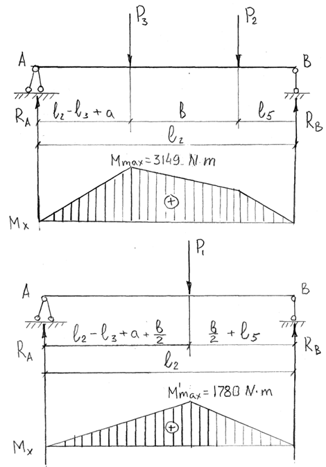 | Figure 9. Comparative diagrams of bending moments |
4. Results
Analyzing the foregoing, it is possible to draw the following conclusions. Since the analysis of currently existing structures WMB locomotives no longer meets modern requirements due to increased wear of the gear followed by a failure of the MAB due to poor lubrication in the area of the friction-bearing stub axle wheelset. Given this level of inventions developed technical solutions that improve the technical and operational reliability of the traction drives not only diesel locomotives and electric locomotives but also industrial vehicles. First, it is completely excluded from the structural WMB motor-axial bearings, using the axle box bearings wheel set or, secondly to reduce their number by transferring most of the loads from the traction motors on the bogie frame, not the wheelset axle.Analytical studies have confirmed that the proposed designs meet the strength requirements when choosing a rational geometric dimensions and provide predictable performance in the last operating conditions.
5. Discussion and Conclusions
The results of studies on these WMB transferred leadership of the Office UVJD branch of JSC "Russian Railways" as an interim report on the lines of research and recommends the appropriate scientific, engineering units and heavy engineering companies that produce locomotives motor-axial suspending TEM, both in our country and beyond abroad for further study of the proposed design WMB and its possible use in practice. To select the required material for the manufacture of hardware components of the proposed linkage parts and assemblies WMB, based on their strength and stability, as well as the development of the process, depending on the size and destination used software package for the computer, which was tested in the examples shown above. It should also be noted that the calculated parameters to be determined by known methods used are approximate and can not be recommended for momentary use and therefore for the final evaluation of the effectiveness of the use of the proposed technical solutions necessary to carry out extensive tests on their performance and reliability. Such tests are planned in conjunction with the industry and operational structures of JSC "Russian Railways" only if it will be open for research and development.
References
| [1] | Konstruktsiya and dynamics of locomotives. Ed. 2nd add. ed. Ivanov V.N. - Moscow: Transport, 1974 – 335p. |
| [2] | The design, analysis and design of locomotives. A textbook for students of technical colleges enrolled in "locomotive" / A.A. Kamaev and others, ed. A.A. Kamaev. - M.: Mechanical Engineering, 1981 - 350p. |
| [3] | Rail: The Encyclopedia / Ch. Ed. N.S. Konarev. Moscow: Great Russian Encyclopedia, 1994. - 559 p. |
| [4] | Technical directory of the railway. Volume 6. Rolling Stock. Ed. V.N. Sologubov. Gostranszheldorizdat. - M., 1952. - 955 p. |
| [5] | P.I. Orlov. Design Basics. Reference Manual. In the 2 books. Prince. 1 / under. Ed. P.N. Ugaev. Publication of 3rd rev. M., Engineering, 1988. – 345p. |
| [6] | D.N. Reshetov. Machine parts. A textbook for students of engineering schools - 4th revised edition. and add. M., Engineering 1989.-216p. |
| [7] | V.I. Feodosev. Strength of materials. Nauka, Moscow 1981.-312p. |
| [8] | S.D. Ponomarev. Springs. Machine parts. M. Mashgiz 1963.-153p. |
| [9] | Improving reliability of vehicle-diesel / A.I. Belyaev, B.B. Bunin, etc. Under. Ed. L.K. Dobrynin - M: Transport 1986.-96p. |
| [10] | I.M. Babakov. Theory of oscillations. - Moscow: Nauka, 1968.-345p. |
| [11] | Teplovozy. Design theory and calculation. / Ed. N.I. Panov - M: Mechanical Engineering, 1973. – 230p. |
| [12] | Shishkin K.A. and others. Teplovoz ТЭЗ. - M.: "Transport". 1970. – 296p. |
| [13] | Stepanov V.F. and dr. Teplovoz 2ТЭ10Л. - M.: "Transport", 1970, - 296 p. |
| [14] | Zhilin G.A. Passenger locomotive ТЭП60. - Moscow: Transport, 1971. - 376 p. |
| [15] | Kalihovich V.N. Locomotive traction drives (device, service, repair). - M.: "Transport", 1983. – 111p. |
| [16] | Kalihovich V.N. Traction gears electric locomotives. - Moscow: Transzheldorizdat, 1963. – 69p. |
| [17] | Kalihovich V.N. Improving the reliability of the engine-electric axle bearings. - The electric and diesel traction, number 8, 1980, p. 38-39p. |
| [18] | Avramenko V.S. etc. Effect of wear on the dynamics of transmission of the traction wheel and the engine block. Tr. VINITI, 1980, vol. 52, p. 63-68. |
| [19] | Biryukov I.V. The modernization drive components and their comparative testing. - Tr. Engineering, 1960, vol. 121. - Moscow: Transzheldorizdat, p. 98-121. |
| [20] | Dobrynin L.K. etc. The dynamics of electric linear actuators and motor УС4 electric train series ЭР. - Tr. VINITI, 1984, vol. 39, p. 173-178. |
| [21] | Chernavsky S.A. Plain bearings. M.: Mashgiz, 1983.-241p. |
| [22] | Gluschenko A.D., Jusko V.I. Dynamics traction motor locomotives. Tashkent. Publishers "FAN" UzSSR, 1980. – 168p. |
 Abstract
 Reference
 Full-Text PDF
 Full-text HTML