E. V. Slivinsky1, T. E. Mitina2, S. Y. Radin3, A. V. Karpachev2
1Mechanical Technological Faculty, doctor of technical science, Elets state University I.A. Bunin, Elets, 399770, Russia
2Elets state University I.A. Bunin
3Candidate of technical science, Elets state University I. A. Bunin
Correspondence to: E. V. Slivinsky, Mechanical Technological Faculty, doctor of technical science, Elets state University I.A. Bunin, Elets, 399770, Russia.
| Email: |  |
Copyright © 2012 Scientific & Academic Publishing. All Rights Reserved.
Abstract
This article presents information on the development of prospective construction of gear-type hydraulic machines which are widely used in various designs of transport, agricultural, road construction machinery, as well as various industrial standard and optional equipment, giving better productivity and reducing pulsation of working fluid and steel intensity. For this is provided the construction of gear teeth which are hollow and made of thin-walled metal tape by stamping. Calculated basic geometric and kinematic parameters of this construction, and a strength assessment of the hollow gear teeth is given. This engineering design is recommended for research and industrial structures in the field of engineering for further investigation and possible implementation.
Keywords:
Carcass, Gear Wheel, Thin-Walled Metal Tape, Slot, Control Rod, Suction Connection, Coverage, Rigidity
Cite this paper: E. V. Slivinsky, T. E. Mitina, S. Y. Radin, A. V. Karpachev, Modernization of Gear-Type Hydraulic Machines Which Are Used in the Construction of Various Types of Machinery and Equipment, International Journal of Traffic and Transportation Engineering, Vol. 2 No. 4, 2013, pp. 80-89. doi: 10.5923/j.ijtte.20130204.03.
1. Introduction
One of the main conditions of the increasing of the productivity of transport, agriculture, road construction machinery and industrial equipment is the improving of techno-economic figures of an actuator and the increasing of reliability. Usually an actuator consists of a propulsion system, a connecting gear, a control mechanism and auxiliary devices. Mechanical, hydraulic, electrical and pneumatic transmissions are used as a connecting gear. Each of these transmissions have their advantages and disadvantages, and are used in a particular machine or equipment, depending on the conditions of their usage, functions, range of application, etc. A hydraulic actuation mechanism got the most wide application after the creation of the domestic hydraulic equipment which can work at the pressure of  and higher in the open air, in dusty and dirty conditions, and at high (up to
  ) and low (down to
 ) temperatures [1-10,11-13].One of the main components of a hydraulic actuation mechanism is a volumetric pump, in which the movement of the working fluid from the suction connection to the decreasing space is carried out by the means of displacement of the working fluid from its working chambers by a displacer. A piston is the displacer in piston pumps, a tooth of a gear is the displacer in gear-type pumps, a vane is the displacer in rotary vane-type pumps, the surface of the screw is the displacer in screw pumps.
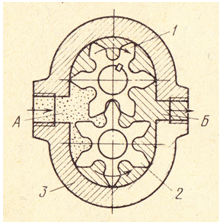 | Figure 1. A general view of the gear-type hydraulic machine |
Gear-type hydraulic machines which are plain in their construction, in comparison with the others, got the most wide usage in practice and are widely used in the design of agricultural machinery, automobiles, road construction machinery, etc. Such hydraulic machines (Figure 1) , for example, consist of a carcass(3), where the gears(1,2) are installed. Working fluid which is situated in the space between the gear teeth, transfers from the suction connection (A) to the forcing cavity(Б) by the means of the driving gear(1) rotation. In general gear-type hydraulic machines are used for the generation of pressure up to  , sometimes up to
  . But the weight, a high pulsation rate of the working fluid and low capacity are the essential defaults of such hydraulic machines.The following methodology is usually applied for the calculation of the characteristics of gear-type hydraulic machines [1-5]:The pump capacity is determined beforehand according to the dependence
  | (1) |
where  (area of the displacer, h- height of the tooth, b its width on condition that the tooth area is equal of the cavity area);
 - circumferential speed of the gears, where
  is the diameter of the pitch circle, and
  - their angular velocity.Taking the tooth height as
  (m – gearing module) and considering the addendum modification, the following formula is used for the determination of the pump capacity
 | (2) |
Appears from the above that the pump capacity is proportional to the quantity of teeth and the square of the module. That’s why pump gears with a small quantity of teeth and with a big module are used. It allows to diminish the size of the pump, but to increase the pulsation rate of the working fluid. Then determine the pump displacement formula | (3) |
The final stage of the calculation is the determination of the pressure forces on the bearings, which are basically bearings, depending on | (4) |
At present, the global engineering practices aimed at improving the design of hydraulic gear, and the demand for new technical solutions in the global community today is very important [21-25].With this in mind, the following describes the new unknown world practice gear hydraulic structures created at the level of the inventions of Russian Federation so as to avoid the above disadvantages of the prior art designs which, in turn, can improve their performance and effective use of the latest in hydraulic machines and drives.
2. The Purpose of the Research
Analyzing the above it can be concluded that the design of modern hydraulic gear commonly used in hydraulic cutting equipment, transport vehicles and agricultural and road-building machinery for today do not meet modern requirements, so they have a poor performance by a significant amount of working fluid pulsation enough metal and etc.Given this, the EHU them. IA Bunin, at the Department of Applied Mechanics for several years conducted research on "Dynamics, durability and reliability of transport, road construction and agricultural machinery, as well as the industry standard and optional equipment in relation to the Black Earth region of Russia" and one of its sections is the scientific field associated with the development of promising structures gear hydraulic meet modern requirements in terms of performance, lower ripple and metal working fluid.Analysis of research reports in the art, literature, domestic and foreign patents allowed to develop more efficient design of gear hydraulic protected by several patents for inventions (RU2338926, RU2341686 RU2246637, RU2269031). Therefore, the aim is to study the performance of the proposed design of gear hydraulic and determine its basic characteristics allow us to give a basis for its final design in the future potential use in practice.
3. Survey Methodology
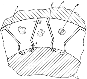
Consider the proposed solutions in detail. The first development made on the patent RU2338926 presented in the form of schemes where in Figure 2, shows a general view of gear hydraulic sectional in its vertical plane, in Figure 3 an enlarged view of the teeth of its gears and the cross-section in Figure 4 on the D - D of the hydraulic by suction cavity.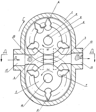 | Figure 2. Section of gear-type hydraulic machine |
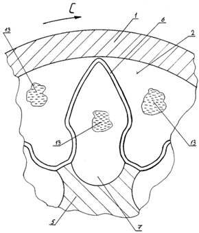 | Figure 3. Enlarged view of the tooth |
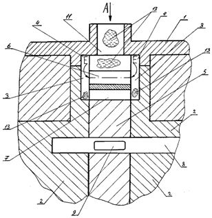 | Figure 4. Section of intake manifold |
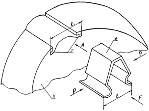
Gearwheel hydraulic machine consists of a casing 1, which are fixed to the wheels 2 grooves are made in three is a continuation of similar grooves 4 of the housing 1. Between fixed disks placed two movable wheels fitted with five teeth made from six pieces of thin plates. The wheels are equipped with five slots 7 and rigidly mounted on the shaft 8 with keys 9 and is free on axis 10. Case 1 has a suction port 11 and discharge pipe 12 intended for the current direction of the working fluid 13.Gearwheel hydraulic machine operates as follows. When applying torque to the shaft 8 of the last rotation of the wheels helps to 5, and by the fact that his teeth are six related engagement with counter, made from another wheel 5, they both turn at the same angular velocity of the arrows C. Such a rotation of the wheels 5 helps transport fluid 13 flowing through the suction port of the arrow a and deepening 4 and 3 in the hollow space of the teeth 6 and 7 slots, towards discharge 12 and then release it under the pressure of the arrow B. It should be noted that the proposed technical solution, the volume of fluid 13 is located in tooth space inside teeth 6 and 7 in the grooves is large and, slots 7 may not only have a semi-cylindrical shape, but also, for example, trapezoidal, rectangular, etc . etc. This would place them in an additional significant amount of transported fluid 13. It is known that uneven fluid supply 13 Gear hydraulic projections depends on the radius RG gear, the pitch circle radius r and pitch engagement t. At the same time, the average flow Q depends on these parameters, as well as the width of the teeth and the wheel speed. But as the number of transported liquid 13 is significantly increased, in general it will flow in the proposed hydraulic machines more uniform and stable. It should also be noted that the pulsation of fluid flow 13 is also available as a well-known machines, but its value is very small and is characterized by an area of only six teeth heads produced in the contact with the body 1 of the hydraulic machine.The second solution is aimed at improving the maintainability of the aforementioned hydraulic Gear and Figure 5 shows a general view of it in the context of the side, in Figure 6 an enlarged gear tooth profile and place it on the wheel and sealing in Fig.7 initially pair of gear tooth wheel hydraulic during its installation.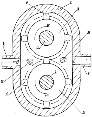 | Figure 5. General view of the hydraulic |
 | Figure 6. Installation of hollow teeth |
 | Figure 7. Installation of a hollow tooth |
This hydraulic machine consists of a casing 1, which has three wheels mounted on the drive shaft 4 and 5 axis and provided with teeth 6. 6 teeth, made of pieces of thin plates, are located in the grooves 7 wheels 3. The housing 1 is provided with a suction pipe 8 and the discharge pipe 9 for guiding movement of the working fluid 10.Gearwheel hydraulic machine operates as follows. When assembling the new or the repair has been previously installed hydraulic advance, made famous by stamping the required number of teeth of a given shape and a module like this, as shown in Figure 7 wide at the ends of segments of thin plates l. Then create the necessary force P and elastically deform the bottom of the tooth 6 to such an extent that he went into space grooves 7 of the arrow A. Applying then the necessary force F, press in widely known in the art to the wheel 3.This technology will allow the tooth 6 a firm foothold on the wheel 3 by the fact that the width of the grooves 7 l less than the distance l teeth. Similarly, the set and the other six teeth on the wheel 3. As soon as the wheels 3 will be installed into the housing 1 to the shaft 4 and os5, and gear hydraulic machine will be ready for use, also widely known method is served by the arrow in the working fluid 10 and a rotating wheel 3 with angular velocity ω.This rotation of the wheels 3 promotes the transport fluid 10 to the discharge nozzle 9, through which the latter received on the arrow on the hydraulic system of hydraulic drive (a drive not shown). Then the process of hydraulic machines, installation and removal of teeth that can be repeated six times, and the dismantling of in reverse order as described above.To evaluate the effectiveness of the proposed design and the definition of its basic characteristics, known technique used is as follows. It is known [2,5,9] that the current value of the amount of fluid  , expelled from the cavity to the pressure
  , the algebraic sum of the volumes displaced and absorbed by its conventional movable walls. One working cycle of the machine corresponds to the angular rotation of the gears move
  (where the number of teeth) with a point of contact mating gear teeth move through their engagement because of what occurs with variable demands
  throughout the cycle, which is subject to a parabolic law. The maximum value
  can be obtained if the point of contact of the teeth located on a straight line passing through the centers of rotation of the gears. The numerical value
  is determined by the relationship:
 Where :
  - radius of the gear projections;
  - radius of the initial circle gear;
  - the angular velocity of gear;
  - width of the gears; t - step engagement.In this case, the uneven flow of working fluid can be determined from the dependence
  where
where  the pressure angle. Important kinematic parameters of gear is also a hydraulic torque applied to the pinion and mean it on drive gear can be determined according to the formula in this case uneven fluid supply can be determined from the dependence:
  where
where  the pressure created by the machine. Some numerical results are the main characteristics of the proposed hydraulic Gear using serial data designs NS-32-2 used in the hydraulic systems of industrial equipment, industrial machines, tractors of various types, etc. [11-13], which
  tooth depth


 and irregularity of supply
  . We define filing machines dependence:
 Since in the proposed design hydraulic teeth are hollow, we assume that the transport of fluid will involve not only the eight volumes tooth space, but on average, seven more volumes within teeth spaces. Underestimated the number of volumes in teeth spaces taken based that through the use of thin-strip from which the teeth are formed and its thickness about their total internal volume is reduced by the amount of internal volume of one tooth. Then a hydraulic feed irregularity is: m off the machine depending on:
 or 14%, compared to the standard machine the figure 1.93 times lower. The calculations also show that, if used in the manufacture of tooth belt stamped with a thickness equal to the internal volume of hollow teeth, compared with the external inter tooth volume decreased by an average of 20%.Consequently, the performance of the hydraulic machine is:
 | Figure 8. analytical model of the tooth |
Analyzing the above it is clear that the proposed hydraulic Gear compared with standard fluid pulsation decreases 1.93 times, productivity increases by 1.8 times and its metal content, by making the hollow teeth, and removal of the metal by milling grooves in the housing the suction and discharge its cavity, below the average of 27%.Analysis of the structure and the work described the proposed technical solutions shows that the teeth of the wheels, made in the form of shells, are complex stress state due to their bending vibrations contribute to their walls are connected, as a rule, with stretching their middle surface. Such fluctuations may significantly reduce tooth reliability, and, therefore, the reliability of the hydraulic machine as a whole.Given this feature, give an estimate of the stress state and characteristics of the pump with the determination of the frequencies of oscillations arising from the elastic deformation of the hollow tooth design scheme using Figure 8.It is known [15] that the strain energy of the tooth as a thin-walled shell shown in Figure 8, can be expressed by the formula:  where, U1 - stretching energy shell;U2 - bending energy of the shell.It is also known [15] that the two types of energies are given;
 | (5) |
where, E - modulus of elasticity of the material;h - the wall thickness of the shell;μ - Poisson's ratio;ε1, ε2, γ12 - strain components middle surface of the shell;χ1, χ2, χ12 - options for changing the curvature of the shell;u, υ, ω - the components of the amplitude displacement point of the shell in the longitudinal, circumferential and normal to the surface directions.Peak value of the kinetic energy of the shell which performs harmonic oscillations with frequency ω1 can be defined by the formula: | (6) |
In this case, the oscillation frequency can be determined by the formula Rayleigh | (7) |
which shows that both the numerator and the denominator of the fraction depends on the choice of displacement u, υ, ω, with the true form of natural oscillations of the report of the stationary value of the formula, and the first natural form - at least. Let R denote the characteristic size of the membrane, and the thickness of its walls through h0 we obtain the following structure: | (8) |
where, λ1 and λ2 - dimensionless quantities depending on the type of amplitude functions u, υ, ω.Analysis of the equation (8) shows that the second term describes the bending energy of the shell (the tooth) and the value of  significantly low, and therefore, minimizing ω12 most significantly decrease energy λ1 corresponding stretching the middle surface of the shell. In our case, by placing the tooth surface is formed between the housing Gear hydraulic machines, the latter is subject only to bending in the vertical plane of the wheel, which tightly and secured with tape to form on her teeth (Fig. 3). Therefore, we can assume that λ1=0 in the absence of high tensile surface of the tooth, ie when ε1=0, ε2 = 0, γ12 = 0. This kind of deformation of the shell is called pure bending. The studies of shell vibrations without stretching the middle of the surface and are described in [20] showed that the frequency determined by the dependence of the same type as those for the plates depending on:
 | (9) |
where, λ - a numerical coefficient;ρ - bulk density of the material.D - flexural rigidity.Analyzing the equation (9) shows that reducing the wall thickness of the tooth that is desire it to zero, the frequency of its vibrations without stretching the medial surface also tends to zero.Because the work is going on in Gear hydraulic transient regime, the loading of its teeth will be characterized by a change in a wide range of dynamic coefficient μ ', is given by: | (10) |
We present a numerical calculation of a vibration frequency of the tooth and dynamic coefficient using software system with the following initial data: E=2•106 kg/cm2, h = 0,175 cm, μ = 0,3, ρ = 0,0007814 kg/cm3 (mark steel 45), λ=0,08, R = 2,1 cm and then in the range of forced oscillation frequencies ω=10÷120 rad/s, we construct the frequency response of the process. Using a known software application package MATLAB 6.5. [19, 20], perform sample calculation to assess the natural vibration of the proposed technical solutions. Text file mu.m procedure in Listing 1. In the first part of the procedure by setting the initial data, and calculate the dynamics of μ. The second part of the procedure displayed in a separate window graphic plot of μ ω / p, limited for clarity of values 0 ... 1.8 on the X axis and 0 ... 5 Y axis using the operator set, which allows you to set the properties of various objects.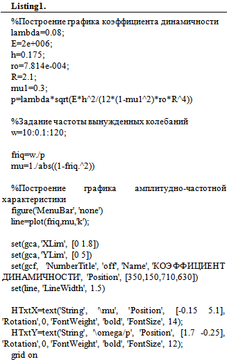 Fragment perform file-procedure mum with calculations natural frequency of the tooth under the above initial data parameters is shown in Figure 9.
 | Figure 9. program window |
Presented in Figure 10 plot, built for long-term gear pump, shows that when the perturbation frequency ω to the natural frequency of the order of p 48.6 rad / s (7.74 Hz) dynamic factor increases, and its maximum is attained at a ratio  which is characteristic of the resonant mode could cause a permanent deformation of the teeth or their destruction. In this case, from the presented in Figure 4. graph also shows that the most dangerous zone in terms of growth of dynamic loads, when μ = 1,5 is the range of the
  . Whereas in overcoming this area, about when ω = 100 rad / s (16 Hz) and
  which is characteristic of steady state operation of pump, the resonance phenomenon of teeth will be deleted.
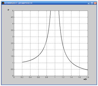 | Figure 10. resonant schedule |
Currently, due to the development of information and computer technology with the use of modern software developed by the international community, the authors plan to carry out works on the calculation of the stress state and performance of new technical solutions, which are developed at the University through improved design and modernization of hydraulic gear.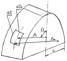 | Figure 11. Shell design scheme |
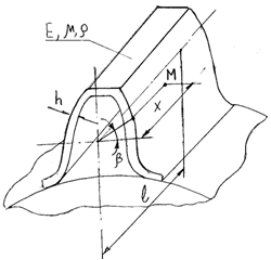
For the calculation of the stress state of the hollow tooth and its stability, for example, the driving wheel with its interaction with the working fluid and the other tooth driven gear, use the known method of determining the stresses in symmetrical shells on without bending theory [15]. In our case, we represent the tooth as a symmetrical shell wall thickness h (Figure 11 and Figure 12), having a radius of curvature of the meridian arc middle surface ρm with the second principal radius of curvature of the normal section perpendicular to the meridian arc denoted ρt. The last segment is reached between the normal and the medial surface of the axis of symmetry. Specified radius ρm and ρt are generally a function of the angle θ is located between the normal and the axis of symmetry. We extract from the shell (Fig. 12), the element ds1, ds2 and assume that the face of such an element any stress σm and σt while the former is a meridional stress directed along the arc of the meridian, and the second circle. Consequently, the item will arise related efforts σm h ds2 and σt h ds1 (12).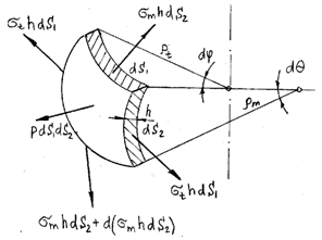 | Figure 12. Analytical model of a shell element |
Projecting such efforts on the normal get the following equation of statics: | (11) |
Given that  and
and  and substituting these relations in equation (11) the following relationship is called the Laplace equation:
  from which you can determine the resultant of the external forces acting on the shell (in this case, the tooth wheel) depending on:
 | (12) |
At the same time, knowing the numerical value of the resultant of the external forces acting on the membrane can be calculated meridional stress σm.It should be noted that the described force loading of the tooth wheel is a hollow shell, you may lose the stability of the latter and it can take, for example, the form shown in Figure 13.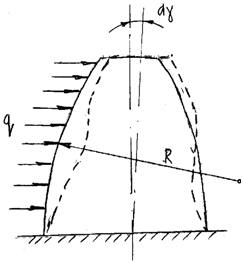 | Figure 13. analytical model of stability of the tooth |
 | Figure 14. Element of the design scheme |
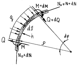
We separate from the tooth become unstable elementary space length ds (Fig. 14), and denote its local radius of curvature in ρ, assuming that this value is not significantly different from the initial radius of curvature R of the tooth. The external load q in the cross sections of the tooth any normal forces and bending moments with the normal force can be composed of two parts: the term N0, which originated in the cross sections of the tooth to the loss of its stability, and the term of N which is a small change in the normal force due to the bending forming surface of the tooth. Then, using the equilibrium condition and designed all the forces in the direction normal obtain three equations of the form: | (13) |
But since the time of M also depends on the change of curvature of the surface of the tooth, then you can define it as follows: | (14) |
where, χ - characteristic curvature of the surface of the tooth.Solutions of equations (13) and (14), a known method [15] allow us to obtain a formula for determining the critical force: | (15) |
Here is an example of the numerical calculation of the basic parameters of the power loading and stability of the sheath of gear tooth proposed hydraulic machines, using the above method of calculation and the data series the pump NSH 32-2 widely used in hydraulic transport machinery, metal working equipment, etc., in which the radius of the initial circle gear  tooth depth
  face width of a tooth
  number of teeth step engagement
  , speed gears
  and irregularity of supply
  . The working fluid pressure is p = 9 MPa and a tooth made of steel strip thickness h = 2,0 mm. Therefore the surface of the tooth will be attached to the load P = Ps = 90 • 0,8 • 1,6 = 115 kg = 1.15 kN. Numerical values stress σm, resulting in tooth plate thickness h = 2,0 mm using the formula (12):
 where, r - half feet at the base of the tooth is 0.9 cm;θ - angle located between the normal and the axis of symmetry is assumed to be 50.As a material for the manufacture of steel teeth take 40X to GOST 4543-71, followed by heat treatment improvements for which the permissible stresses are [σ] = 415 MPa. We see that in our case the design stresses σm = 127,1 MPa lower than 3.3 times of the accepted value, therefore, the strength condition is satisfied.Now check the stability of the tooth, also assuming that the load is applied to it at 1.15 kN using the relation (15):
 where, E - modulus of elasticity, kg/cm2;J - the axial moment of inertia of the tooth, cm4.Analyzing the results obtained show that the critical force is 3,16·102 N and then the safety factor ny be 316/115 = 2.8. Consequently, the loss of stability of the tooth in the process of gear hydraulic load 1,15·102 N excluded. The presented method of calculation, to a first approximation, can be used in the synthesis and design of a wide class of hydraulic gear, the teeth, which are in the shape of shells and used in the hydraulic systems of transport, agricultural and road-building machinery, as well as in various designs industry-standard and non-standard equipment engineering companies, both in our country and abroad.It should also be noted that the conditions hydraulic gear used in hydraulic machinery and equipment shall meet the main criterion of performance cars - reliability. Under reliability understand - property is available within a specified time or a given operating time to function, keeping within limits operational performance. Product reliability, determine their reliability, durability, maintainability and persistence. It is clear that the proposed construction of gear hydraulic machine must be repaired in conjunction with the machine on which it is mounted on repair enterprise, which is a variety of engineering and performed in accordance with specifications repair machines (units, assemblies, parts, etc.), loss normal operation, but repairable, and performing the role of original pieces for this production. In contrast to the repair machinery production includes specific processes: cleaning, disassembly, Troubleshooting and repair of machine elements. The consumer is essential to the repair of vehicles, as well as their replacement parts would be short-lived as little ballast works, ie of the machine with the minimum cost of labor, materials and energy to their disassembly and cleaning, removal of exchangeable design and removal of short-lived non-structural elements. Based on the cost, appropriate ballast works in the repair, maintenance or replacement of structural elements of machines, quantify their maintainability characterized factor maintainability.Factor maintainability
  machine can be defined as the ratio of the average cost of labor, energy and materials required for the introduction of the machine follows and renewable elements, to the sum of labor, energy and materials on its disassembly and cleaning, along with the assembly, adjustment and renewal of other non-structural elements in the relationship:
 or the ratio of value
  Where
Where  and
and  -Average life and value, corresponding volume of ballast works in maintenance, repair or replacement of short-lived structural elements.From the analysis of the structure of the machine change life for the battery life implies the possibility of an adjustment to the assessment of machinery on specific indicators, particularly on their specific metal and value, which is also one of the most important characteristics for the repair of vehicles.To determine the serviceability of the proposed technical solutions and standard Gear hydraulic model NSh-32-2 is used in hydraulic systems, such as wheeled tractors MTZ-80, which


 , the analysis of financial activity "MUZHERP" Yelets "for the period 2005 to 2006, where a renovation of these pumps. The analysis showed that the average cost of labor, energy and materials to repair a pump SS-32-2 on average QiC = 5659rub and ballast of equal qiC = 2850rub. Consequently, the coefficient standard hydraulic maintainability is FP = 0.66. For the proposed construction of a hydraulic repair costs are QiC = 4230rub, and at a cost of ballast works qiC = 1050rub maintainability index was equal to the FP = 0.8. It is evident that the design of hydraulic gear-made according to the patent (RU2341686) ratio is higher maintainability, which shows the efficiency of the solution in practice.
4. Results of the Study
Analyzing the above, we can draw the following conclusions. So analysis available today different types of hydraulic gear is non-compliant because of low productivity, high ripple fluid supplied to the executive bodies of machines and metal and so the development of the past as inventions RU2338926, RU2341686 RU2246637, RU2269031 sufficiently high efficiency solution allows eliminate these disadvantages is very important. Analytical studies have shown that the exclusion of these shortcomings is through the implementation of gear teeth gear hydraulic hollow, allowing a comparison with serial designs reduce fluid flow pulsation 1.93 times, increase productivity by 1.8 times, while its metal for through the implementation of hollow teeth, and removing a portion of the metal by milling grooves in the housing of the suction and discharge its cavities, reduce by an average of 27%. At the same time, possibly with the elastic deformation of the hollow tooth moving fluid under pressure to ensure the sustainability of the latter with the safety factor equal to ny = 2,8, and given the strength of the teeth at rated voltage σm = 127,1 MPa, which was lower by 3.3 times from the accepted value, therefore, the strength of their condition will be satisfied.
5. Conclusions
Results of the study recommended companies both domestic and foreign engineering, operating and manufacture various equipment for its intended purpose, to study the proposed technical solutions and the opportunity to continue their implementation in practice. To select the appropriate material for the manufacture of hollow teeth, the calculation of their strength and stability, and the development process, depending on the size and destination used software for computers, which was tested in the examples shown above. It should also be noted that the design parameters determined by this method are approximate and can not be recommended for instant use, and therefore for the final evaluation of the effectiveness of the proposed technical solutions necessary to conduct extensive testing of the performance and efficiency.
References
| [1] | Hydraulics, hydraulic and hydraulic drives: textbook for engineering schools / T. Bashta, S.S. Rudnev, B.B. Nekrasov, etc., 2nd ed. Pererab.-M.: Engineering, 1996.-423s. |
| [2] | Bashta T.M., Engineering hydraulics. - Mashinostroenie, 1989. – 672 pages. |
| [3] | Bashta T.M., Hydraulic and hydro-pneumatics. - Mashinostroenie., 1985 – 376 pages. |
| [4] | Dolgachev F.M., Lake V.S., Fundamentals of hydraulics and hydraulic drive. - Moscow: Publishing House of Literature on construction. 1996. – 215 pages. |
| [5] | Chuprakov Y.I. Fundamentals of hydraulic and pneumatic actuators. - Mashinostroenie, 1986 – 159 pages. |
| [6] | Reference on hydraulics, hydraulic and hydraulic. / Ed. BB Nekrasov. - Minsk, 1985-234 pages. |
| [7] | Uginchus A.A., E.A. Chugaeva - Hydraulics. -Leningrad, Publishing House of the literature on the construction, 1991 – 349 pages. |
| [8] | Machine tools. Tepinkichiev V. K., Krasnichenko L.V. etc. - M.: Engineering, 1996-472 pages. |
| [9] | Ermakov V.V. Bases for design of hydraulic drive. -M.: Mashgiz, 1975-186 pages. |
| [10] | Shashin V. Fluid. Textbook. for tech. Universities. - Graduate School, 1990.-384 pages. |
| [11] | Barsky I.B. Design and calculation of tractors. Textbook for high schools in the specialty "cars and tractors." - 3rd ed., Rev. and dop.3 - Mashinostroenie, 1987 – 335 pages. |
| [12] | Zabegalov G.V., Roninson E.G., Dozers, scrapers, graders. Tutorial for prof. those. schools. - Moscow High School, 1991-330 pages. |
| [13] | Karpenko, A.N., V.M. Halansky Agricultural machinery. - 6th ed., Rev. and add. - Moscow Agropromizdat, 1989-527 pages. |
| [14] | Nekrasov B.B., Belenkov Y.A. Pumps, hydraulic actuators and hydraulic transmission. MAMI, 1996.-126 pages. |
| [15] | Feodosyev V.I. Strength of Materials. / Moscow: Nauka, 1990. – 544 pages. |
| [16] | Hydraulics, hydraulic and hydraulic drives: textbook for engineering schools / T. Bashta, S.S. Rudnev, B.B. Nekrasov, etc., 2nd ed. Pererab.-M.: Engineering, 1989.-423 pages. |
| [17] | Slivinskiy E.V., Zaitsev A.A., A.N. Slivinskaya The new pump hoist trucks. "The automotive industry." № 2.M.: Engineering, № 2, 2006.-18 pages. |
| [18] | Slivinskiy E.V., Zaitsev A.A., Prospective Gearwheel hydraulic machine. "Tractors and farm machinery." № 4, Mashinostroenie, 2007.-20 pages. |
| [19] | Anufriev I.E., MatLab tutorial 5.3/6.h. - St.: BHV-Petersburg, 2002. - 736 pages.: Ill. |
| [20] | Iglin S.P., Mathematical calculations based on MATLAB. - St.: BHV-Petersburg, 2005. - 640 pages.: Ill |
| [21] | Avrunin G.A. Market Overview of hydraulic / / Tractors and farm machinery. - 2005, № 3. |
| [22] | Sveshnikov V.K. Review of the Russian market of hydraulic equipment. Motors / / Drive Technology. - 1997, № 6. |
| [23] | Shamshur A.Z., Grigoriev V.P. Quality and innovation - the basis for the further development of the production of hydraulic drives / / hydraulics and pneumatics. - 2003, № 11. |
| [24] | Axial Piston Pumps, Series 90, Technical Information. Catalogue of companies Sail er-Sunst rand. 1999. |
| [25] | Doroshchenko V.I., Glush M.G. New hydromachine GSK.TB GA / / The drive and control. - 2001, № 9. |
 Abstract
 Reference
 Full-Text PDF
 Full-text HTML