E. V. Slivinsky1, T. E. Mitina2, S. Y. Radin3, E. A. Suzdalskaya2, D. N. Klimov2
1Doctor of technical science, Mechanical Technological Faculty, Elets state University I.A. Bunin, Elets, 399770, Russia
2Elets state University I.A. Bunin, Elets, 399770, Russia
3Candidate of technical science, Elets state University I.A. Bunin, Elets, 399770, Russia
Correspondence to: E. V. Slivinsky, Doctor of technical science, Mechanical Technological Faculty, Elets state University I.A. Bunin, Elets, 399770, Russia.
| Email: |  |
Copyright © 2012 Scientific & Academic Publishing. All Rights Reserved.
Abstract
This article presents information related to the development of promising design cradle suspension for passenger cars, ensuring smooth running of railway rolling stock. Grounded goals and objectives of the study and based on an analysis of numerous domestic and foreign literature and patent sources on this problem developed as inventions cradle suspension damping design, able to absorb vibration energy of passenger cars to the process of their movement along the track. The design procedure was developed physical and mathematical models to determine the basic geometric and kinematic parameters of the above structure. Results of the study recommended research and industrial structures in the area of car building for the purpose of further study and possible implementation in practice.
Keywords:
Rama, Cart, Wheel Pair, Nadressorny Beam, Torsion, Torsional Rigidity
Cite this paper: E. V. Slivinsky, T. E. Mitina, S. Y. Radin, E. A. Suzdalskaya, D. N. Klimov, To the Calculation of Rational Parameters of Promising Spring Suspension for Passenger Cars, International Journal of Traffic and Transportation Engineering, Vol. 2 No. 4, 2013, pp. 55-66. doi: 10.5923/j.ijtte.20130204.01.
1. Introduction
It is known[1-3], which in trucks passenger cars КВЗ-ЦНИИ (Figure1), which is widely used in practice, apply the return of the device, which serve both to mitigate the side shocks arising from creeping of the crests of the wheels when the movement of wheel pairs for straight sections of the road and at the entrance of the car in curves, as well as for the return of the rejected body under the action of transverse forces in the middle.Return the devices that are used in trucks cars are of two types, which differ by the principle of action and constructive implementation. The first type include devices that returns the power of which is created due to the use of force of gravity of the body, acting on the cart. To such devices include design, with rollers (roller), placed between the inclined planes (Fig. 2). With a cross rejection of the cart on the body occurs returns the power N, not depending on the deviation of the cart. If the rollers (roller) instead of inclined planes place in the oval (cylindrical or executed by the special profile) cavities (system V.I. Babina), that returns the power N will increase according to the specific law with increasing transverse deviations carts in connection with the increase of the angle of α from zero (middle position) and a maximum value (the maximum deviation of the cart). The first type, which returns the power of is created due to the use of force of gravity of the body, is also lyulechny suspension (Figure3). In case of horizontal deviation nadressorny beams 4, situated on the elastic elements 3, will change the tilt lyulechny pendants 2, which will cause the appearance of a horizontal table effort.Cradles are with vertical and inclined pendants 2. Vertical lyulechny suspension in case of deviation remain parallel between themselves, and the nadressorny beam when it is parallel to the original position. In the case of inclined lyulechny pendants 2 creates a large amount of restoring force, which depends on the initial angle of angle, but it is undesirable tilt nadressorny beams 7, and sometimes skewed and torsion of the car body. The second type returns the device returns the power through the use of transverse elasticity of elastic elements spring suspension. In modern trucks of freight cars, for example, the functions return devices perform springs, returns the strength of which is proportional to the magnitude of the horizontal elastic deformation. In trucks passenger cars role returning devices together with the cradle perform elastic strings, as well as pneumatic and other types of elastic elements of the suspension. It should be noted that the design люлечного suspension may not in an automatic mode to change their characteristics associated with the creation of the forces of resistance in contrast to the dynamic forces causing the angular displacement of the cradle, which significantly affects the dynamics of the car and its smooth running.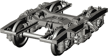 | Figure 1. General view cart КВЗ-ЦНИИ |
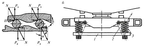 | Figure 2. Return the device |
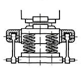 | Figure 3. Cradle |
2. The Aim of the Research
Given the importance of the problems directed on creation of design of trucks for passenger cars, which allows to significantly increase the smoothness of the latter, the objective of this study is:1. Development of люлечного the suspension of passenger cars, allowing in an automatic mode and efficiently produce vibration dampening of railway carriages in accordance with the requirement of GOSSTANDART 12406-66, in which stipulated rational parameters to ensure the comfort of passengers.2. Development of the scheme of this device allows to produce analytical studies of fluctuations and force loading of its structural elements and carried out with the help of a mathematical model of calculation of rational kinematic and geometric parameters.3. The use of computer programs, takes into account the diversity of structures of passenger cars and allows to make calculations of the parameters of the element base of the proposed design lyulechny suspension.
3. Methods
In view of the foregoing, in Elets state University I.A. Bunin, a promising lyulechny suspension for passenger cars recognized invention (RU2432281).Figure 4 shows the principle of spring suspension passenger carriage, and in Figure 5 – of its kind in the cross-section of the AA.The technical nature of this design is that lyulechny suspension linked elastic rods (torsion) with the opportunity to change its torsional rigidity in the automatic mode depending on the value of dynamic loads arising in the movement of the carriage caused by micro or macro roughness of the way. To investigate the efficiency of such a structure and its force loading the calculation diagram (Figure4) spring suspension allows the study of oscillation and force loading of the structural elements in the conditions approached to operational.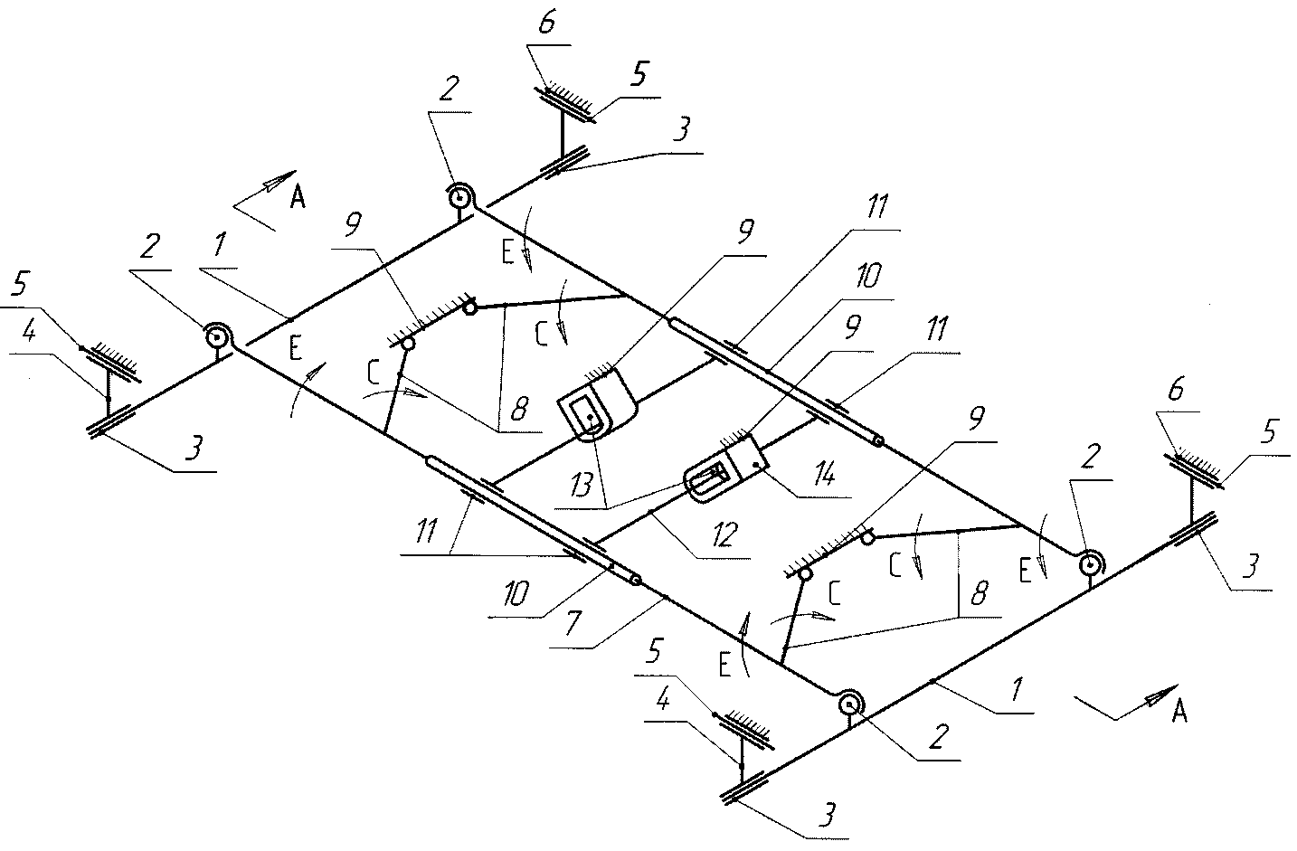 | Figure 4. Schematic diagram of the suspension |
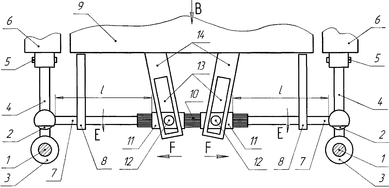 | Figure 5. Cross-Section of the suspension on AA |
In such cases as the basis used viscous-elastic model Feucht-Kelvin (Figure 6).On the diagram shows how the weight of the car body mк interconnected through nadressorny beam 1 with torsion structural elements of the cradle, with the torsional stiffness of the Кφ and spring set of linear rigidity С2 and, between body mass mк is located hydraulic vibration damper with the coefficient of damping α. The structural elements are interconnected with the frame of the trolley, which through elastic elements with linear rigidity С1, is connected to the wheel pair 3 wagon.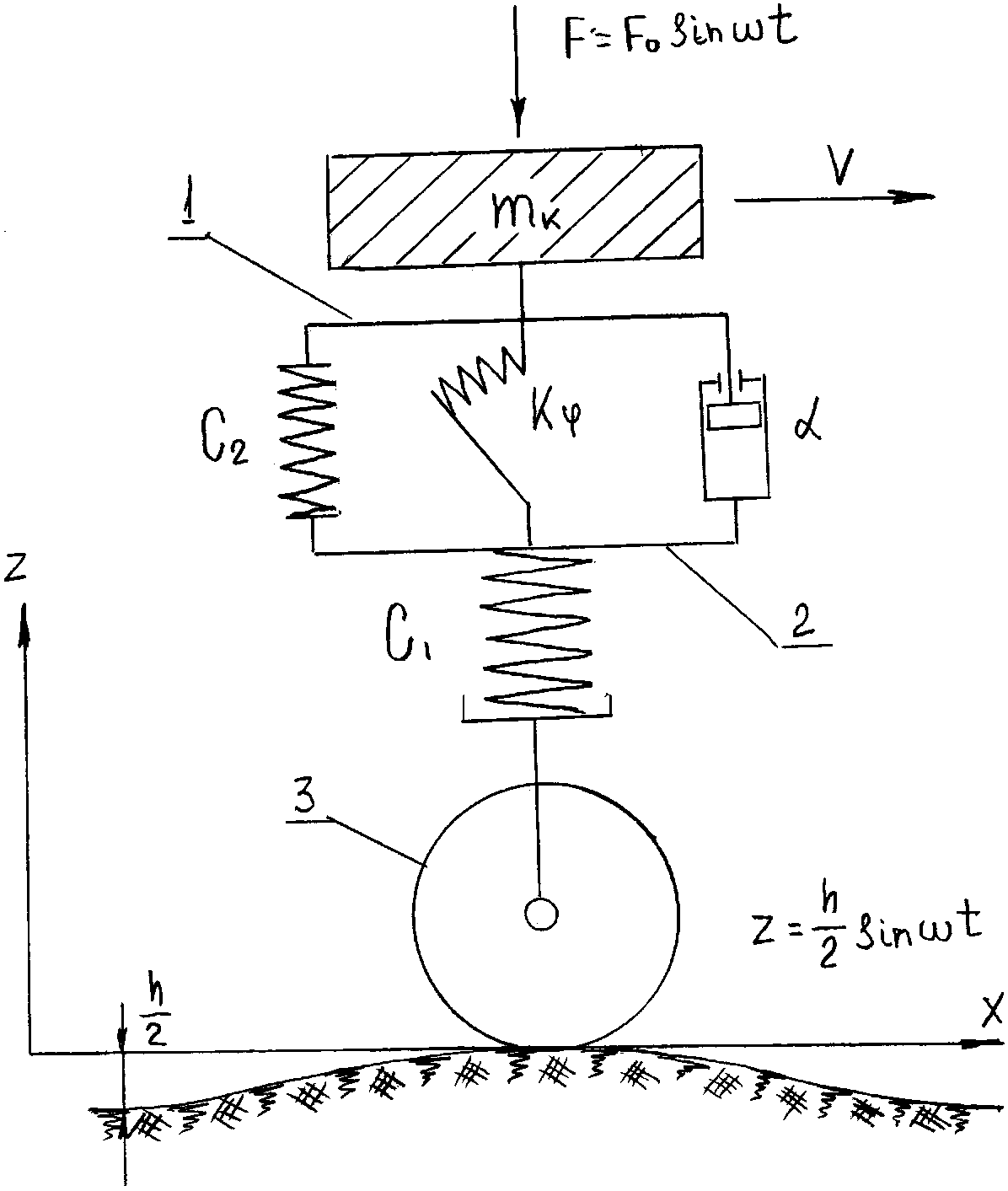 | Figure 6. Scheme |
At drawing up of the mathematical model to the specified settlement scheme adopted the following assumptions:1. Not taken into account bending oscillations of the rod, and other parts of the hydraulic damper.2. Coefficient of friction of mating surfaces is taken constant.3. The law of excitement due to the irregularities of the micro - and macro-profile conditional pavement changes in time according to the harmonic law.4. Is not taken into account the gyroscopic effect of a rotating mass of wheels, as well as air resistance when its translational motion.5. The processes occurring in the hydromechanical damper, believe isothermal to the specified coefficients of viscosity of the working body.6. Movement of damped mass considered relative to the coordinate system ХОУ, situated at the level of the road and moving along it with a constant speed.7. To reflect the movement of the piston and the rod of the shock absorbers on a system of reference for the longitudinal oscillations, applied inverse form of the assignment of coordinates, and with torsional direct.8. Vectors of dry friction forces in the forward kinematic pair the «piston - working cylinder» were heading in the opposite direction relative to the coordinate system.When forming of the mathematical model used by the equations of dynamics, theory of elasticity and hydromechanics. As the base of the calculation of the ratio was adopted by the equation of motion of a concentrated mass mк, which accordingly to the cases of power, kinematic and mixed excitation is of the form: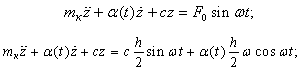 | (1) |
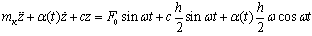 ,where, mк - the sprung mass;с - the stiffness of the elastic element of the suspension;α(t) - the variable damping factor;F - dynamic loading;z - movement on the vertical axis;h - the height of the roughness of the way;ω - the oscillation frequency of the body.According to the settlement scheme (figure 6) shows that the elastic elements with linear rigidity С1 and С2 are consistently relative to each other and therefore a member С included in the equations (1) will be characterized by the dependence 1/С = (1/С1+ 1/С2). At the same time, an element with a torsional stiffness Кφ is located parallel to the element with the rigidity С2 and so that the level of hardness for the latter may be written in the form СΣ = С2 + Кφ. Therefore the value С can be determined by The dependence of С = 1/С1 + 1/С2 + Кφ. At the same time, taking into account, that the dimension of the linear hardness and the torsional different, in equation (1) should not substitute the dependence С = 1/С1 + 1/С2 + Кφ, and the formula С = 1/С1 + 1/С2 + СТС or С = 1/С1 + 1/С2 + СТД depending on the study of the motion of the wagon or its settling, where СТС and СТД torsion rigidity respectively for static or dynamic loading of spring kit.In this case, you select the linear displacement of the point of contact of the levers 8 of elastic rods 7 are in fact torsion bars and contact with nadressorny beam 1 (Figure 4), under the influence of the mass mк, respectively, in statics and dynamics that can be defined according to the formula:
 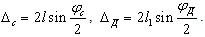 As a result, for these movements can determine the stiffness of torsions, respectively, according to the formula:
  ,
,  As under the action of swirling moment there is a net torsion of a rod torsion, the numerical value of the absolute angle of the torsion can be determined depending on:
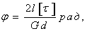 where, l - the length of the working part of the rod of the torsion;d - diameter of the torsion;[τ] - admitted by the tangential stresses.Angular movement of the tip of the lever shaft torsion in the direction of the workload as well:
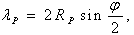 where RP - the length of the lever of the torsion.In the diagram (Fig. 4) as well as in the actual design of the carriage there is a hydraulic vibration damper and so in equations (1) is taken into account the damping characteristic
  . It is known[2]that the damping factor
  depends on the hydraulic resistance in the channel of the piston shock absorbers, the viscosity of the working fluid flow turbulence and can be determined by the formula:
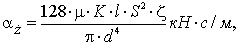 | (2) |
where, μ - the coefficient of dynamic viscosity;l - length of the channels in the bucket;S - the area of the piston;d - equivalent to the diameter of the channel;ζ - coefficient of hydraulic losses in the power channel;K - generalized coefficient, taking into account the influence of turbulence of the flow and local resistance on the bandwidth of the working fluid of the shock absorber.
4. Results
 | Figure 7(a). Listing file-functions at force excitation |
 | Figure 7(b). Schedule of the oscillation process |
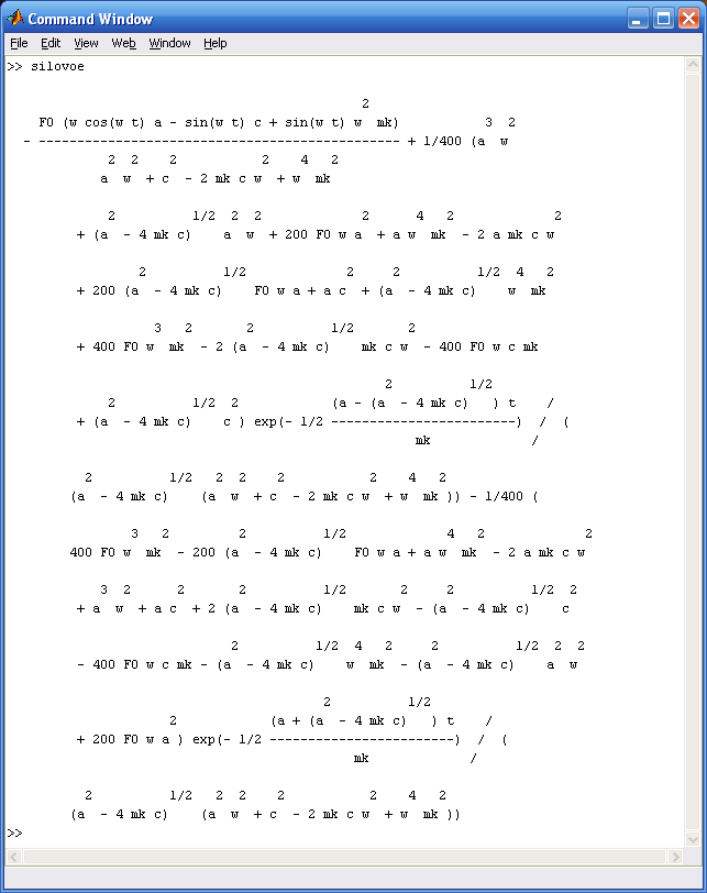
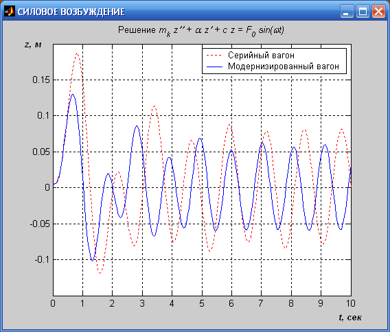
To assess the effectiveness of the proposed technical solution is completed analytical and numerical decision submitted by the differential equations for a serial (modernized) passenger car several posts with the following characteristics: the sprung mass of the mk = 434000 N; dynamic load applied on a cart wagon F0 = 720000 N; damping factor hydraulic damper fluctuations α = 440000 N∙s/m; the stiffness of the elastic element pendants c = 2280600 N/m (c =3683200 N/m); the circular frequency of the oscillations of the body ω = 5 1/s (ω = 6 1/s); the height of bumps the way h = 0,15 m. The dynamic process is considered for the period of time Δt from 0 to 10 seconds.The analytical solution obtained using the dsolve built-in package ToolBox Symbolic Math, input arguments, which are the line to the equation, initial conditions, and the independent variable for which is the default time variable t. To display a character expression of solution of differential equations used function pretty.Numerical solution of a set of differential equations with initial conditions, i.e., the Cauchy problem, carried out with the help of built-in functions of MatLab, called solvers. For the above equations used solver ode45, which is based on the method of Runge-Kutta of the fourth and fifth order of accuracy. The input arguments solvers are: the name of the file functions in apostrophe, vector with an initial and a final time value observations of the movements and the vector of initial conditions. Output argument two: the vector of values of time and a matrix of values of unknown functions.Scheme of location of the numerical solution consists of the following stages:1. Adjusting the differential equation to a system of differential equations of the first order.2. Writing a special file of functions for the system of equations obtained. File-function must have two input arguments: the variable t, which is the differentiation, and the vector, the amount of which is equal to the number of unknown functions of the system.3. Call solver ode45.4. Visualization of the obtained results.In accordance with the above described scheme were obtained analytical and numerical solution of the three types of excitation of oscillations for the standard and the upgraded node.In the case of forced excitation of an analytic solution of a differential equation 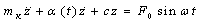 with initial conditions
 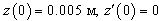 will be as shown in Figure 7(a), and the numerical solution presented the schedule of the oscillation process (Figure 7 (b)).To obtain the presented solutions were written file-functions that use solver ode45, which implements a numerical method Runge-Kutta of the 4-th and 5-th order. For the possibility of using such solver differential equation is transformed into the system of equations:
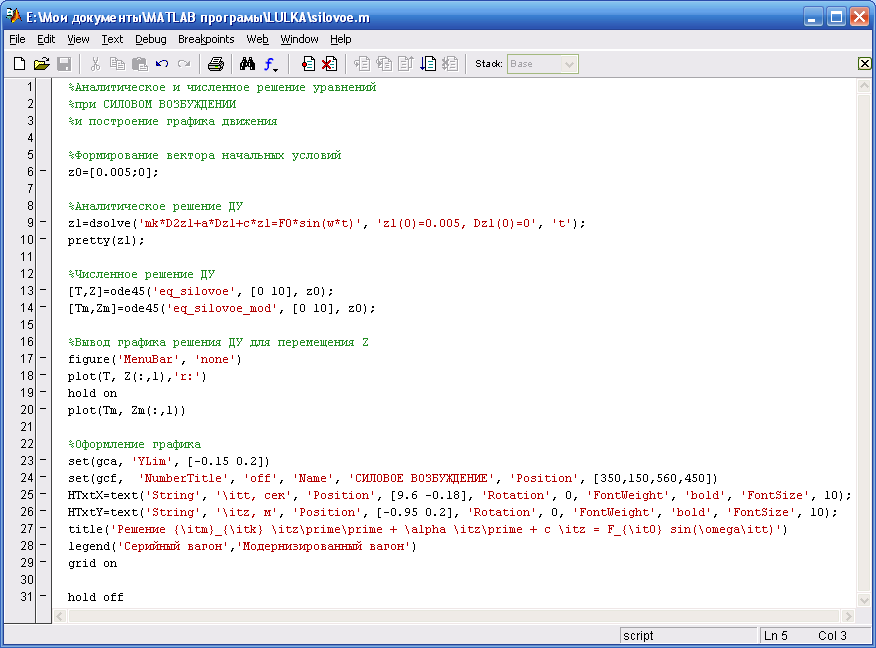
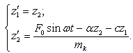 Listings of file functions with the power to initiate the series and the upgraded node presented in figure 8(a) and 8(b), respectively. They set the values of the parameters involved in the equation. A third file is a function contains the analytical and numerical solutions of the equation and output commands and design of the chart (Figure 8(c)).
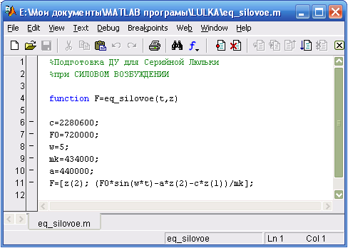 | Figure 8(a). Listing file-functions for serial node |
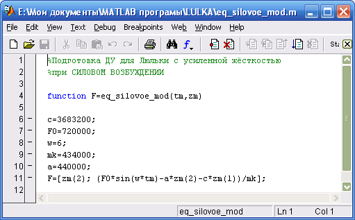 | Figure 8(b). Listing file-functions for the upgraded node |
 | Figure 8(c). Listing output commands and design graphics |
When the kinematic excitation of an analytic solution of a differential equation with initial conditions
 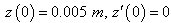 will be as shown in Figure 9(a), and the numerical solution presented the schedule of the oscillation process (Figure 9 (b)).
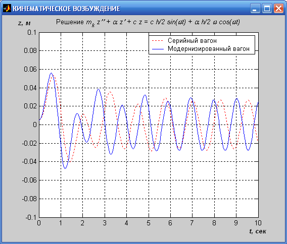
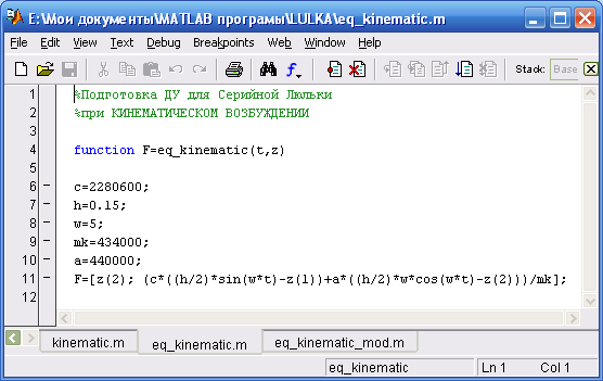
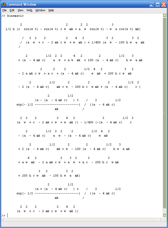 | Figure 9(a). Listing file-functions at kinematic excitation |
 | Figure 9(b). Schedule of the oscillation process |
When preparing to use a solver differential equation is transformed into the system of equations: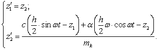
 | Figure 10(a). Listing file-functions for serial node |
 | Figure 10(b). Listing file-functions for the upgraded node |
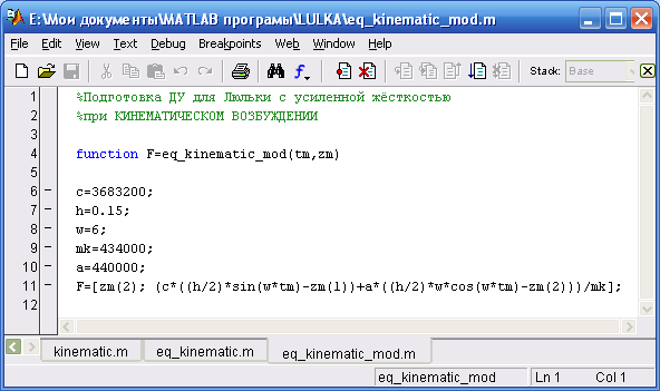
Similarly the occasion of forced excitation in figure 10(a) and 10(b) presents listings of file-functions at kinematical excitation for the serial and the upgraded node respectively, and a third file-function contains the analytical and numerical solutions of the equation and output commands and design of the chart (Figure 10(c)).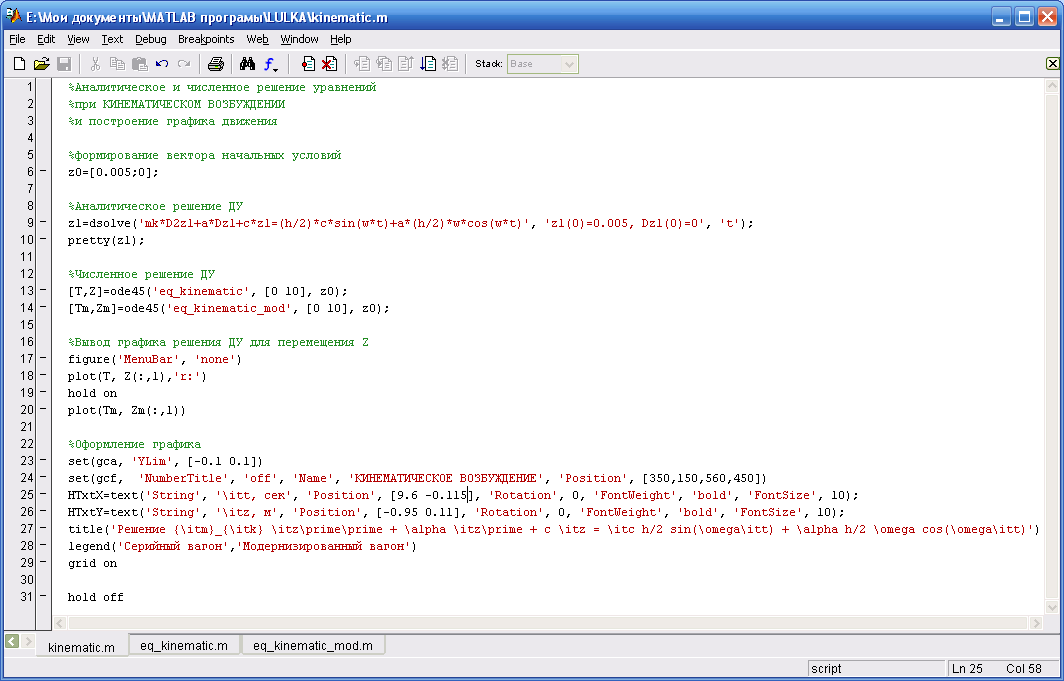 | Figure 10(c). Listing output commands and design graphics |
For mixed excitation of an analytic solution of a differential equation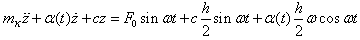 with initial conditions
 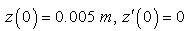 will be as shown in Figure 11(a), and the numerical solution of the presented schedule of the oscillation process (Figure 11 (b)).
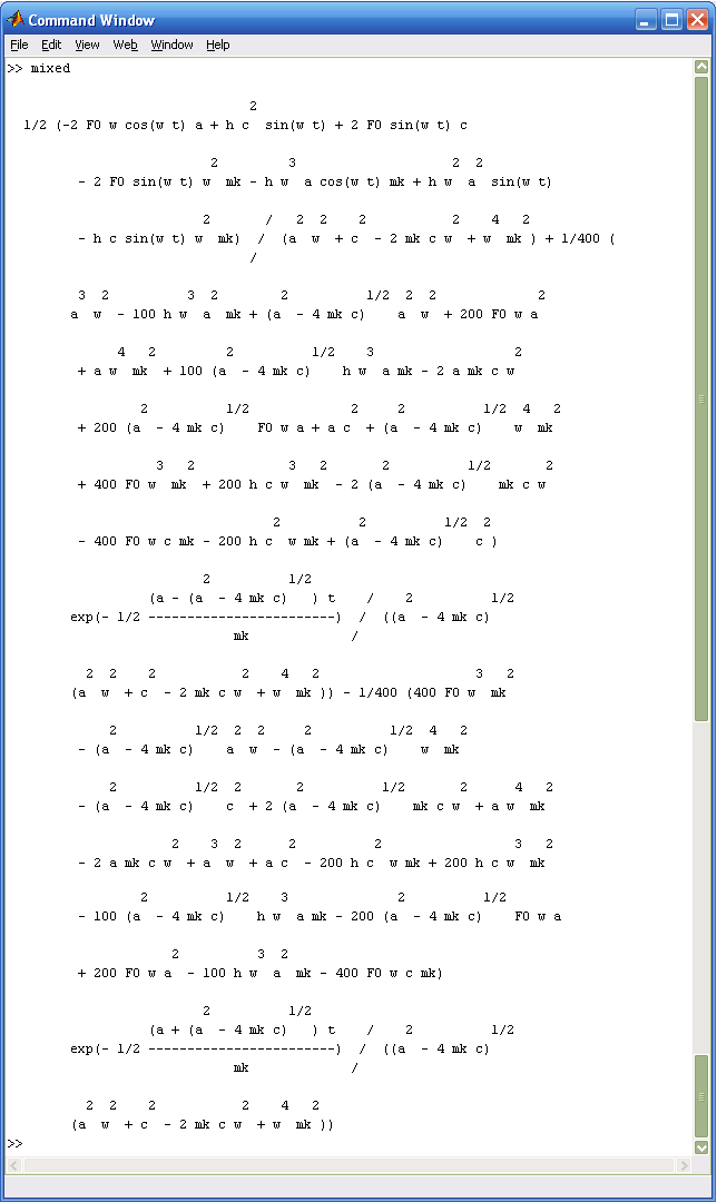 | Figure 11(a). Listing file-functions at mixed excitation |
Before reception of the decision of differential equation is transformed into the system: 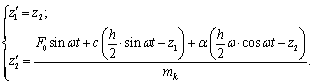 Similarly to previous cases in Figure 12(a) and 12(b) presents listings of file-functions with mixed excitation for the serial and the upgraded node respectively, and in Figure 12(c) - listing-file function call solver and design graphics.
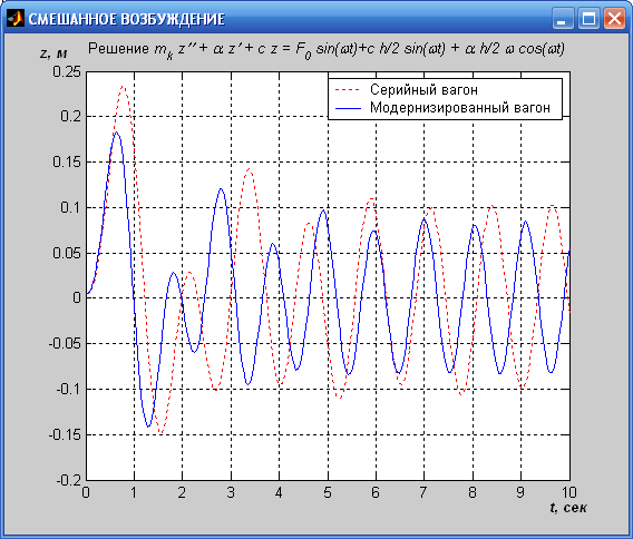 | Figure 11(b). Schedule of the oscillation process |
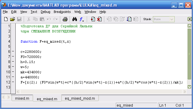 | Figure 12(a). Listing file-functions for serial node |
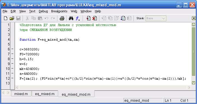 | Figure 12(b). Listing file-functions for the upgraded node |
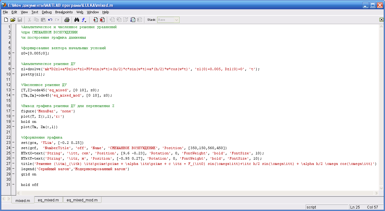 | Figure 12(c). Listing output commands and design graphics |
5. Discussion and Conclusions
Analysis of the obtained results for the three characteristic of the above equations of motion of the carriage shows that in the first case, the power of excitation for the serial car amplitude of fluctuations of its body in an average of 0,08 m, while for the upgraded car this indicator is 0,06 m. In the second case, the kinematic excitation amplitude of the oscillations of the body for the serial car in the average is 0,035 m, while for the upgraded its value is slightly lower and is 0,028 m. And in the third case, when mixed excitation amplitude of oscillations, respectively, for the serial and modernized cars in average respectively are between 0,1 m and 0,07 m.It should also be noted that the frequency of oscillations of the body compared cars also differ between themselves and if for the serial car circular frequency of forced oscillations is on average 8,5 1/s (1,35 Hz), then for the car, equipped with a cradle, performed by the patent RU2432281, this value lies in the range from 6,0 to 6,2 1/s (0.96-0,99 Hz).It is known[1] that for the resonance mode of amplitude of oscillations of the sprung masses can be determined respectively by the dependence: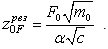 From this expression shows that depending on the nature of the application of perturbation of the requirements to the stiffness of the suspension is changed so that to reduce the fluctuations in spring mass in a resonant mode to increase the stiffness of the suspension.It is also known[1] that the most important operational criterion for assessing the performance of the railway rolling-stock is a measure of smoothness of motion, especially for passenger cars, where the comfort of the passengers is of critical value, which can be determined depending on:
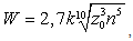 ,where k - coefficient taking into account the influence of the frequency and direction of oscillations on the fatigue of passengers is selected on the average equal to 0,85[2];z0 - the value of the resonance amplitude;n - the average value of the frequency of oscillations of the body of the carriage when his galloping, bouncing, the rolling and wobble.And then for a formula of resonant mode of motion, serial and modernized carriages indicator of smoothness of motion for spring suspension with serial and proposed spring suspension was respectively equal to Wser = 3,76 and Wmod = 3,12. At the same time it is known[1]that the smoothness of the passenger car is the better, the less is the value of W and according to Gosstandart 12406-66 valid her limit for this type of rolling stock is the value of W = 3÷3,25. Comparing the indicators listed above can be seen that due to the use of the proposed technical solution smooth running of the above passenger railcars in comparison with the serial corresponds to GOSSTANDART , increases and thus allows to improve comfortable conditions for passengers.The results of the research are recommended for further study, further development and possible implementation of perspective design of lyulechny the suspension of passenger cars at the enterprises of heavy mechanical engineering and «Russian Railways» is serially producing, repairing and exploit the passenger and special, for example, refrigerated wagons, and also in systems of high-speed ground transportation of domestic and foreign production.
References
| [1] | Vershinsky S.V. etc. Dynamics of the car. - M.: Transport, 1982. - 304 p. |
| [2] | Chelnokov I.I. etc. Quenchers of fluctuations of cars., 165, 1963. |
| [3] | Chelnokov I.I., Koshelev V.A. Setting parameters spring suspension of passenger cars on the basis of a study of the vertical oscillation. L.: Transport., 1966. (Proceedings of ЛИИЖТ vol. 255) 3-27p. |
| [4] | Structure and dynamics of diesel locomotives. Ed. 2-e and add., under ed. Ivanov V.N. - M.: Transport, 1974. 260p. |
| [5] | Babakov I.M. Theory of oscillations. M.: The publishing house Nauka, 1968. 310p. |
| [6] | Feodosiev V.I. Resistance of materials. M.: SHKOLA, 1980. 326p. |
| [7] | Savin L.A., Slivinsky E.V. Element base trailed vehicles (Monograph). - Orel: Orel GTU, 2008. - 296 p. |
| [8] | Slivinsky E.V., Savin L.A., Radin S.Y. Ways of improving the chassis of vehicles: monograph - Yelets: ElSU I.A. Bunin. 2009. – 240p. |
| [9] | Slivinsky E.V. Modernization and ways of improving the train vehicles. (Monograph) LAP LAMBERT Academik Publishing CmbH & Co. KG Dudweiler Landstr. 99, 66123 Saarbrucken, Germany 2011. 471 p. |
| [10] | Slivinsky E.V., Klimov N.A., Mitina T.E., Suzdalskaya E.A. Promising torsion spring suspension for main and industrial diesel locomotives with jaw carts. XV international scientific-technical conference «Fundamental problems of engineering and technology» -«Technology - 2012» June 5-8, Orel, 2012. |
| [11] | Klimov D.N., Slivinsky E.V., Savin L.A. Adaptive spring suspension for locomotives Collection of works «the Best engineering-technical personnel of Russia» Publishing house M.; www.wntk2011.ru |
| [12] | Slivinsky E.V., Savin L.A., Klimov D.N., Suzdalskaya E.A. Promising spring suspension for diesel locomotives with jaw carts control System of technical systems: ways and methods of research. Materials of interuniversity scientific-practical conference. ElSU I.A. Bunin. Dace. 4, 2012-240p. |
| [13] | Slivinsky E.V., Klimov D.N., Suzdalskaya E.A., Gridchin D.V. Promising spring suspension for the main line and industrial electric locomotives. Lipetsk regional specialized seminar «School of young scientists» the problems of technical Sciences: Collection of works.- Lipetsk, lstu, 2011.-135p. |
| [14] | Slivinsky E.V., Savin L.A., Radin S.Y., Klimov D.N. To the assessment of the smooth progress of passenger cars equipped with the spring suspension promising hydraulic damper fluctuations. Management system, technical systems: ways and methods of research. Materials of interuniversity scientific-practical conference. ElSU I.A. Bunin. Dace. Vol.3, 2011-230p. |
| [15] | Slivinsky E.V., Savin L.A., Radin S.Y., Klimov D.N. Development of technical measures to improve the smooth running of passenger cars. ΙΙ all-Russianscientific-methodical conference «basic principles of design and details of machines - ΧΧΙ century». Orel: Voronezh State University, 2010,.-365p. |
| [16] | Pastuhov I.F. Cars: a textbook for technical schools, r.-v. transp. / I.F. Pastuhov, V.V. Lukin, N.I. Zhukov. - M.: Transport, 1988. - 280 p. |
| [17] | Shadur L.A. The development of the domestic car Park / L.A. Shadur. - M.: Transport, 1988. – 279p. |
| [18] | Designing and calculation of wagons: a textbook for institutes of higher education r.-v. transp. / L.A. Shadur, V.N. Koturanov, A.A. Khokhlov, P.A. Anisimov; ed. V.V. Lukin. - M.: For the Ministry of Railways of Russia, 2000. - 731 p. |
 Abstract
 Reference
 Full-Text PDF
 Full-text HTML