E.V. Slivinsky1, S.Y. Radin2, I.N. Gridchina3, V.V. Novoselov4
1Prof., doctor of technical science, Elets state University I.A. Bunin
2Associate prof., candidate of technical science, Elets state University I.A. Bunin
3Senior lecturer, Elets state University I.A. Bunin
4Engineer, Elets state University I.A. Bunin
Correspondence to: E.V. Slivinsky, Prof., doctor of technical science, Elets state University I.A. Bunin.
| Email: |  |
Copyright © 2012 Scientific & Academic Publishing. All Rights Reserved.
Abstract
This article presents the materials about the study of imbalance of the wheels of cars and the reasons affecting the stability of motion of vehicles. The purpose of this research is to develop at the level of inventions of the technical solution, allowing in an automatic mode without dismantling the vehicle wheels of cars to carry out their balance, as well as conducting analytical studies to determine the mass characteristics of balancing the rolling elements. Calculated basic kinematic parameters of such a structure on the example of a passenger car. The results of the study recommended the scientific-research and industrial structures in the automotive industry with the purpose of its further study and possible introduction in practice.
Keywords:
Disk Wheels, Rim, Body Rolling, Tire, Mass, Peripheral Power of Inertia, Angular Velocity, Disbalance
Cite this paper: E.V. Slivinsky, S.Y. Radin, I.N. Gridchina, V.V. Novoselov, Adaptive Device for the Balancing of Wheels of Cars in Motion, International Journal of Traffic and Transportation Engineering, Vol. 2 No. 1, 2013, pp. 1-7. doi: 10.5923/j.ijtte.20130201.01.
1. Introduction
It is known[1,2] that the modern freight and passenger cars are equipped with metal wheels, bearing in itself pneumatic tyres and on the work of a car of their type and status has significant influence. Tyre characteristics have an impact on both the design parameters of the vehicle and on its main operational properties. In turn, the characteristics of the tire and wheel depend on their design, manufacturing technology, materials used, geometric and weight parameters. Tires and wheels of modern vehicles must operate reliably at speeds of 200 km/h and more. There arises the need to further enhance the reliability of the tires and wheels, reduced their own weight and losses on the roll. In the process of work of an automobile wheel is loaded by external forces, moments and the internal pressure of the tire and from the side of the road works normal, longitudinal and lateral reaction. At the same time, under the influence of micro-and macro-profile roads in the elements of wheels arise dynamic loads that significantly impact both on the stability of motion of the car and its strength. In connection with the fact, that the speed of modern cars and trucks are currently high enough a significant impact on the process of movement of the car has imbalance and the beating of the wheels, which makes it difficult to control the car, reduces the service life of tires, shock absorbers, steering management, increases the costs of maintenance and significantly impairs the safety of traffic. The problem of balancing of wheels is quite relevant and, in spite of this at the present time, the majority of domestic cars (especially cargo ships operated with unbalanced wheels. Automobile wheel, being a part of the rotation, should have a symmetrical shape, i.e. such in which all points of the surface of the cross-sections should be equally distanced from the rotation axis and the center of gravity, it must be on the same axis. And so the wheel believe balanced, if its axis of rotation at the same time is the main Central axis of inertia. Distinguish between the static, dynamic and combined imbalance. Static instability is considered to be such, in which the main Central axis of inertia of the wheel is parallel to the axis of rotation, but not coincide with it. In this case, the wheel is balanced in one mass m, situated in the plane perpendicular to the rotation axis and passing through its center of gravity.In contrast to the static dynamic imbalance can be detected only when the rotation of the wheels. It is due to the uneven distribution of mass on the width of the wheel. The dynamically unbalanced wheel axis of rotation passes through its center of gravity and is some angle with the Central axis of its inertia. In this case, the unbalanced mass of the wheel are provided with the help of planes bringing to the two masses m1 and m2 lying in the centre of the plane. When the wheel rotates in the locations of the centres of gravity of the unbalanced mass arise centrifugal forces Pc. These forces, acting in opposite directions, create a couple of forces, time which is equal to  . He characterizes the value of the dynamic imbalance (Fig.1).
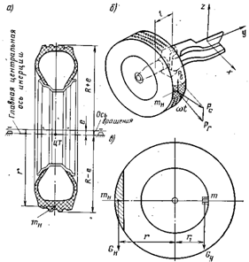 | Figure 1. Scheme of unbalanced wheels of the vehicle |
Practice shows that the dynamic imbalance usually increases with increasing width of the wheel. Wheel balanced dynamic way, is and statically balanced. This method of dynamic balancing of wheels car of the most common and preferred. Definition of imbalances and the selection of appropriate weights are made by means of special mechanical or Electromechanical pressure machines.Analyzing the above shows that the balancing of wheels of cars and trucks is the most important element in the part of ensuring the reliability and safety of operation in practice. To do this, at plants making cars, repair enterprises, fleets and in the paragraphs maintenance are widely used various in design, both domestic and foreign balancing machines. Such diversity requires considerable labour and material costs for their content and therefore the development of new, more effective methods of balancing of wheels of cars without the use of balancing equipment at the present time is an important task. With this in mind, the article describes a new unknown world practice of construction, established at the level of invention, the wheels of motor vehicles, allowing in an automatic mode in the process of their movement to balance the past, that, in the end, will increase the reliability of the propulsion parts of cars, as well as the safety of their movements in operating conditions.
2. The Aim of the Research
Considering the above, in Elets state University I.A. Bunin, conducted research on the topic «Dynamics, strength and reliability of transport, road construction and agricultural machines, as well as the industrial standard and non-standard equipment in relation to Black-earth region of the Russian Federation and one of its sections is the scientific direction is connected with the development of advanced technical solutions that ensure the balancing of wheels of cars without the use of pressure machines and the dismantling of the past with the vehicles. Analysis of scientific-research reports in the areas of technology, literary sources, domestic and foreign patents allowed to develop a more simple and effective method of automatic balancing of wheels due to the location in their закраинах the rolling elements. Two of these devices recognized as inventions (RU2284921, RU2346827). Therefore, the aim of the work is to conduct analytical studies on the kinematic and geometric parameters of adaptive device providing the balancing of wheels of cars in motion without their dismantling.
3. Methods
Consider a rotating disc moving on a horizontal plane, which has a concentrated mass m0 causing the imbalance and freely moving body rolling own weight mj located in the disc. It is known that the balancing of the mass m0 will occur at a time when the masses of mj will occupy the position of тj/ located in the plane of the XX passing through the center of rotation of the disc and the centre of gravity of the unbalanced mass m0, or in the planes OX' (OX1') located to her under a certain angle, which determines the position of the dynamic counterweight and depends on the difference of mass m0 and mj. At change of frequency of rotation of a ω, such a disc, the angle will be adjusted in the automatic mode, which would provide reliable balancing of rotating disc with its translational motion.Make an equation of motion of the disk, using the calculated scheme (Fig. 2), with the following symbols: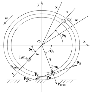 | Figure 2. The calculation scheme of the disk |
θj - angular deviation j the rolling elements from the axis ОХ, radians;rj - the radius of the provisions of the rolling elements to the center of the disk rotation, m;mj - unladen mass of the rolling elements, kg;ω - the angular rotation speed of a disk, sec-1;m0 - curb weight imbalance, kg;r0 - the radius of the provisions of imbalance to the center of the disk rotation, m;θ0 - angular deviation of the imbalance of the OX axis, radians;J0 - the moment of inertia of the disc with the account of the imbalance m0, kg∙ sec2∙m;тк - total weight of the disc and the guides with the bodies of rolling, kg;Jk - moment of inertia of the disc and the guides with the bodies of rolling, kg∙ sec2∙m;РД - the driving force applied to the rolling, N;РИ - inertial resistance force, N;PG -resistance force of its own weight of the rolling elements, N;РВС - the power of the adverse resistance movement of the rolling elements, N;Рциmj - the centrifugal force of inertia, N;Рциm0 - the centrifugal force caused by an imbalance of wheels, N.Consider the uniform movement of the disc, considering that he rolls over on the firm and smooth horizontal surface. Going to the field of complex numbers, and given that the ratio is of the form z = x + iy, let us write down the equation of the kinetic energy of the system without taking into consideration the the rolling elements in the form of: | (1) |
At the same time, considering that the rolling elements in the quantity of N pieces are material points, take for the generalized coordinates of the components of the vector of velocity of its rotation z and angles for each of them θj, j=0…N. The result of the expression of kinetic T and potential П energies will be written in the form of. | (2) |
 | (3) |
Using expressions (1) and (3), we write the Lagrange equations of the 2nd kind for the system without the rolling elements: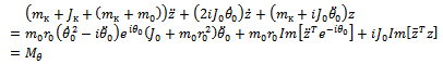 | (4) |
where Mθ - external torque applied to the drive.For the study of stationary regimes assume that the disk is rotating with a constant angular velocity θ˙0 = ω and then you can write down the expression in the new form of the vector variable w = ze−iωt.Consider the neutral mode of rotation of the disk, which is characterized by the initial stage of its forward movement in this by assuming that for some values of a permanent w = w* = const and then the equation (4) can be written in the following form: | (5) |
Transforming the equation (5), as a result we obtain the ratio of the dependence of the mass of the imbalance of the mass of the disk in the absence of pressure the rolling elements: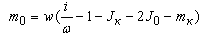 | (6) |
Let us now consider the neutral modes of motion of the disk, where it will be located the body of rolling, in which the axial line of the center of rotation and angles, describing the situation of pressure the rolling elements, retain permanent position in the rotating coordinate system. To find the dependence of the mass of the rolling elements and the number of them from the mass of imbalance in the system (6) let us introduce the following assumptions 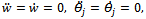
 As a result, you can write the following equation:
 | (7) |
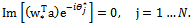
Believing that w* = 0, then from the first equation of system (7), we obtain the following relation: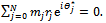 | (8) |
This dependence means that the center of gravity of the system formed by balancing the bodies of the rolling elements and imbalance, lies at the point O, characterizing the center of rotation of the disc. Proceeding from this, assume that all of the rolling elements have the same weight mj and are located at the same distance rj from the center of rotation of the disc. In this case, you can define the number of the rolling elements necessary to balance out the imbalance of the disc by the condition: m0r0 ≤ 2mjrj.On the basis of the above can be considered as that presented above equation, recorded for a rotating disk, can be used in studying the phenomenon of imbalance, for example, and for the wheels of the car. It is known that according to GOST 4754-97[6] values of the masses of the wheel weights mounted on each side of the vehicle wheels shall not exceed 60 g for radial tires with the rim diameter 13” and 80 g for diagonal tyres with the same diameter of the rim. When such restrictions in case of a natural semi-axis misalignment at each wheel is set, the axis of symmetry and the residual beating him on the suspension will also be limited. The state standard requires the implementation of these constraints in dynamics.It is known[7] that imbalances wheel Assembly in their respective planes of correction are expressed complex numbers: | (9) |
where,  - disbalance mass and the mass of the rolling elements in the plane OXY;
 - the angle that defines the location of the disbalance mass in the plane OXY;
  - the angle that defines the position of the rolling elements in the plane OXY.By entering the angle of rotation ϴ1 imbalance on the rolling elements, the current imbalance wheels, depending on the angle of ϴ1 with known values can be defined according to the formula:
 where
where  the values of disbalance mass and the mass of the rolling elements depending on the angle of ϴ1 in the plane OXY;
 - angles, showing the location of disbalance mass and location of the rolling elements on the plane OXY.Further, considering the known values
  , create a function on the basis of the conditions of optimization of the mutual position of the rolling elements on the imbalance. For this function requires two conditions:
 ;
; .Hence it follows that
  . To search for the maximum of the function f(ϴ1) have been investigated the changes in the different angles ϴ1 in limits from zero up to 3600.
 | Figure 3. The graph of f(ϴ1) |
Analyzing the graph shows, that to avoid imbalance wheels need to comply with the condition when the body rolling on the latter will be located in relation to each other at an angle ϴ1=1800. When you change the peripheral speed of rotation of the disc, the angle of ϴ1 will automatically be adjusted, which would provide a reliable dynamic balancing of the latter.Given this feature, consider the technical solution (RU2346827) allowing to effectively increase the operational reliability of rolling stock, using automatic balancing of wheels of cars and trucks, trailers and semi-trailers to them without dismantling them with proper maintenance.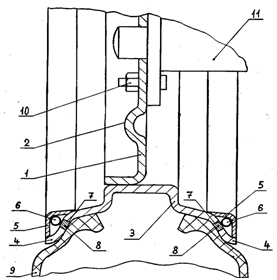 | Figure 4. Wheel cross section |
As figure 4 shows the part of the wheel of a passenger car in the section on Fig.5 dynamically unbalanced and dynamically balanced impeller and 6 dynamic loading scheme wheel imbalance and mobile balance the masses. A wheel of a passenger car (Fig.4) consists of disk 1 with the projections for decorative hood 2 and rim 3 with on-Board edges coated 4. For airborne rim 4 on both sides of the rim 3 rigidly attached rings 5 and in the space between the edges coated 4 and 5 rings mobile are the rolling elements 6 spherical form. In each of the rim performed by one cone hole 7 and there are plugs 8. On the rim of the 3 wheel mounted tire 9, and disk 1 with the help of bolts 10 is mounted on the hub 11 wheel.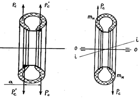 | Figure 5. Dynamically unbalanced and dynamically balanced wheel |
Working wheel of a passenger car in the following way. At the initial moment of time, when the car is at rest, the body of rolling 6 spherical form, which can be a few pieces on each side of the rim are at the bottom of the wheel as it is, for example, illustrated in figure 4, mobilize himself there, under the influence of its own weight. It is known, that due to the errors of manufacturing of the parts of the wheels and the other reason for the rotation of the wheel is constantly changing position of the unbalanced mass mn located, for example, as it is shown in Fig.6. The unbalanced mass of the wheel in this case are given to the two masses mН lying in the centre of the plane. At the initial moment of rotation of the wheels of the rolling elements are located at the bottom of the wheel as it is, for example, illustrated in figure 4, mobilize himself there, under the influence of its own weight. It is known, that due to the errors of manufacturing of the parts of the wheels and the other reason for the rotation of the wheel is constantly changing position of the unbalanced mass mn located, for example, as it is shown in Fig.6. The unbalanced mass of the wheel in this case are given to the two masses mН lying in the centre of the plane. When the wheel rotates in the locations of the centres of gravity of the unbalanced mass arise centrifugal force in the Рс. These forces actions in opposite directions create a couple of forces, time which is equal to М=Рс·а. Such a moment and characterizes the magnitude of the imbalance. It is clear that to achieve a dynamic equilibrium at закраинах rim establish balancing weights, creating the centrifugal forces of the Рс (centrifugal weights on the figure 5 shows the triangles black, attached to on-Board rims). Such an operation is labour-intensive and for its simplification in the proposed technical solution used automatic way to redress the imbalance. So (see figure 6), where a disc wheel is divided into two parts right and left, when driving a passenger car of its wheel rotates in a clockwise direction B and body rolling 6 (these are shown as one spherical shape of the body-ball), for example, located to the left (see figure 6), as the capacity of the district speed Vк have the angular velocity  of a somewhat smaller due to the fact that in the past the forces of inertia Ри, the force of its own weight Pg and the powers of the harmful resistance Рвс. At the same time on the rolling elements spherical form 6 acts and the driving force Рд, which is aimed in the direction of rotation of the wheels of the vehicle on the arrow B and results from the forces of friction between the bodies of the rolling 6 and the inner surface of the ring 5.Suppose that at the wheel there is an imbalance ∆1, which is manifested from the unbalanced mass m1 and then centrifugal inertial force Рци m1, it will be determined depending on Рци m1= m1
 , where m1·ρ = ∆1. At the same time on the rolling elements spherical form 6 will also be the centrifugal inertial force Рци mш=mш
 , where mш·
 =∆2, and ∆2 is a dynamic counterweight. Above it was noted that the balancing of the masses m1 will happen then, when the mass mш would be in the position situated in the median plane of the wheel XX and the centre of gravity of the unbalanced mass m1, or in planes ОХ’(OX1’) located to her at an angle
  , which determines the position of the dynamic counterweight ∆2 and depends on the difference of the masses m1 and mш. Such process of the provisions of the masses mш spherical bodies rolling 6 being mobile detects the orientation of the dynamic counterweight ∆2. When you change the peripheral speed Vк of rotation of a wheel of a passenger car, the angle of ά in the automatic mode for both sides of the disc 1 wheel in the automatic mode will be adjusted, which would provide a reliable dynamic balancing of wheels of the vehicle in an automatic mode, moving with great speed.Consider the example of a simplified engineering calculation of necessary quantity of the rolling elements spherical shape and weight installed on a wheel, for example, passenger car GAZ-3102 «Volga», which has the following characteristics - its own weight of the tire 13 kg, the designation of tire 205/70R14, the outer diameter of the tire 652 mm. Domestic and foreign experience shows[3], the average tire imbalance car proportional to the product of their own weight to the free radius
  . To determine the numerical values of the imbalance in our example, we use the schedule presented in the work[3], obtained in the result of the survey 65000 tires, both domestic and foreign production, and then the average unbalance value will be determined:
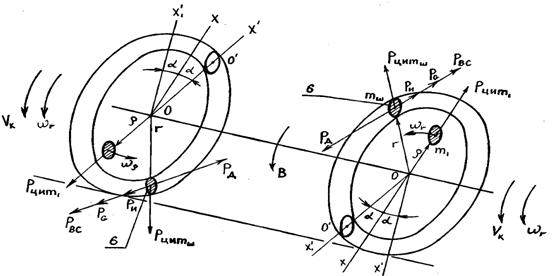 | Figure 6. Calculation scheme |
 We now define the imbalance
  , the vector of which is applied at the point of pairing the bus and drive wheels on the outer side of his rim given that the radius of the point
  is 19,2 cm. Using the equation of statics
  and presented
  and
and  in the form of vectors of forces compute
 .We calculate the weight of the cargo rolling-stock (spherical bodies of rolling), which is active in the drive wheels, as it is described in the patent RU2346827. Using the above-mentioned schedule, set the imbalance
  to the appropriate value
  , and then the full weight of a spherical the rolling elements will be determined:
 Then the total number of the rolling elements spherical shape at one закраине wheel will be:
  As a material of the ring, in which are located the body of rolling spherical in shape, can be recommended carbon quality Steel 08кп or 15кп according to GOST 1050-74 good working abrasion, that is, from the rim and wheel rim class 2 used in the manufacture of wheels for passenger cars.
4. Results
Analyzing the above, the following conclusions can be made. So the analysis of currently existing methods and techniques of dynamic and static balancing of wheels of cars in the operating conditions do not meet modern requirements of traffic safety vehicles and therefore the development of the inventions RU2284921, RU2346827 adaptive devices to operate the motor vehicles without dismantling their wheels of the latter is a very relevant. Conducted analytical studies have shown that the elimination of imbalance of the wheels of the vehicle takes place under the conditions, when the rolling elements relative to the last will be located in relation to each other at an angle α =1800. At the same time represented by a numerical example, made with the use of methods of allowing in practice to obtain preliminary data on the determination of the number of the rolling elements necessary to exclude the imbalance wheels, showed that, for example, for the wheels of a car GAZ-3102 «Volga» number of the rolling elements located in закраине wheels should be equal to the order of 5 shares of total own weight 0.30 kg.
5. Discussion and Conclusions
The results of the study recommended a transport and industrial enterprises, exploiting and manufacturing of the motor vehicles, as in our country, and abroad to study, the proposed technical solution and possible in the future its implementation in practice. To calculate the weight of the rolling elements spherical form and the number of them installed in the different design of the wheels of trucks and passenger cars as well as buses, wheeled tractors and car and tractor trailers and semi-trailers designed a computer program using a language Delphi, which has been tested on the example shown above. It should also be noted, that the calculated parameters are determined according to this methodology, are indicative and may not be recommended for short-term use, and therefore, for the final evaluation of the effectiveness of the use of the proposed technical solution it is necessary to carry out extensive tests on the performance and efficiency.
References
| [1] | Autotractor wheels: Spravochnik / Under the editorship I.V. Balabin.- M.: Machinery, 1995.-272 p. |
| [2] | Artobolevsky I.I. Theory of mechanisms and machines. M.: Nauka, 1985.-640 p. |
| [3] | Knoroz V.I., Klennikov E.V. Tires and wheels. M.: Machinery, 1985.-184 p. |
| [4] | A summary of the automobile reference book. - 10-e Izd., pererab. I dop. - M.: Transport, 1983.-220 p. |
| [5] | Levitsky N.I. Theory of mechanisms and machines. - M.: Science, the Main editorial office of physico-mathematical literature, 1979. – 576 p. |
| [6] | Journal of applied mechanics. Textbook for higher educational institutions. Under the. Ed. V.M. Osezky. Izd. 2nd, revised. and dop. M.: Machinery, 1987.-488p. |
| [7] | The work of the tire. Under ed. V.I. Knoroz. M.: Transport,1986.-238p. |
| [8] | Slivinsky E.V., Zaitsev A.A., Novoselov V.V. The wheel of a car. Patent RU2284921. dated 10.19.2006. Bul.№28. |
| [9] | Smirnov G.A. Theory of the motion of wheel machines. A textbook for the students of the railway special schools.-2-e Izd., added and revised.-M.: Machinery, 1990.-352 p. |
| [10] | Theory and design of the car. Textbook for motor colleges/ V.A. Illarionov, etc. - 2-e Izd., pererab. I dop. - M.: Machinery , 1985.- 368p. |
| [11] | Technical exploitation of cars: Uchebnik dlya vuzov / pod red. G.V. Kramarenko. - 2-e Izd., added. and dop. - M.: Transport, 1983. – 488p. |
| [12] | Feodosiev V.I. Resistance of materials. M., SHKOLA, 1980. |
| [13] | US 3006690 A, 31.10.1961. |
| [14] | US 3913980 A, 21.10. 1975. |
| [15] | RU 206723 C1, 27.10.1995. |
| [16] | Melnikov A.E. Automatic balancing of flexible rotors. Author's abstract of the dissertation on competition of a scientific degree of the candidate of physical and mathematical Sciences. Saint-Petersburg, 2011. |
| [17] | Bykov V.G., Melnikov A.E. A mathematical model of the flexible rotor on the basis of generalized Lagrangian coordinates. // Vestnik of St. Petersburg state University, S.1, vol. 4, 2010, p. 110-118 |
| [18] | Bykov V.G., Melnikov A.E. Automatic balancing of the disk in the floppy massive shaft. // Vestnik of St. Petersburg state University, S.1, vol. 1, 2011, p. 116-126. |
| [19] | Slivinsky E.V., Zaitsev A.A. Automatic balancing of wheels of cars in their movement «Automobile industry». Monthly scientific-popular, production-and-technical magazine. №6. M: machine-building, 2008.-16p. |
| [20] | Improvement of the design of devices and units of automotive and tractor train Monograph/ Slivinsky E.V., Zaitsev A.A. - Elets: ElSU them. I.A. Bunin, 2009.- 236p. |
 Abstract
 Reference
 Full-Text PDF
 Full-text HTML