-
Paper Information
- Previous Paper
- Paper Submission
-
Journal Information
- About This Journal
- Editorial Board
- Current Issue
- Archive
- Author Guidelines
- Contact Us
International Journal of Traffic and Transportation Engineering
p-ISSN: 2325-0062 e-ISSN: 2325-0070
2012; 1(4): 77-83
doi: 10.5923/j.ijtte.20120104.04
The Development of the Parking Brake for Freight and Passenger Cars with Control from the Driver's Cab
E. V. Slivinskiy, E. A. Suzdalskaya, T. E. Mitina
Mechanical Technological Faculty, Elets State University I.A. Bunin, Elets, 399770, Russia
Correspondence to: E. V. Slivinskiy, Mechanical Technological Faculty, Elets State University I.A. Bunin, Elets, 399770, Russia.
| Email: |  |
Copyright © 2012 Scientific & Academic Publishing. All Rights Reserved.
In this article considers the issues on the development of perspective design of the Parking brake at the level of inventions for railway rolling stock. The offered design allows in an automatic mode in case of exhaustion of a brake to exclude possibility of self-movement of a railway rolling stock. As a result of the carried-out researches the design procedure of parameters of not direct-action pneumatic brake on an example of the freight car is developed by loading capacity of 60 t. The analysis of the conducted studies allowed us to substantiate the constructive characteristics of the proposed technical solution, in relation to other rail vehicles. The results of the studies are recommended design, scientific-research and engineering structures for possible use them in practice.
Keywords: Brake Pad, Additional Cylinder, Auxiliary Cylinder, Brake Master Cylinder, Rod, Piston, Spare Tank, Valve
Cite this paper: E. V. Slivinskiy, E. A. Suzdalskaya, T. E. Mitina, "The Development of the Parking Brake for Freight and Passenger Cars with Control from the Driver's Cab", International Journal of Traffic and Transportation Engineering, Vol. 1 No. 4, 2012, pp. 77-83. doi: 10.5923/j.ijtte.20120104.04.
1. Introduction
- It is known[1, 2, 7, 8] that the most important part of the technical facilities of railway transport is rolling stock, which is designed for the transport of goods and passengers by rail. One of the most important criteria for the evaluation of the rolling stock operation is traffic safety. Therefore, all of the organizational-technical actions on the railway transport are directed on maintenance of the constant working order all railway structures, paths, rolling stock, equipment and mechanisms, SCBD (Signaling,Centralization and Blocking Devices) and connection by means of their examinations, preventive maintenance, and, of course, their constant modernization at the expense of introduction of achievements of science and technology. Modern passenger and cargo carload Park includes a variety of types and designs of this kind of rolling stock, which is conditioned by the necessity to satisfy the various requirements imposed on him. All types and kinds of the rolling stock should have a high slash ability to provide comfortable conditions for passengers, have the flexibility to have a high coefficient of use, etc. These factors determine the number of requirements to the structure of the cars, which are in equipping them automatically applicable brakes, using automatic coupling devices, improvement and unification of the chassis, in the application of modern systems of heating, air-conditioning, sanitary-technical equipment, electrical equipment, ventilation, etc.At the present time in the construction of cars have found wide application of pneumatic brake devices. Such devices are called indirectly acting pneumatic brake, because when you break the train or brake lines, as well as at the opening of the crane emergency braking is automatically come into effect. Thanks to a more rapid and efficient action, auto brakes increase safety of traffic and allow to significantly increase the speed of movement of trains. However, during prolonged braking, or Parking of train, or single cars in detached position from the engine the air pressure in the brake cylinders and spare tanks gradually decreases, due to available leaks, which leads to depletion of the brakes. This is a significant disadvantage of indirectly acting automatic brakes[1, 6].Analysis of existing brake systems of domestic and foreign rolling stock[9, 16] shows, that for today there are no technical means to enable in the case of leakage of compressed air from the spare tank locomotives or wagons and the absence of brake shoes, laid on the tracks under their wheels, exclude its independent movement as in these ways, and the routes to points of the season.
2. Objectives
- For a number of years (in the period of 2008-2011 ys.) in the Department of Applied Mechanics and Engineering Graphics of Bunin Elets State University by the order of the Elets Railway Department and the Administration of the South-Eastern Railway, a branch of OJSC «Russian Railways», carried out research aimed at improving the efficiency and safety of a rolling stock and its modernization. One of the sections of this scientific-research work is a theme connected with the development of technical means, excluding an independent movement of rolling stock, owned as on the trunk and station tracks, as on the ways of their settling.The aim of work is to conduct a patent search, preparation of application materials for inventions on the design and synthesis, and the definition of some structural parameters of the Parking brake for freight and passenger cars.Taking this into account and analyzing numerous bibliographic sources and domestic and foreign patents, we developed a number of advanced technical solutions aimed at the exclusion of independent motion of railway rolling stock in the case of depletion of the brakes, recognized inventions №№ 2255872, 2374111, 2391240, 2397898, 2397900, 2397899, 2391238, 2402443, 2399526, 2399525, 2412074, 2412843, 2412844, positive solutions FIIP (Federal Institute of industrial property) from 22.05.12, on the patents of the Russian Federation for inventions to applications No. 2011118300/11, 2011118298/11, 2011118302/11, 2011118308/11.
3. Methods
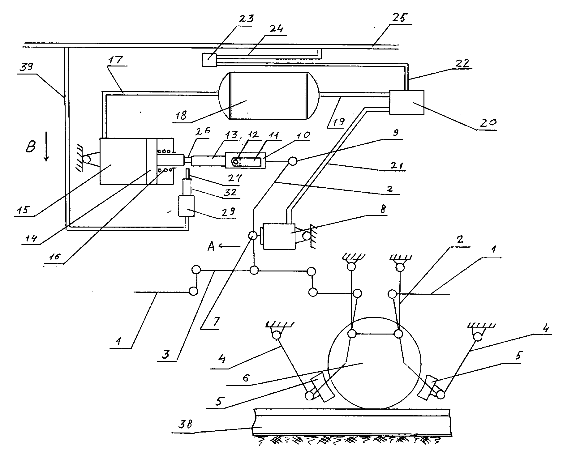 | Figure 1. The principle of the brakes |
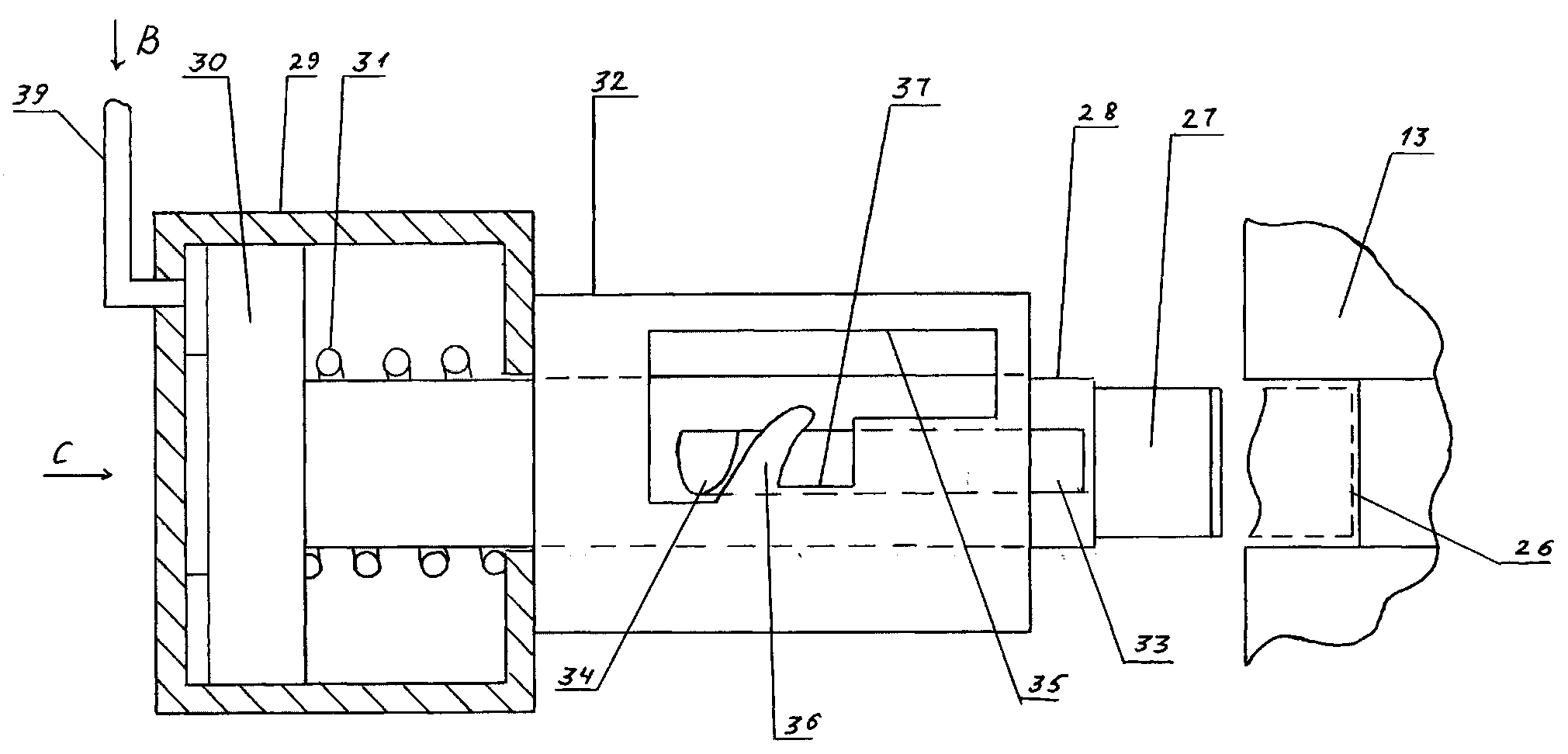 | Figure 2. Fortified node of the fixing device |
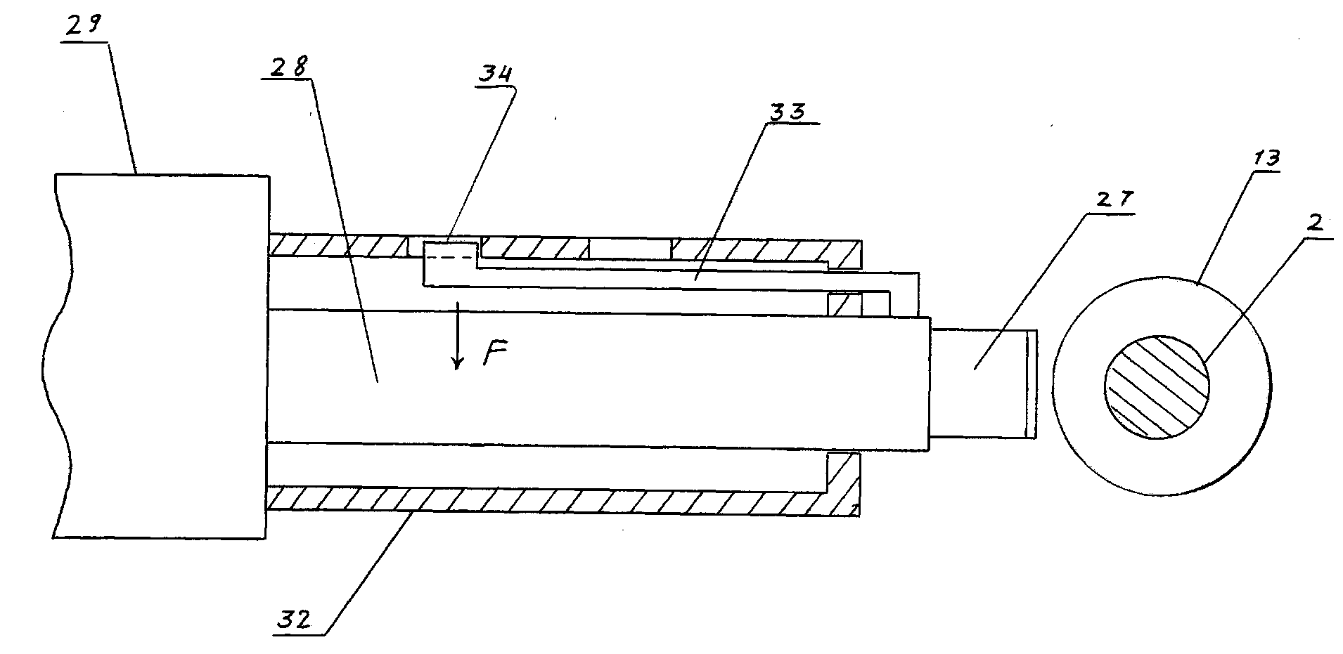
 | Figure 3. Part of its cross-section vertical plane |
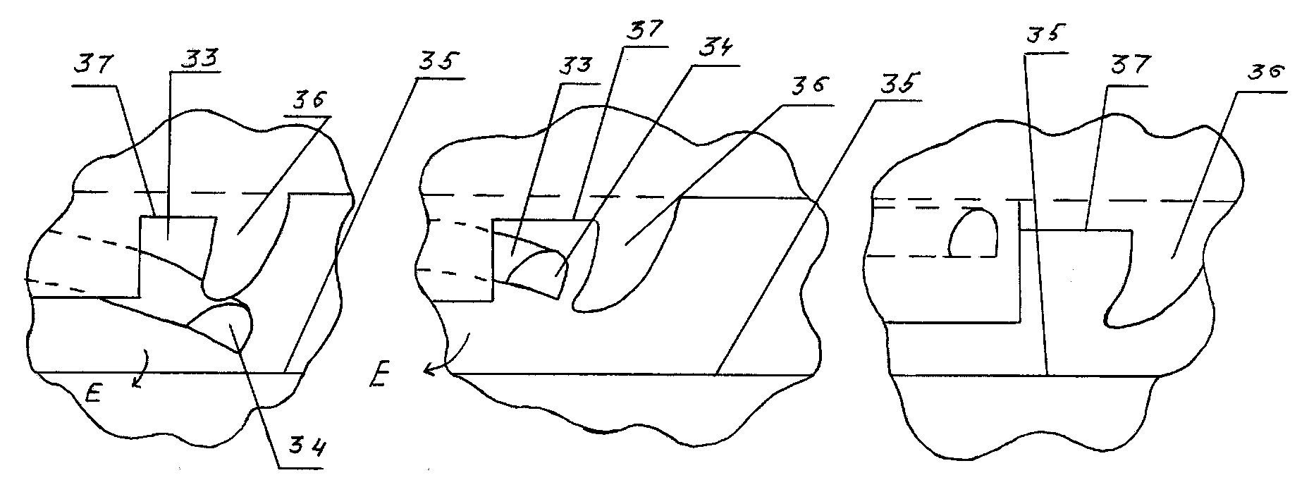
 | Figure 4. Points triggering of the fixing device |
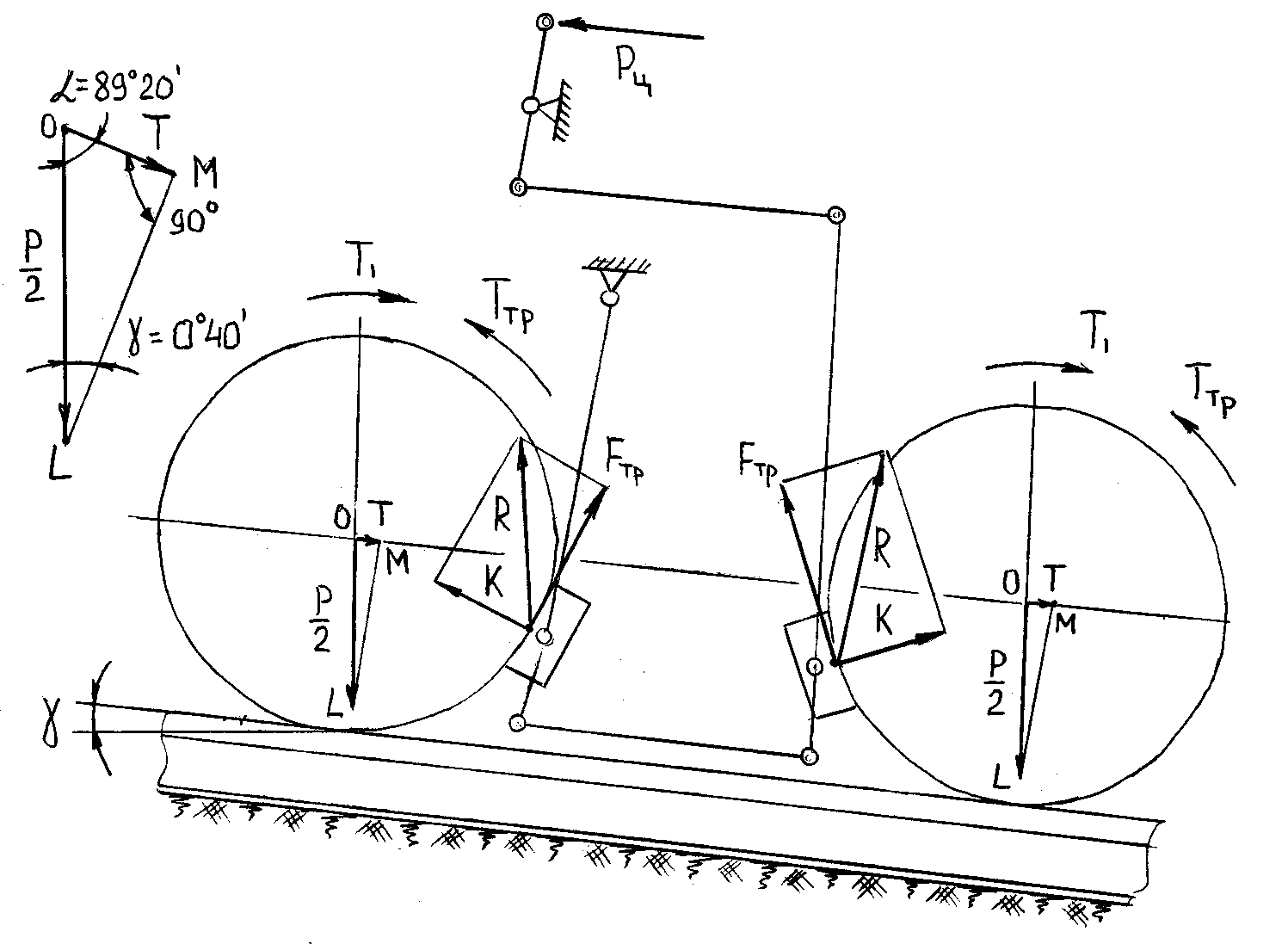 | Figure 5. Settlement scheme of the device |
 where: fsl coefficient of friction of pig-iron in steel equal to 0.18 in[2].Consider, that under such pressure of the compressed air in the brake cylinder with a diameter of 12" (304.8 mm) with the total area of the piston S = 730 cm2 his rod develop the effort Py = pS = 3,5∙730 = 2,5 t. Then, knowing the power of pressing ∑K all four axis of wheel pairs of carriages gondola ∑K = 9∙4 = 36 t, we can define the gear ratio of brake slack Adjuster.
 .Suppose that the pressure of the compressed air through a variety of leaks fell to 0.15 MPa, then Py = 1.5 ∙ 730 = 1.1 tons and ∑K = Py ∙U = 1.1∙14.4 = 15.8 t, therefore, in this case the force clicking on one wheel K is K = 15.8 / 8 = 1.9 tons, and the friction force is equal to Ffr = K∙ fск = 1.9∙0.18 = 0.35 t.If the gondola is located on the slope of visitors ‰, as it is described above, it is clear that independent movement its the same as and at a pressure of compressed air 0.35 MPa possible. Now, suppose that for the first case, when p = 0.35 MPa slope of 10 ‰ that is, the angle of γ = 0º 40’ (Figure 5) and then to the wheel will be applied force T, defined from a rectangular triangle ∆LOM as:
 Define now the moment T1 on the wheel, created by this power:
 (where dk wheel diameter, is equal to 900 mm)The moment of friction forces Tfr generated by friction force Ffr will be equal to
  = 0.36 t•m. It is seen that the Tfr > T1 therefore, gondola can't get an independent movement on the slope at a pressure of compressed air in the brake cylinder 0.35 MPa.To perform such calculations now at a pressure of compressed air 0.15 MPa at the same grade 10 ‰. Then, T1 = 0.16 t•m, and the Tfr = 0.35•0.45 = 0.16 t•m. This shows that T1 = Tfr and the subsequent reduction of pressure can lead to independent movement of the car.It is known[4] that screw springs of compression characterized by average diameter D, usually loaded at the ends, with current load is reduced to the forces P directed along the axis of symmetry of the spring and the pairs of points operating in face planes, perpendicular to the z axis.Using the method of cross-sections, suppose (Figure6) that in the favorites section A loaded spring specified loads of any internal components of efforts such as N - normal, Q-cutting in two planes and M - bending and twisting moments.
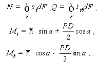 Usually in the practice of force N and Q are of secondary importance in comparison with the twisting and bending moment Мtu Мbu so they take as the estimated parameters in the study of stressed state of springs installed in the option cylinder brake. It is known[4] that in the process of deformation of the spring compression turns her move relative to each other steadily, and this testifies to the absence of a relative rotation of the cross sections of the spring. And therefore, given that the movement of spring are small compared with their respective sizes, as well as its ends are not turning you can use the following dependencies, allowing to calculate the axial displacement of the spring λ0 and moments
  acting in the end planes, perpendicular to the z-axis by the following formulae:
 where E is the modulus of elasticity of the material;μ - Poisson ratio;d - diameter of bar springs.
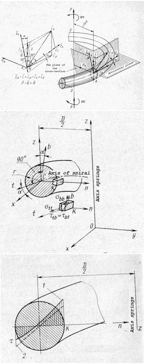 | Figure 6. Settlement scheme of a spring |
 Earlier it was noted that the loading of the cylindrical spring at the ends of the axial forces and a couple of moments, it turns working simultaneously on torsion, bending and stretching-compression, and with such an approach the normal and tangential stresses in the cross sections of turns can be determined by the known dependencies:
 where, β – coefficient that depends on the form of the cross section of a coil.But as the coils of cylinder springs usually have a large curvature, and that significantly influence on the law of distribution of internal forces in the cross sections of turns, which leads to a significant increase of stress. Therefore, the calculation of stresses arising in the domestic fiber turns in dangerous points (point K on the figure 6) are recommended to be defined by the formulas obtained using methods of the theory of elasticity N.A.. Chernyshev[4], which have the form:
 where, kbp, ktp , kp – ratios, depending on the angle of the coil α and the spring C the Poisson's ratio of μ = 0,3.On figure 6 as a representative example of the power of loading coil screw springs of compression of a solid line shows the graph of the distribution of tangential stresses on the diameter of the cross-section of its spire, built with the use of formulas obtained by the method of the theory of elasticity, and the dashed line shows the stresses arising in the direct beam of circular cross-section in its pure torsion. It is seen that the numerical values of tangential stresses in the first case, more than in the second, and therefore the definition of their using these formulas is the most important.The calculations showed that the motion for the exclusion of the car in case of depletion of brake spring compression 16 additional cylinder 15 (Figure 1) should develop the force of the order of 1.32 tons (coefficient of stock takes 1,2). This spring should have the following characteristics: Dout = 160 mm; Dav = 138 mm; diameter of bar 22 mm, step t = 44 mm, the height of the Hfr = 407 mm, material steel 60С2 according to standard 2590-51. The working effort this spring is 1.4 tons. For the spring calculate the numerical values of normal and tangential stresses arising in the this spring on the above formulae:
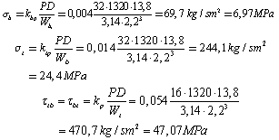 where, kbp, ktp, kp when C = D/d = 138/22 ≈ 6 and α = 150 respectively selected in table 4.5[4] is equal 0,002, 0,014 and 0,054.The results show that the condition of the strength is performed for the material steel 60С2 according to the standard 2590-76, from which is made plain spring and has a tensile strength of σВ = 6760 kg/cm2 = 676 MPa.At the same time, analyzing the design of the brake and his work can be seen that the most crucial part is the corner of the form of elastic element 33 with Cam 34 (see figure 4), the essence of which is a flat spring, working with small movements in the linear or angular displacement of the spring determine the methods of resistance of materials. Usually in the design of such springs decide not direct problem, which we know its geometry and the desired values are displacements and stresses, and the opposite associated with the preliminary selection of material and in accordance with the terms of their work shall appoint the allowable stress. In the end, they calculate the strength and stiffness of the definition of the geometrical characteristics of the springs. Let us consider a numerical example the design of flats, duplexes spring, which is the elastic element 33 angular form with Cam 34 (see Figure4). Take as the working load acting on Cam spring will take P = 200 N, at that, which should be moving Δl = 20 mm. As a material accept steel 60С2А with modulus E = 2•105 MPa and with a limit of fluidity σТ = 1400 MPa. In the responsibilities of the parts working in the brake system of railway rolling stock choose factor of nT = 2.0, and then the permissible bending stresses will be:
 Let us ask ourselves the ratio l/h = 40, where the numerator spring length of 160 mm, and in the denominator of the thickness of 4 mm and then the width of the spring b will be determined by the formula[3]:
 Ultimately accept the width of the spring equal 14.0 mm.Define now the normal stresses arising in the spring when the load is her effort 200 N, while constructively thickness of spring will increase up to 5 mm, depending on:
 Condition strength performed.
4. Results
- The carried-out researches allowed to develop a perspective design of not direct-action pneumatic brake for a railway rolling stock which in an automatic mode allows to carry out self-retardation of the last and to exclude thereby the emergencies connected with self-movement of locomotives and cars. Such design of a pneumatic brake has world novelty and is protected by the patent RU2397900. The carried-out analytical researches of such design allowed to calculate the geometrical characteristics of its element base allowing at pressure decrease of compressed air in the spare tank less than 0,15 MPa, at the expense of existence of the heat-sink device executed in the form of a screw cylindrical spring of compression, to create necessary pressure force on brake shoes about 13000 N and to exclude thereby a pro-collar of wheel pairs of rather rail way with a bias less than 10 ‰. As a result of the carried-out calculations numerical values of the tension arising in rounds of springs at their compression by nominal pressure in brake system of equal 0,65 MPa which don't exceed allowed values for this chosen material of 700 MPa are also received. The developed settlement schemes and techniques of carrying out analytical researches of power loading of constructional elements of the device are recommended for practical application at design and designing of a railway rolling stock of various type and appointment.
5. Discussion and Conclusions
- In conclusion it should be noted that different types of freight and passenger cars may be equipped with the above-mentioned devices and with consideration of their mass and structural characteristics were calculated, using the method presented above, as well as the developed computer program in Delphi, and have the design parameters of the system of self, which correspond to their scope and purpose. The results of the study submitted to the heads of Administration of the South-Eastern Railway, a branch of OJSC «Russian Railways» in the form of an Express statement on the part of the above research, and are also recommended to use the relevant research institutes, specialized design bureaus and industrial enterprises, designs and manufacturing passenger and freight rolling stock, both in our country and abroad.
 Abstract
 Reference
 Full-Text PDF
 Full-Text HTML