International Journal of Traffic and Transportation Engineering

p-ISSN: 2325-0062    e-ISSN: 2325-0070

2012;  1(4): 60-66

doi: 10.5923/j.ijtte.20120104.02

Development of Timing of High Efficiency for Diesel Engine

L. A. Savin, O. A. Pivovarov, S. J. Radin, E. V. Slivinskiy

Mechanical Technological Faculty, Elets State University I.A. Bunin, Elets, 399770, Russia

Correspondence to: E. V. Slivinskiy, Mechanical Technological Faculty, Elets State University I.A. Bunin, Elets, 399770, Russia.

Email:

Copyright © 2012 Scientific & Academic Publishing. All Rights Reserved.

Abstract

In this article questions on development and calculation of a perspective design of the gas-distributing mechanism created at level of the invention, ICE of locomotives are considered. The technique of design of the main geometrical and thermodynamic features on an example of one of the presented technical solutions is offered. Results of researches are recommended to design, research and machine-building structures for their possible use in practice.

Keywords: Gas-Distributing Mechanism, ICE, Thermodynamic

Cite this paper: L. A. Savin, O. A. Pivovarov, S. J. Radin, E. V. Slivinskiy, "Development of Timing of High Efficiency for Diesel Engine", International Journal of Traffic and Transportation Engineering, Vol. 1 No. 4, 2012, pp. 60-66. doi: 10.5923/j.ijtte.20120104.02.

1. Introduction

It is known[1-10] that the Diesel generator is an essential part of the transport and power engineering. Growing demand for internal combustion engines (ICE) for the locomotive, shipbuilding, oil and gas industry, low energy, as well as further the future development of these sectors brings the task of creating and organizing the production of new types of diesel engines for them as a priority, subject to a product produced by the progressive Techno-economic performance and higher aggregate output. Increased efficiency, and reduce the aggregate power metal while maintaining the modern diesel engines, especially when the desired increase in reliability and durability require an extended set of research projects to ensure the strength of all members of the product, parts and components for full coverage of the possible factors and their loading conditions [1-3]. Reliable operation of diesel at the present stage of development of the engine-building is largely dependent on the reliability of each of the members of the design elements. The probability of damage to be particularly low at a multiplicity of similar elements in the design. We also know [7-9]that the exhaust and intake valves arerespon-governmental mechanism for timing details. They are in the immediate vicinity of the flow of the workflow inside the cylinder. Lack of reliability of the initial valve operation can result in damage to the working cylinder, and other critical parts with the failure of the engine and power plant, respectively, of the vehicle in many cases with threat to its security, and always with high material costs of recovery. Among the details of cylinder-piston group (CPG) is gas distribution valves operate in the harshest conditions on the degree of impact: high uneven heating to temperatures of active corrosion protection, mechanical wear out shock loads and vibrations resulting from a variety of stimulating factors. Given the above, it is clear that the existing structure of gas distribution mechanism (RM) is still far from finished. Therefore, research conducted in this field of technology are highly relevant.

2. Objectives

Considering the above-stated, in Bunin’s ELSU and OSTU, working out of practical recommendations about increase of reliability, technical and economic, technological and operational indicators is spent research on a theme «at operation and repair of a rolling stock and other equipment used on Yelets branch of the Southeast railway». According to the results of the analysis of bibliographic sources and patent University received a patent for an invention RU2397336, associated with the modernization of the camshaft four-stroke internal combustion engine and to some extent, excluding the above drawbacks. Thus, the purpose is to improve the design and improvement of performance of gas distribution mechanisms through application of the new ICE unknown world practice perforated valve, allowing to reduce the calorific, shock, and increase the capacity of the gas distribution mechanisms.

3. Methods

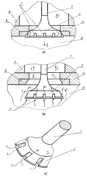
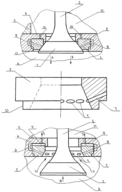
Diesel timing mechanism works as follows. Suppose that the valve is composed of a rod and the head 2, is the exhaust and is a member, for example, four-stroke diesel engine M750. When the working stroke of the piston in the cylinder of the diesel engine 6 (piston in Fig. Not shown) of the arrow A, 2 valve head firmly against the seat 3 (fig. 1), which prevents the penetration of gas into the cavity of the lid 5, which is known to associated with the zone in diesel exhaust. As soon as the stroke of the piston is stopped and the bottom dead center goes into forward motion in the opposite direction of arrow A, the valve opens (fig. 1.a) and the exhaust gases moving with the arrow pass through the orifice formed by the two valve head and a rod, seat 3 and 4 head cover 5. At the same time the exhaust gases pass through the slots 7 valve head 2 and is also streaming on the arrow C, go to the zone in the exhaust cover Figure 1 shows a valve timing mechanism of a diesel engine in a closed state, in (fig. 1.b) it is the same, but in the open state in (fig. 1.c) and part of it in the future. Diesel Engine Timing includes a valve consisting sisting of a rod and the head 2, which is located in the saddle 3, pressed into the bottom 4, the cover 5, the cylinder 6, at the head of the two valves are made grooves 7.
Figure 1. The valve timing mechanism
Consequently, the current volume of waste exhaust gases increase at the same time increases and decreases as the temperature-tension valve head 2 and 3 seats. As soon as the piston will be a certain distance of the lower dead point, the valve using a known mechanism for the drive is closed and the cylinder 6 is a process of compression of the combustible mixture. At the same time slots will be covered by a seven seat contact surfaces 3 and 2 and the valve head so that the gas mixture in the cylinder 6 can not be displaced into the cavity in the cover 5. In the future, these processes can be repeated several times. We carry out calculations to assess the effectiveness of the proposed technical solutions RU2397336 in the construction of a diesel engine exhaust valves 14D40 diesel locomotive M62.
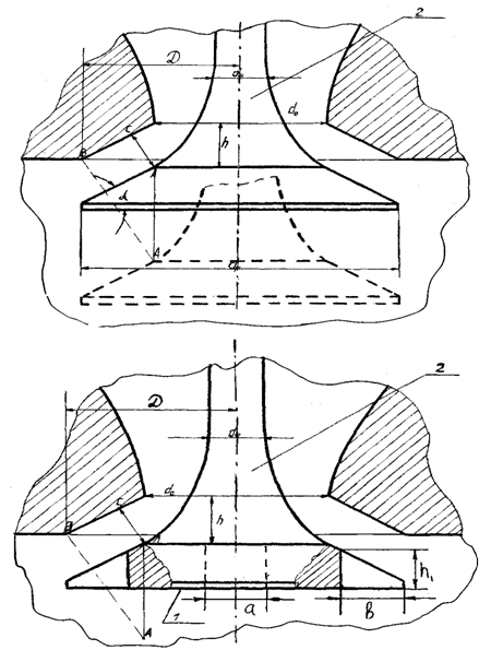
Figure 2. The design scheme
Consider a simplified timing diagram of the diesel engine, which represent the serial exhaust valve and an upgraded (fig. 2) by submitting them to a head in the form of a truncated cone, forming a small circle which is rigidly attached to the rod 2. According to the motor nameplate data 14D40[4], the diameter of the valve head dr = 0.088 m. The angle of the cone valve head internal diameter of the valve seat d0 = 0.075 m. The outer diameter of the valve seat D = 0.088 m. Valve stroke h is a function of crank angle, as well as constructive to accept that in a head made of the upgraded valve, n = 5 grooves, in which a = 0.025 m and b = 0.030 m. For a comparative assessment of the capacity of the serial and the proposed construction of valves using a known method for determining the cross-section of the valve provided in[1], which is based on the geometric method of calculating the valve gap and is as follows:
In the first section of the valve stroke, when the orifice is the correct form of the channel cross-section of which is the lateral surface of a truncated cone with generator equal to the length perpendicular to the speaker cone valve, assuming that the length between the valve and seat (see fig. 3, where the valve is outlined by a solid line). This section of the valve for mass and, accordingly, proposed by the formula:
(1)
where h - the valve on the first section, m, h1 = 0.1 m.
In the second portion of the valve stroke, when h2 = 0.3 m. Perpendicular from point A to the cone valve passes the cone section of the valve seat and lose the character of the right channel and then the orifice can be determined depending on the series as, respectively, for the proposed structures and the valve:
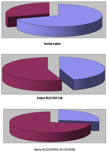
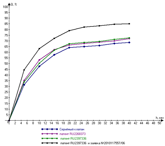
Figure 3. Graphs of the distribution capacity of the valve
(2)
(3)
In the third section of the valve stroke where, for example, h3 =0.045 m orifice in the gas path is minimal. Given the place occupied by the valve stem to determine the cross-section in this case can be determined from the dependence of as, respectively, for series and a promising valve:
(4)
where dsh - the diameter of the valve stem, dsh = 0.023m.
Substituting in these equations corresponding to the numerical values of the geometric characteristics of the serial and long-term valve area were determined flow area of valve slits for the two study designs, the area where you move the valve by 10 mm, respectively, were equal to 17.0 ·10-4 and 53.8·10-4 m2, while moving at 30,0·10-4 m2, 28.4·10-4 m2 and 65.9·10-4 m2 and a maximum displacement of 45.0·10-4 m2, respectively, were 39.4·10-4 m2 and 77.5·10-4 m2[8]. It is seen that the average rate for a prospective design in a 2.48 times higher than for the series.
By varying the geometric dimensions of the holes, grooves and channels, you-filled valves in the heads and the rod, on the basis of patents (RU2397336, RU2316655, RU 2433283), providing a reliable overlapping compression chamber and the engine exhaust manifold with respect to a diesel engine 14D40, set reasonable size perforated holes and phase diagrams (see fig. 3), which indicated their total area designated for the passage of exhaust gases in comparison to the entrance area, which is provided in the current commercial valve.
The calculation results show that with increasing flow section area of holes, grooves and channels of the rod, available in the future designs of valves, in comparison with the serial, its throughput ability of respectively 1.45 and 1.8 times higher than that of the serial. We believe that the process of heat exchange that takes place in the valve head, as serial and modernized stationary samples taken, and the head valve is a flat wall. In this case, used the differential equation of thermal conductivity of the form:
(5)
- the Laplace operator .
Assuming that the internal heat sources are not available , then equation can be written in final form:
(6)
To determine the amount of heat passing through the unit to the wall surface per unit time in the direction of the x-axis, usually used by law Fourier Given that , after substituting the values in the expression of Fourier's law we obtain the following relationship:
(7)
Integrating expression in the range from x = 0 to any of the current X coordinate in the interval from tc1 to t obtain an expression characterizing the temperature field:
(8)
From this equation it follows that the temperature of the wall thickness varies according to the law and the nonlinear nature of the temperature curve is determined by the sign and the dimensionless coefficient b, whose value can be determined by the formula:
(9)
where - the temperature of the valve is installed at its height, ℃tin -temperature end of the valve head, ℃; - thermal conductivity of steel W / m ·℃.
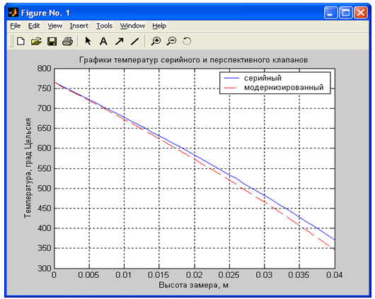
As calculated data distribution of the thermal field at a height of the valve taken the initial parameters obtained by Shiryaev[19] and is shown in fig. 4.
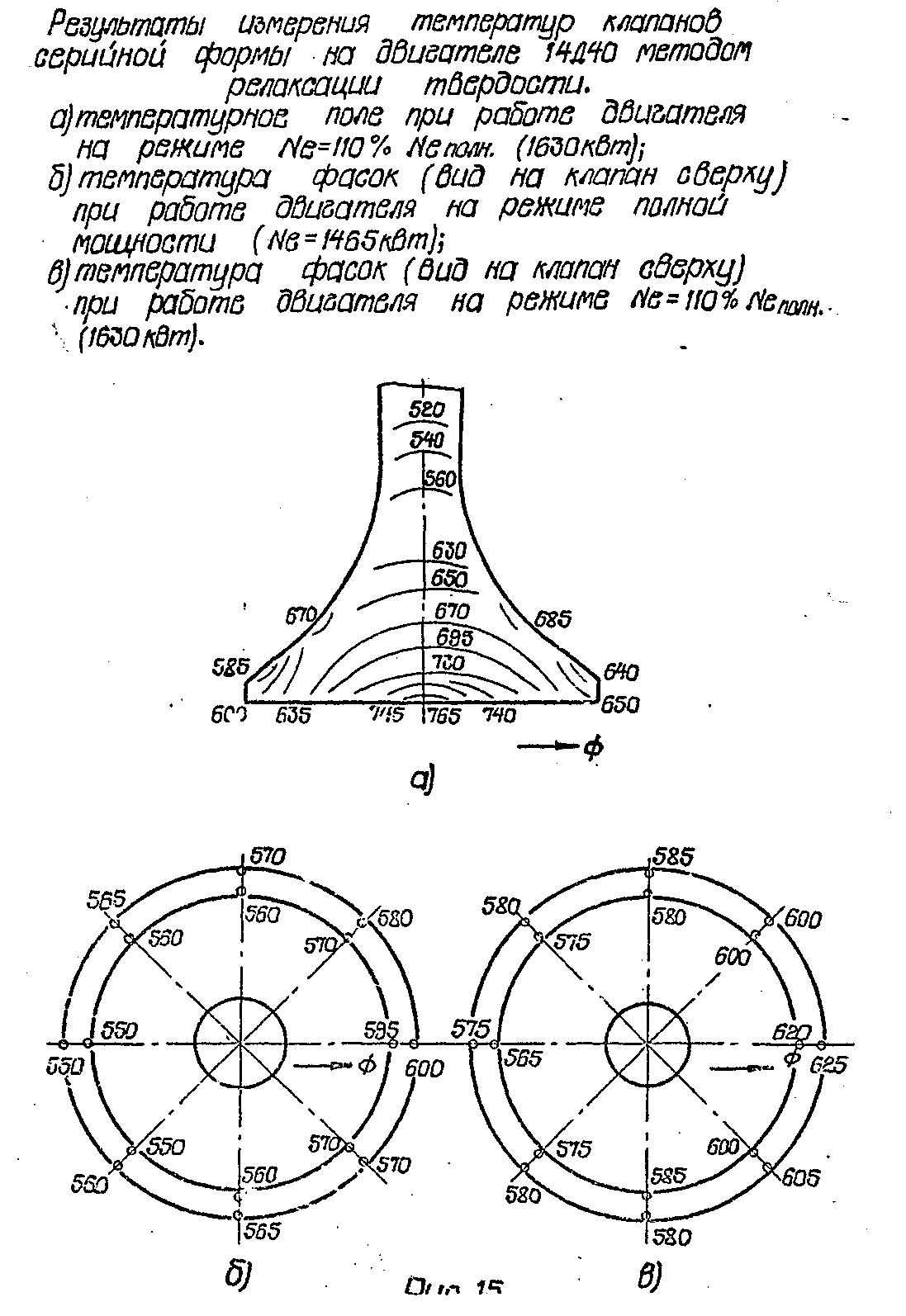
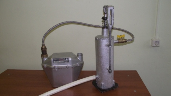
Figure 4. Calorific valve serial
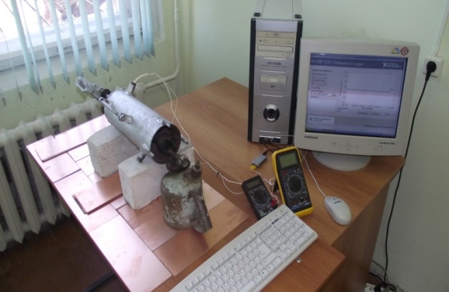
To confirm the analysis carried out studies on the capacity and thermal stress and the prospects for mass-tion valve diesel engine 14D40 experimental studies on the developed stands in fig. 5. and 6, and simulate how air and heat flows similar to those observed in the practice of operating a diesel engine 14D40.
Figure 5. Booth № 1
Figure 6. Booth № 2
As a result, respectively, were constructed graphs, allowing to evaluate the effectiveness of the proposed technical solutions in comparison with the serial.
To reduce the dynamic loads resulting in a collision with a saddle valve plates, proposed technical solution(RU2403408), and developed the physical and mathematical models to assess its performance.
Figure 7. Graph № 1
Figure 8. Graph № 2
This solution is shown in Figure 9 as a valve seat with a timing mechanism for internal combustion engines in the closed position, then open the saddle and the side view.
Figure 9. The design scheme
The work of the valve timing mechanism for internal combustion engines is due to the damping of the dynamic components of the stress in the process to close the valve which is facilitated by channels 7 and 8, as well as oral 9-nennye satisfied in the saddle, which creates aerodynamic resistance to the flow of exhaust gases, thereby unstressed landing valve plates in the saddle when it is closed.
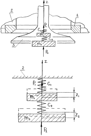
Figure 10. The design scheme
Figure 10 shows the design scheme, and below are the basic equations describing its dynamics. Write the equations of the kinetic and potential energy in the form:
(10)
and using the expressions obtained from the properties of positive definiteness and the sequence of quadratic forms defined by the values of the coefficients of inertia and stiffness:
а11 = m1 = P1/g, a12 = 0, a22 = m2 = P2/g,
c11 = c1 + c2, c12 = -c2, c22 = c2.
As a result, the dependence for calculating the frequencies of the main oscillations of the system of mass m1 and m2 of the form:
(11)
Having determined the frequency of normal oscillations of the system were calculated coefficients of the distribution and amplitude of dependencies:
Analysis of the structure of the proposed technical solution demonstrates that the presence of inductors in the saddle can dampen shock loads applied to the saddle as well as to the valve plate in the modes of closing it. Therefore, determining the mass flow of gas traversed by a W on the dependence of the throttle:
(12)
where the damping factor α(t) can be calculated by the formula:
(13)
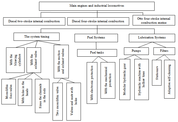
The method and timing recommendations on the design chosen on the basis of the results of research and incorporating approaches to prior selection of basic kinematic and geometric parameters, the definition of the limit values of the elemental base loading mechanisms and coordination parameters obtained and the conditions of internal combustion engines with the parameters of the recommended regulations for design and construction of diesel engines. The research allowed us to expand the classification of timing shown in fig. 11.
Figure 11. Extended classification of the internal combustion engine

4. Results

The analysis of the results on the calculation of changes in the area of channels and experimental studies on the passage of gas flow in the stand conditions of Fig 6, in the same direction shows that they are in good agreement with each other and the measurement error of the order of about 8.6%. At the same time, by analyzing the graph in fig. 7., It is evident that the thermal loading, upgraded valve in comparison with the serial below and the total error in the calculations compared with experimental data complied Shiryaev is 16.3%.
Analysis of the calculated values for mass and the proposed timing of diesel 14D40 shows that the shock load applied to the valve plate by contacting it with an upgraded seat, made under the patent RU2403408, declining an average of 1.91 times, which ultimately will increase the service life of given node of the timing of locomotive diesel engines.

5. Discussion and Conclusions

The analysis of the carried-out researches showed that the developed GRM constructional elements with reference to a diesel engine 14Д40 the inventions created at level (patents of the Russian Federation of RU2397336, RU2316655, RU 2433283), provide a reliable reroof of the chamber of compression of DVS and its exhaust collector, have the rational sizes of channels executed in plates and cores of valves and the exhaust gases intended for passing, reduce dynamic loadings operating on saddles of valves at their closing and reduce thermal stress of the last that creates conditions on increase of operational reliability not only GRM of locomotives, but also their DVS as a whole. At the same time, comparing bench experimental, constructional and technological indicators serial and prototypes of valves it is visible that the last are simpler on the device, are effective in work, less metal-consuming, are maintainable and technological in manufacturing. Results of research are recommended to the relevant scientific research institutes and the industrial enterprises of heavy mechanical engineering for further studying, completion and possible introduction of the offered technical solutions in practice.

References

[1]  Alimov V. N. Research of durability and durability of valves of the gas-distributing mechanism forced transport дизеля.//the Messenger of mechanical engineering. - 2001. - No. 12.
[2]  Anfinogenov M. A. Research of wear process of valves and the details of the diesel engine interfaced to it. Дисс. Cand.Tech.Sci.: - Novosibirsk. 1972. - p.
[3]  Balabin V. N. Mechanisms and bodies of a gazoraspredeleniye of transport internal combustion engines. Manual. M: MIIT, 2004,-61 page.
[4]  Balyuk B. K., Vakhtel V. Yu., Ermenko B. S. Increase of durability of the valve//Tractors and agricultural cars.-1966. - No. 11.
[5]  Betekhtin V. I., Zhurkov S. N. Temporary and temperature dependence of durability//durability Problems. – 1971.-№2.
[6]  Vakhtel V. Yu., Balyuk B. K. Determination of speed of a habit клапана.//Tractors and agricultural cars.-1963.-№8. - page 22-24.
[7]  Gas exchange in internal combustion engines: Uchebn. Grant / Century of G. Dyachenko. – To.: UMK IN, 1989.-204 pages.
[8]  Galgovsky Century of River, Karakulin I.F. About perfection of a design of final channels дизелей.//the Internal combustion engine.
[9]  Pigeon fanciers of Page. M. Grigoriev N. I. Dobrynin D. K., etc. Diknamika of modern domestic locomotives. M, 1964.123с.
[10]  Zubarev O. V., Brewers O.A.Modernizatsiya of four-cycle diesel DVS. Actual problems of technical science: Сб. научн. – Lipetsk: LGTU, 2009. – 286 pages.
[11]  Slivinsky E.V., Zubarev O. V., Brewers of the Lake. And. To synthesis of the perspective gas-distributing mechanism for duple and four-cycle diesel DVS. Control systems, technical systems: ways and research methods. Materials of interuniversity scientific and practical conference. EGU of I.A.Bunin. Yelets. Вып.3, 2011-230s.
[12]  Brewer O.A., Sirayev R. O. To a question of increase of efficiency of four-cycle diesel engines of industrial locomotives. Control systems, technical systems: ways and research methods. Materials of interuniversity scientific and practical conference. EGU of I.A.Bunin. Yelets. Вып.2, 2010 - 230с.
[13]  Slivinsky E.V., Savin L.A., Brewers of the Lake. And. Gas-distributing mechanism. Patent Russian Federation No. 2390638 from 27.05.10.
[14]  Slivinsky E.V., Savin L.A., Brewers О.А.К to a question of expansion of functionality of the perspective gas-distributing mechanism of four-cycle and duple diesel engines of locomotives. Control systems, technical systems: ways and research methods. Materials of interuniversity scientific and practical conference. EGU of I.A.Bunin. Yelets. Вып.3, 2011-230s.
[15]  Slivinsky E.V., Savin L.A., Brewers O.A.Mekhanizm of a gazoraspredeleniye of a diesel engine. Patent Russian Federation No. 2397336 from 20.08.10.
[16]  Slivinsky E.V., Savin L.A., Brewers of the Lake. And the Assessment of efficiency of use of the perspective gas-distributing mechanism of a four-cycle diesel engine тепловоза.ΙΙ the All-Russia scientific and methodical conference «Bases of design and a detail of cars – ΧΧΙ a century – the Eagle: ОрёлГТУ, 2010.-365с.
[17]  Slivinsky E.V., Brewers of the Lake. And. To a question of increase of efficiency of DVS at the expense of modernization of its gas-distributing mechanism. Control systems, technical systems: ways and research methods. Materials of interuniversity scientific and practical conference. EGU of I.A.Bunin. Yelets 2008-96s.
[18]  Brewers O.A.Razrabotka of the perspective gas-distributing mechanism for duple and four-cycle diesel DVS. Youth in a science: problems and prospects: the collection of materials of interregional congress of young scientists of Russia – Lipetsk: LGTU. 2008. – 351 pages.
[19]  Brewers O.A.Rasshireniye of functionality of diesel diesel engines at the expense of modernization of gas-distributing mechanisms of the [Text] / Lake. A.Pivovarov, L.A.Savin, E.V.Slivinsky//Izvestiya ORELGTU. World of transport and technological cars. – An eagle, 2012 No. 1 – page 48-52.
[20]  Brewers O.A.Sovershenstvovaniye of function of operation of the DVS gas-distributing mechanism by use of valves with a difficult gazodinamichesky path. Shock and vibrating systems, cars and tekhnologii./under the editorship of the Dr.Sci.Tech., the professor of H.p. Ushakov. – Eagle: ОрелГТУ, 2010-384 pages.
[21]  Brewers of the Lake. And. Pilot studies of capacity of the punched final valves of the gas-distributing mechanism of a diesel engine 14Д40 the [Text] / Lake.A.Pivovarov//Izvestiya ORELGTU. World of transport and technological cars. – An eagle, 2012 No. 2 – page 32-38.
[22]  Slivinsky E.V.Pivovarov O.A.Mekhanizm of a gazoraspredeleniye. The patent RU 2268373 C1 from 20. 01.06. Bulletin No. 02
[23]  Slivinsky E.V., Savin L.A., Brewer O.A., Increase of efficiency of use of constructional elements of diesel DVS. The collection of works of total scientific conference «About scientific potential and ways of its further development» - Lipetsk, LGTU, 2008. – 370 pages.
[24]  Slivinsky E.V., Savin L.A., Brewers O.A.Modernizatsiya of element base of gas-distributing mechanisms of diesel engines of the main and industrial locomotives. Engineering 2009: сб. works of a regional scientific and practical conference / edition stake.: L.A.Savin, P. G. Antonov, etc. Eagle: »Publishing house «The Oryol literature and a publishing house» and To», 2009. - 284с.
[25]  Slivinsky E.V., Brewers of the Lake. And. To a question of increase of efficiency of duple and four-cycle diesel diesel engines. Theory and practice of production of sheet hire [Text]: Сб. научн. тр. Part 2. - Lipetsk: LGTU, 2008. - 305с.
[26]  Slivinsky E.V., Brewers of the Lake. And. To a question of increase of efficiency of a diesel diesel engine at the expense of modernization of its gas-distributing mechanism. Materials of interuniversity scientific and practical conference. EGU of I.A.Bunin. Yelets, 2008-289s.
[27]  Slivinsky E.V of Brewers of O.A.Modernizatsiya of the perspective gas-distributing mechanism for duple and four-cycle diesel DVS. Actual problems of technical science [Text]: Сб. научн. - Lipetsk: LGTU, 2010. - 150с.
[28]  Slivinsky E.V., Brewers O.A.Rasshireniye of functionality of the gas-distributing mechanism of diesel engines of locomotives. Actual problems of technical science: Сб. научн. - Lipetsk: LGTU, 2009. - 286с.
[29]  Slivinsky E.V., Brewers O.A.Sovershenstvovaniye of gas-distributing mechanisms of diesel diesel engines. ΙΧ International scientific and technical conference «Vibration 2010. Operated vibrating technologies and cars» - Kursk: Kurskgta, 2010. - 58с.
[30]  Functional elements of diesel engines of locomotives. Constructional decisions. Design procedures: monograph / Lake. A.Pivovarov, L.A.Savin, Е. Century Slivinsky. - Eagle: ORLIK and K publishing House, 2010.-124 pages.