L. A. Savin , S. J. Radin cand. , E. V. Slivinskiy
Mechanical Technological Faculty, Elets State University I.A. Bunin, Elets, 399770, Russia
Correspondence to: E. V. Slivinskiy , Mechanical Technological Faculty, Elets State University I.A. Bunin, Elets, 399770, Russia.
| Email: |  |
Copyright © 2012 Scientific & Academic Publishing. All Rights Reserved.
Abstract
In given article questions on creation of perspective hydromechanical dampers of adaptive type are considered. The design procedure of the basic kinematic and geometrical characteristics on an example of one of them is offered. The analysis of the carried-out researches allowed to prove constructive characteristics of the offered technical solutions with reference to cars UAZ – 451М, ZIL – 131В and to the carriage, and also to other rail and trackless vehicles. Results of researches are recommended to design, research and machine-building structures for their possible use in practice.
Keywords:
Damper, Rod, Piston, Cylinder, Fluctuations
Cite this paper:
L. A. Savin , S. J. Radin cand. , E. V. Slivinskiy , "Hydromechanical Adaptive Dampers for Locomotives and Cars", International Journal of Traffic and Transportation Engineering, Vol. 1 No. 3, 2012, pp. 32-39. doi: 10.5923/j.ijtte.20120103.01.
1. Introduction
Aware that the existing design of hydraulic dampers have a number of shortcomings and the most significant of them is the complexity of construction, due to the availability of valve device, and therefore, low reliability, the inability to automatically modify your damper feature, and most importantly, not all the details involved in the process of energy dissipation.The crew part of locomotives and carriages consists of wheel pairs which are connected with a frame of carts and a body through system of elastic elements, balance weights, beams and the elements absorbing energy of fluctuations[1,2]. As a whole such devices name spring suspension. When wheel steams pass roughness of a way (joints a rail, details transfers, abyss etc.) In spring suspension there are dynamic loadings, including the shock. Thus, parts of crews test considerable accelerations on size. To occurrence of dynamic loadings promote as defects of wheel pairs, local defects of a surface of driving, eccentric landing of a wheel to an axis, an unbalance of wheel pair etc. Therefore, spring suspension, reducing accelerations structures and vertical loadings by it and the way, provides smoothness of a course to a rolling stock. To the basic characteristics of spring suspension carry total rigidity of steps of spring complete sets, degree of a damping and damping distribution on steps. The damping of fluctuations is carried out both in elements of suspension, and in specially intended devices - quenchers of fluctuations. Depending on the physical nature, forces of clearing subdivide on: Frictional, hydraulic and forces of a constructional damping. Size of a damping frictional quenchers estimate a zone of a friction of suspension δ, hydraulic quenchers - dimensionless parameter of damping D and quenchers of a constructional damping decrement of fluctuations δ/[2,5]. The Most simple on the device are frictional quenchers of fluctuations which are characterized by that dependence of force of friction F realized in them on relative speed of sliding of rubbing surfaces has rupture. Essential lacks of frictional quenchers of fluctuations are: the big forces of a friction of rest blocking spring suspension at revolting force, smaller force of a friction of a quencher that prevents to correct distribution of weight structures on the crew wheels, the raised deterioration of surfaces of a friction of details of a quencher, instability of creation of forces of resistance etc. The most widespread and effective now are hydraulic quenchers of fluctuations[1-5]. The principle of their action consists in consecutive moving of a viscous liquid by the piston through narrow channels, as a result there is a transfer of mechanical energy in thermal to its subsequent dispersion in environment. At designing of such quenchers force of its resistance define proceeding from speed of relative deformation of mobile elements and factor of proportionality which is quencher parameter. The design of a modern hydraulic quencher represents the working cylinder in which the rod with the piston is movably located, and last is supplied by valves with throttle apertures. The same valves are available in the bottom of the working cylinder. The working cylinder is in the oil tank. For increase of smoothness of a course of locomotives and cars hydraulic quenchers of fluctuations establish in the leaning position in the second step of spring suspension that allows to extinguish not only dynamic components of vertical loadings but also horizontal. Despite the efficiency of use such quenchers possess a number of lacks and most essential of them are – complexity of a design, at the expense of presence valve devices and consequently also low reliability, impossibility in an automatic mode to change the damping the characteristic, and all its details participate in energy dispersion not.
2. Objectives
Considering the above-stated, in Bunin’s ELSU and OSTU, working out of practical recommendations about increase of reliability, technical and economic, technological and operational indicators is spent research on a theme «at operation and repair of a rolling stock and other equipment used on Yelets branch of the Southeast railway» and one of its sections is working out of perspective dampers for the main, shunting and industrial locomotives, and as carriages. The analysis of research reports in this area of technics, references, domestic, and foreign patents has allowed to develop more simple and effective on a design adaptive hydromechanical shock-absorbers which can be used not only on locomotives, but also cars. Such designs are recognized by inventions: RU 2230241, RU 2234013, RU 2247269, RU 2268419, RU 2301363, RU 2317456, RU 2324090, RU 2324089, RU 2324087, RU 2324088, RU 2339856, RU 2371617, RU 2385425, RU 2388949, RU 2390638, RU 2427742, RU 2427741, RU 2427740, RU 2427738. Therefore the purpose of work is carrying out analytical researches on determination of kinematic and geometrical parameters of an adaptive hydromechanical damper of fluctuations, manufacturing of a model sample and carrying out pilot studies of the last in bench conditions.
3. Methods
The essence of the offered technical decisions consists that pistons are supplied by vertical throttle channels which pass to sites of channels "Г" of the figurative form executed in inflow, adjoining with a backlash to radially located edges, and the mentioned pistons are rigidly fixed on rods of continuous and hollow sections. Quencher work occurs in such a manner that at a working course and return rods are exposed to pure torsion, disseminating thus energy at such angular deformations, simultaneously creating forces of resistance at the expense of course of a working liquid through throttle channels. For the analysis of working capacity of such quenchers of fluctuations and calculation of their basic kinematic and geometrical parameters, settlement schemes have been developed and known techniques on studying of law of working process are used at an unsteady mode of a damper in the conditions of close to the operational. The program complex therefore rational geometrical values of diameters of elastic rods of the quencher answering to set reliability of their work in operational conditions are proved is developed for the numerical decision of mathematical models.Let's take as an example, one of the options proposed technical solutions (RU2385425), which most fully reflects the construction associated with the creation of Adaptive Hydromechanical dampers.This type of Adaptive Hydromechanical damper (fig. 1) consists of working cylinder 1, which is fluid in stock 2 its vertical plane located the upper part 3 of the piston and lower part of the piston 4. This parts are connecting with rod 2 performed by groove 5, manufactured by rod 2 and keys 6 located on the top of the piston 3 and the lower part of the piston 4. At the top of the piston 3 and the lower part of the piston 4 implemented vertical channels 7, turning into horizontal channels 8 and ribs 9. Between the top of the piston 3 and the lower part of the piston 4 installed compression spring 10, while at the lower part of the piston 4 implemented additional vertical channels 11, turning into horizontal sections of 12. The upper part of the piston 3 and lower part of the piston 4 fixed by emphasis 13 on the rod 2 and nut 14. Working cylinder filled with fluid 15. The upper part of the piston 3 equipped with a cylindrical deepening 16, and the lower part of the piston 4 has guide 17.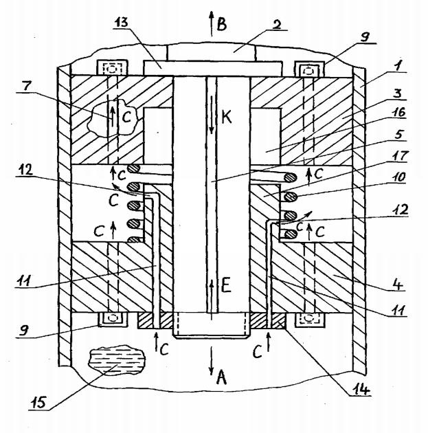 | Figure 1. Hydromechanical damper |
The device works as follows. When the vehicle is in motion, in which his suspension can be installed in the dampener fluctuations and breaking his wheel track ruts can be periodic working rod 2 arrow and return it to drop in this case the amplitude of rod 2 and therefore the top of the piston 3 and lower part of piston 4 occur together without causing elastic deformation compression springs 10. The working fluid 15, for example, in the working stroke, tributary of the arrow C, getting into additional vertical channels 11, doing in the space between the top of the piston 3 and lower part of the piston 4 also the arrow C. Further the working fluid 15 comes in both vertical channels 7 the lower part of piston 4 and top of the piston 3 and, until the pressure of horizontal channel 8, interacts with ribs 9, creating a torque on the rod 2. Rod, elastic deformation an on its longitudinal axis of symmetry, disperses the energy of the environment. When the rod 2 in a retreat by the arrow B in the current fluid 15 occurs in the direction of reverse arrow С and damping process is similar to the above. Suppose that the path has been pretty much roughness and vehicle wheel impacts it is hit, and then the lower part of the piston 4 under the influence of pressure working fluid 15 will move the arrow E, the elastic by twisting the spring compression 10. This movement at the lower part of the piston 4 will be accompanied by a guide 17 in cylindrical deepening 16 the top of the piston 3 and then the current working liquid 15 into additional vertical channels 11 reduced by overlapping their horizontal stations 12 by guide 17 and deepening of cylindrical form 16. As additional vertical channels 11 have different diameters and are incrementally with each other on height, cancelled the load increase, and the work of a damper will be more effective. In a mode of return of a damper there will be a movement of the top part of the piston 4 will move the arrow K, as above will cause the elastic deformation of compression springs 10, together with the overlay of additional vertical channels 11 and then the working fluid will not be able to proceed in the direction opposite arrows C with that would also enhance the resistance of the rod and the effectiveness of such dynamic shock cushioning. Further steps can be repeated many times.The mathematical model is developed for an estimation of geometrical and kinematic parameters of the offered design of the hydromechanical shock-absorber[3]. At formation of mathematical model the known equations of dynamics, the elasticity and hydromechanics theory are used. As the basic accounting ratios accepted equation of concentrated mass m0, which in cases of power, kinematic and mixed excitation is: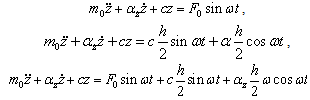 | (1) |
where m0 - the sprung mass of the crew, kg;с - rigidity of an elastic element of spring suspension, N/m;αż - variable damping factor, N∙s/m;z - generalized coordinate, m;h - height of roughness, m;ω - frequency of oscillation of the body's crew, s-1.Known[4, 5] that the damping factor αż depends on the hydraulic resistances in the channel for cushioning, shock absorber fluid viscosity, turbulence and flow it can be determined by the formula: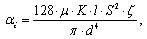 | (2) |
where μ - dynamic viscosity coefficient, N∙s/m2;l - total length of the throttle channel, which includes the length of the vertical and horizontal plots, m;S - reduced piston area, m2;d - the equivalent diameter of throttle channel, m;ζ - coefficient of resistance head for cushioning channel;K - generalized coefficient, taking into account the influence of turbulence flow and local resistances for bandwidth throttle input with sharp edges.The last factor is defined as: 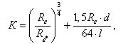 | (3) |
where Re* - critical Reynolds number and Reynolds number Re:  where ν - kinematic viscosity fluid, and Vср - average speed it flow and it can be calculated by the formula
  In the latest dependence VП progressive piston velocity dependence, and n the number of chokes and fк cross-sectional area of one throttle. As a result, you can set the numeric value of the equivalent diameter of throttle channel conditions change square cross-section with angular movements of rod by the formula:
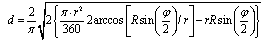 | (4) |
where r - the radius of the throttle channel 12 carried out on the ledge 17 of the lower half of the piston 4;R - radius of the location of throttle channels on crest of 17.Because when the piston is pure torsion rod, an absolute angle of twist can be defined by dependency:  the torque rod is
  where the district effort due to the fluid flow at the edges of the piston is defined according to halves
 . In this equation is an important parameter is the instantaneous flow fluid w, which can be calculated by the formula:
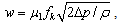 | (5) |
where μ1-coefficient of the working fluid, depending on its viscosity, the pressure drop in the throttle channel their form and size.After the establishment of a regime of working liquid and compare it with the critical value of Re(кр) you can define the pressure her dependency: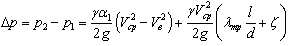 | (6) |
where α1 - Coriolis coefficient;λтр - resistance factor of working fluid on a straight stretch of channels of piston and guide 17.Analyzing set out how you can see that unknown in the equations are the movings of element base of a damper on an axis z, damping factor αż , equivalent diameter d, angular displacement of rod φ, torque Tкр, district force F1, instant consumption w and pressure Δp.The methodology used when calculating the rational parameters above design shock absorber under which conditions the efficiency of the vehicle specified vibration protection frequency range of external influences. To evaluate the health of proposed designsHydromechanical dampers adaptive type during the period 2008-2009 in science laboratory in Bunin’s ELSU manufactured layout designs advanced hydraulic silencers systems fluctuations performed under patent RU2230241 and tested in bench conditions compared with conventional models.Such dampers had overall characteristics similar to serial designs type MKZ and KVZ widely used in the suspension brackets of modern vehicles such as automobiles UAZ-451M, ZIL-131V and compartment passenger carriage length of 24.6 meters. Figure 2 shows, for example, the exhibition sample prospective damper designed for the compartment all-metal passenger carriage length of 24.6 meters. The damper consists of working cylinder 1, a solid rod of circular cross-section rod hollow ring 2, section 3, the top half of the piston 4, lower half of the piston 5, sealing rings 6, enclosure, with a lower and upper drawbar eye during the 7 and 8, rod guide compaction 9, nuts 10.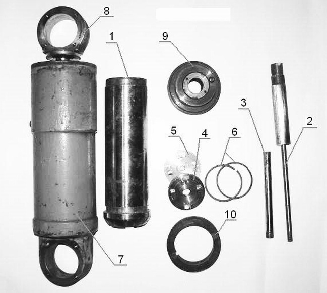 | Figure 2. The model sample of a hydromechanical damper |
Experiments were conducted during the period of December-March 2008-2009 on stand designed by using the cross-section-planning machine tool model 7A33 (fig. 3) have been carried out comparative experimental study on power load, three layout designs of Hydromechanical dampers performed under patent RU2230241 and production models used for the above vehicles. On a machine using slide pusher force hinge bracket fixed chassis serial or hydromechanical damper, rod also jointed joins arm rigidly attached to its base plate using bolts installed on a desktop machine. At rods, both solid and hollow cross-section as serial and layout samples of dampers were pasted tensoresistors located on the base 5 mm towards each other at an angle of 90 degrees and locking torques Tкр arising at rods with longitudinal their movements. The tensoresistors using shielded cables were connected to the amplifier ТУП-12М, oscilloscope model C1-55. For recording waveform on paper the oscilloscope as the cable is attached to the computer system unit. Using the printer connected to the system unit, was a printout of the waveform.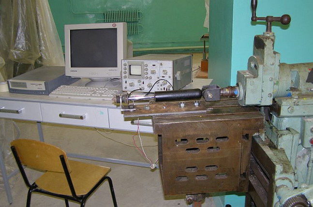 | Figure 3. Experimental researches of a hydromechanical damper |
Test each of the above samples are made according to the available literature and works on power load fluctuations, and efficiency of dampers of various rail vehicles as follows[6, 7]. Having analyzed a damper fluctuations on the stand and consecrate it to the appropriate brackets, the rod was half full stroke and stroke cross machine installed 50 mm. Operator set stroke the cross-section-planning machine tool on the amplitude of the linear motion of 50 mm and chose his progressive speed corresponding to a frequency move slide equal to fluctuations in the second. At the same time fixing the character of change of loadings and torque moments host oscilloscope and then on the printer. Record each waveform over 10 seconds. Experiences were spent in fivefold frequency on each of investigated designs of shock-absorbers. As a result waveform were received, of which two examples are shown in fig. 4 and recorded for damper model KVZ for passenger carriage with a length of 24 m.Left figure provides the inertia forces of the waveform follows a change Pи for serial and pilot damper and right figure - torque Mкр at its rods.Waveform processing these phases of tests carried out on the basis of numerous papers[8] on the statistical processing of experimental data. Measurement of peak amplitudes have been using the meter with an accuracy of 0.3 mm and the reference value in a number of peaks have distribution in ascending number of repetitions. A graphical representation of statistical series in the form of histogram was a stage when choosing a distribution law and calculation it was found that the distribution correspond to the normal distribution law. Tests showed that the normal distribution curves correspond to statistical number satisfactorily that evidenced by found criterion consent Pearson, for the example is based on an average between 0,613 to 0,232. Total error of waveform processing lies within the tests from 0.68 to 6.1%, and the average error for all experimental data is 6.63%.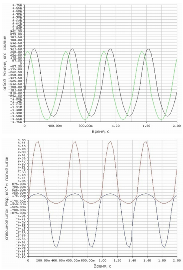 | Figure 4. Waveform |
4 Results
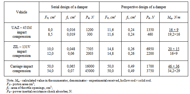
As a result of computing experiment on modeling system "wheel-damper-body" are received in the form of schedules of dependence of variable factor of a damping αż (fig. 5, 6), based on the use of generalized mathematical models and these using MathCad software package, and also algorithm (fig. 7) calculation of parameters of hydromechanical damper.Analysis of the numerical solutions and the graphs shows that the effectiveness of vehicle vibration damping is achieved by a set of active resistance to the process of the piston motion and angular turns elastic rod above design of Hydromechanical damper hesitation to mechanical and hydraulic components of the resistance movement. While varying in a wide range of throttle diameter value channels, step their horizontal sections and stiffness of elastic connection between halves of the piston (fig. 1), as well as the viscosity of the fluid, you can obtain optimal of variable factor of a damping αż, directly associated with the smooth running of various construction rail vehicle.As a result of studies, taking into account the statistical processing of received waveform are average values of the characteristics of the parameters, the numbers are presented in table 1.As an example, look at the registered parameters of damper variations used in designs for pendants UAZ-451M. For example, table 1 shows that if serial sample load disconnect compression modes and damper respectively represent 1200 N and 300 N, the prototype they slightly above and also for appropriate modes of retreat and compression are 1350 N and 460 N. shows that they increased by an average of 11.1 and 34.8% respectively and have slightly higher resistance at a damping. This increase in workload due to the fact that its growth is aimed at creating torque arising at rods annular cross section and a solid round, equal respectively 19.2 and 16 N∙m, which facilitates the dispersal of energy in the day when clean and compress the torsion rod. Therefore, you can take it that the damping ability of the test sample damper in this case would be more effective than normal. It should also be noted that the convergence in Mкр estimates compared with experimental data demonstrate consistent average of 28.2% (estimated value of Mкр, impact and compression are 16 and 9 N∙m).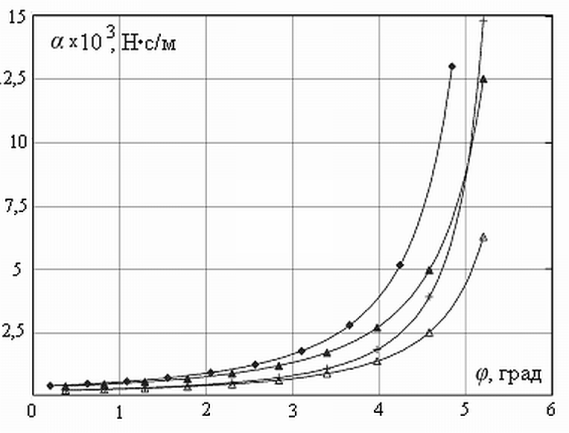 | Figure 5. Dependence of factor of a damping αż on an angle of rotation of a rod φ |
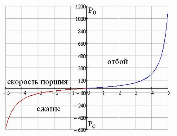 | Figure 6. Dependence of forces of resistance of the shock-absorber on speed of moving of the piston on courses of compression and a release |
Table 1. Results of experimental researches
 |
| |
|
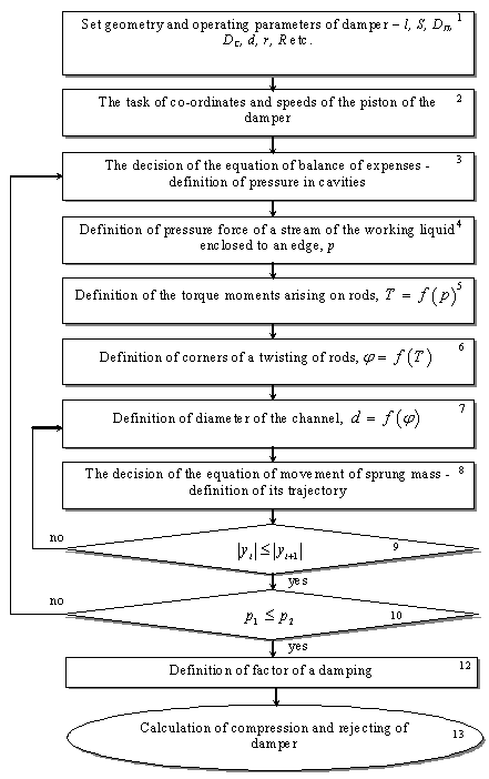 | Figure 7. Algorithm of calculation of factor of a damping and working efforts and moments of the damper |
5. Discussion and Conclusions
Analysis of bench experiments showed that the Hydromechanical dampers, executed on patent RU2230241, contributes not only to concentrated forces contributing to the curvature of the fingers to structural elements of fastening spring suspension and vehicle crew and flexural moments. However, such load elastic bellows are located in eye rings of rods and damper’s case that allows you to create additional reactive bending moments involved in energy dissipation and waking moments, compression together with by at rods ring and solid sections of a dampers. At the same time, comparing the test pilot, constructional and technological parameters of serial and prototype of Hydromechanical dampers can be seen that the latter are easier on the device, do not have complex spillway valves are robust, maintainable and easy to handle in manufacture. Results of research are recommended for the further studying, completion and possible introduction of the offered perspective quenchers of fluctuations at the enterprises of domestic and foreign mechanical engineering.
References
| [1] | N.S. Konarev, Railway transportation: the Encyclopedia, 559, 1994. |
| [2] | I.I. Chelnokov etc. Quenchers of fluctuations of cars., 165, 1963. |
| [3] | E.V. Slivinskij, A.A. Zajtsev, S.JU. Radin, “Perspective a design of a hydraulic quencher”, Journal the Locomotive. 10, 2007. |
| [4] | I.M. Babakov, «Theory of fluctuations», 1968. |
| [5] | A.D. Derbaremdiker, “Hydraulic shock-absorbers of cars”, 200, 1985. |
| [6] | V. S. Lihachyov, “Test of tractors. The manual for high schools”, 228, 1974. |
| [7] | E.A. Pisarevsky, “Electric measurements and devices”, 432, 1979. |
| [8] | E.I. Pustilnik, “Statistical methods of the analysis and processing of supervision”, 288, 1968. |
| [9] | Savin L.A., Slivinsky E.V.Element base of hook-on vehicles (Monograph). – Eagle: Eagle of GTU, 2008. – 296 pages. |
| [10] | Slivinsky E.V Improvement of a design of devices and knots of autotractor trains: the monograph - Yelets: EGU of I.A.Bunin. 2009. – 236p. |
| [11] | Slivinsky E.V Modernization of element base of running gears of autotractor trailers. «Repair, restoration, modernization». Monthly production, scientific and technical and educational and methodical magazine. M: Prod. JSC Nauka i tekhnologii, No. 6, 2009. – 8p. |
| [12] | Slivinsky E.V, Savin L.A, Radin S. J. Ways of improvement of running gears of vehicles: the monograph - Yelets: EGU of I.A.Bunin. 2009. – 240p. |
| [13] | Korchagin V.A., Slivinsky E.V., Rizaeva J.A. Improvement of maneuverability of supersize road trains. World of transport and technological cars. Eagle.: The scientific and technical magazine No. 3, ORYOLGTU, 2010 – 112p. |
| [14] | Slivinsky E.V. To a question of increase of traffic safety of automobile trains. «Motor transport: operation, service, repair». Technological magazine, M: Panorama publishing house, No. 11, 2010г. – 23p. |
| [15] | Slivinsky E.V. The device excluding folding of links of a supersize road train at braking. «Repair, restoration, modernization». Monthly production, scientific and technical and educational and methodical magazine. M: Prod. JSC Nauka i tekhnologii. No. 12, 2010-23p. |
| [16] | Korchagin V.A., Slivinsky E.V. Increase of traffic safety of supersize road trains. Bulletin of transport information. M: Transport No. 4. 2011-210s. |
| [17] | Slivinsky E.V, Savin L.A, Radin S. J. Hydraulic damper. Construction and road cars. - 2010. - No. 9. - Page 62. Equipment - Invention and rationalization. Patent business. |
| [18] | Slivinsky E.V.Modernization and ways of improvement of trains of vehicles. LAP LAMBERT Academik Publishing CmbH & Co KG Dudweiler Landstr (monograph). 99, 66123 Saarbrucken, Germany 2011. 471 p. |
| [19] | Korchagin V.A., Slivinsky E.V., Rizaeva J.A. Increase of maneuverability of road trains and efficiency of their work at the expense of use of the new sedelno-coupling device. Bulletin of transport information. M "transport": No. 1, 2012 – 22p. |
| [20] | Korchagin V.A., Slivinsky E.V., Rizaeva J.A. Increase of effective operation of vehicles at the expense of a new design of an independent suspension bracket. Science and equipment to transport. M: No. 1, 2012, 23p. |
 Abstract
 Reference
 Full-Text PDF
 Full-Text HTML