-
Paper Information
- Next Paper
- Paper Submission
-
Journal Information
- About This Journal
- Editorial Board
- Current Issue
- Archive
- Author Guidelines
- Contact Us
International Journal of Traffic and Transportation Engineering
2012; 1(2): 7-12
doi: 10.5923/j.ijtte.20120102.01
Bus Route Information Retrieval through Visual Codes Using Camera Enabled Cellphones
 Abstract
 Reference
 Full-Text PDF
 Full-Text HTML
K. Ganesan 1, Javed A. Rahman 2, Surbhit Jain 2
1Director, TIFAC-CORE in Automotive Infotronics, VIT University, Vellore, India
2School of Computing Sciences , Engineering, VIT University, Vellore , 632 014, Tamil Nadu, India
Correspondence to: K. Ganesan , Director, TIFAC-CORE in Automotive Infotronics, VIT University, Vellore, India.
| Email: |  |
Copyright © 2012 Scientific & Academic Publishing. All Rights Reserved.
City buses are a cheap and convenient way of commutation around the globe. Such buses have identification numbers which determine the route of the bus round the city. These identification numbers are known to the daily local commuters of the bus service, but are a great problem for outstation tourists who are not aware of the bus numbers. In some cases the bus route itself is printed on the bus, this in most cases is again in the local language of that place and is hence a problem for the outstation tourists due to the language barrier. In this paper we present a system to overcome this situation. We propose to encode the bus identification number of a bus in 2-dimensional visual codes. These visual codes can be easily be either printed on the buses or on the bus stops. Further we develop a mobile application that uses the embedded camera of the cell phone to snap a picture of such a visual code. The image taken is then processed on the cell phone itself to retrieve the bus identification number from the visual code which is then sent to the server device ( through a text message) containing the database of bus route of all the buses. The server device looks up the database for the bus route information corresponding to the received bus identification number received and sends it back to the client cell phone through a text message.
Keywords: Visual Code, Sms, Mmapi, Adaptive Thresholding, Labeling, Major , Minor Guides, Cornerstones, Midlet
Article Outline
1 Introduction
- Camera equipped cell phones have become a norm in today’s market. Camera enabled cell phones are now equipped with cameras having high resolution capabilities. Such phones also have high processing capabilities and are loaded with fully functional operating system such as Symbian or Android OS and are commonly referred to as Smart Phones[1,2]. Such devices can be successfully used for providing information to the user due to their ubiquity[3,4]. In this project we have developed a system that turns such cell phones into sensors for 2-dimensional Visual Codes. The system used here consists of mainly three parts. First the 2-dimesional code (Visual Code[5]) encodes the bus identification number, second an application running on the cell phone accesses the embedded camera to capture the picture of the 2D code and decodes it to retrieve the identification number. This bus route identification number retrieved from the Visual code is then sent to a server through a text message containing the database of bus routes of all the buses. The server looks up the database for the received bus identification number and sends it back to the client cell phone through a text message.The main motivation behind the development of such a system is to use the camera of cell phones as another way of user input. This kind of user device interaction technique is useful in situations where long bus numbers have to be fed onto the cell phone[6,7]. In this paper, in section 2 we discuss about the 2-dimesional code standard used namely Visual Codes[5] and why it is suitable for our application. In section 3 we present a brief architecture of our system. Furthermore in section 4 we design an image recognition algorithm to recognize the visual code and retrieve the information associated with it. Development of the recognizer mobile application and the development of the server application containing the bus route database are devoted to section 5. In the Last section 6, we enumerate our conclusions.
2. The Visual Code
- In this paper we work with a 2D code standard[8,9] namely Visual Code[5]. The typical phone camera generates low to medium quality color images in VGA (640 × 480 pixels) or lower resolution. The relatively poor image quality is taken into consideration while designing and choosing the code standard. The Visual Code standard that we use has been developed by Michael Rohs, Beat Gfeller of Institute for Pervasive Computing, Department of Computer Science, Swiss Federal Institute of Technology (ETH) Zurich[5].The code consists of the following elements: 1. A larger and a smaller guide bar for determining the location and orientation of the code.2. Three cornerstones for detecting the distortion.3. The data area with the actual code bits.
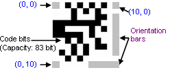 | Figure 1. Anatomy of a Visual Code |
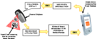 | Figure 2. System Architecture |
3. System Architecture
- To start with we consider how to encode the bus number/bus stop ID number in a Visual Code. For this we assign the bit pattern 0001 (1 in decimal) to the Bus Route Retrieval application. Thus all the Visual Codes containing a bus number/bus stop ID number will have this bit pattern. Now to encode a 10 digit bus number and the 9 digit bus stop ID number in a Visual Code we need 76 bits out of the 83 bits of the Visual Code. Each four bits can be used to represent a number in the hexadecimal format. We append a binary 0 to the 83 bits making it 84 bits to even up the calculations. Thus the following representation is stored in our Visual Code.Bit 1 - 4 – 0001 (Code for bus route information retrieval application)Bit 5 - 76 - 10 digit Bus number and 9 digit Bus stop ID number(Each alphanumeric number is represented in binary using four bits)Bit 77 -83 - Binary 0 (0000)Figure 2 shows diagrammatically the overall architecture of the system. The camera enabled cell phone uses the developed recognizer application to take an image of the visual code containing bus number/ bus stop number ID and decodes it to retrieve the identification number which is then sent to the server containing a database of the bus routes through a text message. The server looks up the database and sends the corresponding bus route information back to the camera phone through a text message.
4. Recognition Algorithm
4.1. Design of Recognition Algorithm
- The mobile phone devices we considered have severely limited computing resources and often lack a floating point unit. Hence, the use of floating point operations has to be minimized or avoided. The typical camera phone generates low to medium quality color images in VGA (640 × 480 pixels) or lower resolution. The relatively poor image quality determines the minimal size of code features that can be reliably recognized. Because of the mobility inherent to camera-phones, scanned codes might appear at any orientation in the camera image. They can be arbitrarily rotated and tilted; we have to design an algorithm that can successfully recognize such images also[10,11]. Our recognition algorithm performs the following main steps on the camera image and produces a code.
4.1.1. Acquiring Image from Camera
- The camera equipped cell phones available in the market are fitted with a video/still camera based on the CCD technology. We can acquire the image from the camera integrated in the cell phone by using the Multi Media API (JSR – 135) available in J2ME[12]. In our image acquisitions following specification were used:Resolution: 160 x 120 pixelsFormat : PNG Mode : Color (RGB)
4.1.2. Gray scaling
- To produce a grayscale version of the acquired image we used the formula Y = (red + green)/2 instead of the ITU formula Y = 0.2126 × red + 0.7152 × green + 0.0722 × blue. The blue component is omitted as it has the lowest quality in terms of contrast and sharpness. This largely decreased the computation time required for the gray scaling operation.
4.1.3. Thresholding
- The main aim of processing the acquired image is to identify the guide bars and the corner stones present in the visual code. The resulting grayscale image consists of only 256 shades of gray. But identifying the pixels of our interest namely the guide bars and the corner stones is a much difficult task in this gray scaled image. Thresholding the image to a certain gray value we get a binary image (i.e. image containing only black and white pixels) which simplifies the process of segmentation and labeling.
4.1.3.1. Static Thresholding
- Performing a thresholding operation by fixing a fixed threshold limit (85% gray value or using its hexadecimal equivalent represented by 0x5f5f5f) gives an optimum result in most of the situations. But in some cases when unwanted clusters of black pixels mingled with the visual code, they made the recognition of visual code very difficult. This was mainly due to brightness of the camera not being constant and image often being ill-illuminated. Thus to overcome the problem we decided to use Adaptive thresholding (i.e. fixing the threshold limit to the average of the gray values of all pixels present in the image and not using a constant value for all images).
4.1.3.2. Adaptive Thresholding
- The basic idea here is to divide the image into four equal parts and to use different threshold values for each part were calculated. Furthermore the threshold value for each of the part were not static but were rather calculated using a weighted moving average of the gray values while running through the image in a snake like fashion[13] (alternating from left pixel to right pixel in one line and from right pixel to left pixel in the other line). The adaptation takes the previous scan line of each examined scan line into account in order to avoid artifacts in every other line, resulting from the zigzag traversal of the scan lines. Gray scaling and adaptive thresholding turned out to be the most time consuming phase our recognition process. Therefore, we replaced any floating point operations in this part by shifted integer operations, which resulted in a significant performance improvement.The average gs(n) is updated according to:- gs(n) = gs (n − 1) · (1 −(1/s) ) + pnwher pn denoting the gray value of the current pixel s = 1/8w the width of the moving average (w is the image width) gs is initialized with gs(0) = 1/2cs, where c is the maximum possible gray value. The color of the thresholded pixel T(n) is chosen as (t = 15)T(n) = { 1 if pn < gs(n) / s . 100 - t /1000 otherwise
4.1.4. Labeling
- This step consists of finding regions of neighboring black pixels, counting them, and assigning a number to each. Each pixel of the image is traversed from the starting, if the pixel is black and another black pixel lies in its neighborhood then the same region code as that of the pixel in neighborhood is assigned to the current pixel else a new region code is assigned. The algorithm we use is a well known two-phase method: 1. In the first phase, the image is traversed row by row, assigning preliminary labels to the regions found. During this process, it may happen that two regions with different labels turn out to be in fact the same region. In this case, the equivalence of the two temporary labels is stored in a table. 2. The second phase resolves the equivalencies by merging the corresponding regions and assigns a final label to each region.
4.1.5. Calculation of Second Order Moments
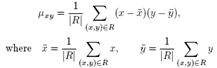
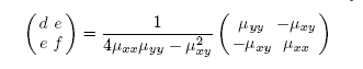
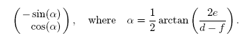
- In order to identify candidates for orientation bars among the clusters found, the notion of second-order moments[14] is used. In each of the region we draw an ellipse to find their eccentricity which helps us finding the regions with correct shapes corresponding to the orientation bars in the Visual Code. The ratio of the lengths of the major and the minor axis is a good measure for the “eccentricity” of the cluster: perfect circles and squares have a ratio equal to one whereas line segments have a ratio close to zero. This is very useful to identify clusters with a bar-like shape. Furthermore, the orientation vector of the major axis of the cluster can be calculated as to deal with tilted visual codes. The second-order moments of a cluster consisting of a set of pixels R is mathematically defined as follows
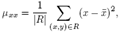 | (1) |
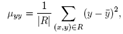 | (2) |
 | (3) |
 | (4) |
 | (5) |
 | (6) |
4.1.6. Locating the Guide Bar Candidates and Cornerstones
- Locating codes in the image is done by looking for guide bar candidates and by finding corresponding cornerstones. Guide bar candidates are found by simply selecting those clusters which have a small enough axis ratio (e.g. below 0.05). For each of these candidates, the size and orientation of the cluster is used to estimate the expected position of the second guide bar (the smaller one) and the three cornerstones. It is then checked whether these features are actually present at the estimated positions.
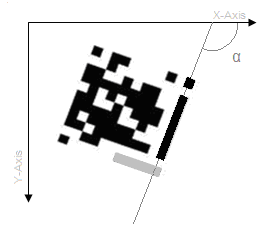
4.1.6.1. Finding the Major Guide
- The major guide has one unique property i.e. it is the only region in the entire image that will have an eccentricity is close to 0.05. This is for the fact that for major guide the height is equal to seven times its width. Thus the major guide can be easily identified by checking the eccentricity of each of the region identified. We can also find out the angle (α) the region (i.e. the major guide) makes with the x-axis of the co-ordinates system as shown in figure 3. This is extremely important in cases where the Visual Code is tilted.
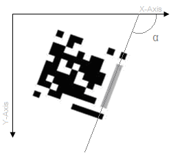 | Figure 3. Major guide |
4.1.6.2. Finding the minor guide bar
 | Figure 4. Minor guide |
4.1.6.3. Finding the Upper Right Corner Stone
- The Right upper corner stone is identified in a similar way. To identify Right upper cornerstone we select the first region that the line drawn from angle α with the positive direction of the x-axis of the co-ordinate system passes through as shown in figure 5. To verify further that the region is indeed the minor guide we check its eccentricity. The eccentricity of the minor guide should be approximately 1. This is so due to the fact that the cornerstone is a square and thus the ellipse enclosed would be a perfect circle whose eccentricity would be 1.
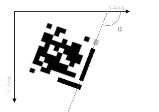 | Figure 5. Minor guide |
4.1.6.4. Finding Lower Left Cornerstones
- To find the lower left cornerstone of the Visual Code we now draw a line that passes through the major axis of the minor guide which makes an angle of 90 degrees with the line passing though the major axis of the major guide as shown in figure 6. Now we search for the last region that passes through this line. Furthermore we check the eccentricity of the last region that passes through this line. If the eccentricity of this region is approximately 1 then this region is marked as the lower left cornerstone.
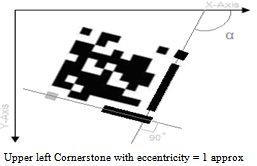 | Figure 6. Lower left cornerstone |
4.1.6.5. Finding Upper Left Cornerstone
- To find the upper left cornerstone we draw a line that passes through the centre of the upper right corner stone which makes an angle of 90 degree with the line passing through the major axis of the major guide. Then similarly we draw a line that passes though the centre of the lower left cornerstone which makes an angle of 90 degree with the line passing through the major axis of the minor guide as shown in figure 7. Then we find the region where these two lines intersect and further find the eccentricity of that region. If the eccentricity of the region is approximately 1 then we mark this region as the upper left. Thus after successfully finding the five structural components (major guide, minor guide and the three cornerstones) of the Visual Code we enclose it in a square. Now we draw a 11 x 11 grid on the square and find the value of the pixel at the centre of each cell. If the pixel is black then it represents binary 1 else 0. Thus we get the 121 bit binary output out of which we subtract 38 bits representing the structural components and its nearest neighbors of the Visual Code. The remaining 83-bits are decoded.
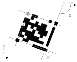 | Figure 7. Upper left cornerstone |
5. Design of Recognition Algorithm
- The algorithm discussed in section 4.1 was implemented using a Java applet on a PC. As the final mobile application has to be developed in J2ME, thus porting the code to the mobile application would be easy. Images taken from the camera of the cellphone were provided as input to the recognition algorithm which then displayed the 121 binary bit pattern encoded in the visual code
6. Recognizer Mobile Application
- Figure 8 shows the snapshot of the camera view finder window that allows the user to snap the image of the Visual Code. The second snapshot shows the SMS confirmation dialog which is displayed after the visual code is successfully decoded ant the user is asked if it wants to send the bus number bus stop ID number to the server mobile device as a text message. The third snapshot shows the final result i.e. the bus route information that is received from the server mobile device. The recognizer mobile application is developed in J2ME as it can be ported on a large number of mobile devices available in today’s market. Due to floating point computations involved in the recognition algorithm, phones that support CLDC 1.1 and MIDP 2.0 are required to run the application[15]. The MIDlet application accesses the internal camera of the mobile device with the help of the Multi Media API (JSR -135)[12]. The midlet displays the live camera feed on the display once the user clicks the image of the visual code, the recognition algorithm then recognizes the visual code and retrieves the 83 bit binary pattern. It then coverts the bit pattern into its decimal equivalent and retrieves the 10 digit bus number and the 9 digit bus stop ID number. The application then sends the bus number and the bus stop ID number to the server mobile device as a text message. To send the send a text message under J2ME the Wireless Messaging API (JSR-120) is used. The text message is sent to the server application to a specific port number to which it is listening.
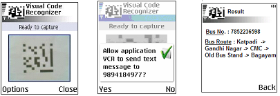 | Figure 8. Snap shots of Recognizer Mobile Application snap |
7. Conclusions
- In this paper we presented an extended application of a visual code system for camera equipped mobile phones. We were able to use visual codes as a link to input the bus number/ bus stop ID number using the camera phone of the mobile device to the mobile application and thus lookup the database for the required bus route information. The recognition algorithm used to recognize visual code takes optimal time to decode the visual code. The algorithm successfully recognizes images of visual codes that are tilted and ill-illuminated. In order to decrease the time consumed in recognizing the visual code we could also send the image to the server and process it there instead of processing it at the mobile device. The problem in this scenario would be the time required to send the image as a Multi Media Message (MMS) to the server.
ACKNOWLEDGEMENTS
- The author would like to thank the Department of Science and Technology (DST), Government of India. This work forms part of the Research and Development activities of the TIFAC-CORE in “Automotive Infotronics” project funded by DST. Javed A. Rahman and Surbhit Jain would like to thank the TIFAC-CORE Centre at VIT University, Vellore for providing the necessary hardware and software facility for carrying out this work successfully.