Manhar L. Shah
MVM Electronics, Inc., 3410 N Harbor City Blvd., Suite E, Melbourne, FL 32935 USA
Correspondence to: Manhar L. Shah, MVM Electronics, Inc., 3410 N Harbor City Blvd., Suite E, Melbourne, FL 32935 USA.
| Email: |  |
Copyright © 2025 The Author(s). Published by Scientific & Academic Publishing.
This work is licensed under the Creative Commons Attribution International License (CC BY).
http://creativecommons.org/licenses/by/4.0/

Abstract
Einstein’s Special Relativity Theory (ESRT) is restricted to the inertial frames being synchronized zero for the position and time at the origin. This author finds several deficiencies in ESRT and its prevailing understanding: (1) approaching traveler’s velocity is not properly envisioned in ESTR and Lorentz Transformation (LT), (2) relatively moving inertial frame is fictitious and only serves to map Time Relation (TR), (3) two real frames need to be synchronized without relative motion for proper space-time comparison, (4) concept of length contraction and out of sync time is for the fictitious comoving frames not for the real frames. The stated deficiencies were found while studying many existing Kinematic (non-inertial) Special Relativity Theories (KSRT), paradoxes and prevailing concepts/consensus of ESRT. Many non-inertial special relativity theories reported in the past were in error due to above stated deficiencies of ESRT. This manuscript explains the above deficiencies and provides better modelling and understanding of KSRT. Previously reported KSRT by this author involving an integral formula was found to show non-physical aspects in some scenarios is revised with a new model. Contrary to the prevailing concept, the dimensions of a real object observed in the stationary frame remain unaltered even after the object gains velocity. Ongoing for almost for a century, erroneous concepts such as length contraction and simultaneous events as well as earlier non-inertial theories and many paradoxes are repudiated.
Keywords:
Special Relativity, Non-inertial Special Relativity, Comoving inertial frames, Accelerated frame, Hyperbolic trajectory, Fermi coordinates, Infinitesimal Lorentz transformation, Twin paradox, Rotating frame, Length contraction
Cite this paper: Manhar L. Shah, Non-Inertial Special Relativity: Debunking Paradoxes and Correcting the Prevailing Erroneous Consensus, International Journal of Theoretical and Mathematical Physics, Vol. 15 No. 2, 2025, pp. 27-38. doi: 10.5923/j.ijtmp.20251502.01.
1. Introduction
Einstein’s Special Relativity Theory (ESRT) seeks to relate position independent time of a reference frame to the time of an observer or traveler and his frame. Interchangeability of two frames and assignment of Out-of-Sync Times (OST) to positions away from the traveler (in his frame) made the situation complicated and resulted in many misunderstandings. Since there cannot be a special traveler each position of the traveler frame can be a synchronizing position making frames associated with two positions incompatible and the traveler’s frame fictitious. Inertial traveler moving away from the stationary origin can be envisioned as receding only. So ESRT covers the subset of the full non-inertial traveler cases. Time dilation was the result of the constant nature of the speed of light and the inertial aspect of the traveler relative to a stationary observer. This manuscript shows for the same condition of constancy of speed of light events occurring at the stationary observer’s position may take longer to reach the traveler if he had reversed the velocity for some time. For the general velocity profile of a traveler, non-inertial special relativity theory, referred here as Kinematic Special Relativity Theory (KSRT), is necessary.This author finds several deficiencies in ESRT and its prevailing understanding: (1) approaching traveler’s velocity is not properly envisioned in ESTR and Lorentz Transformation (LT), (2) relatively moving inertial frame is fictitious and only serves to map Time Relation (TR), (3) two real frames need to be synchronized without relative motion for proper space-time comparison, (4) concept of length contraction and OST is for the fictitious comoving frames not for the real frames. These topics are elaborated in Sec. 2.Comoving Inertial Frames Concept [1-2] (CIFC) is used to extend ESRT to non-inertial case. In CIFC the velocity of the traveler is matched to Comoving Inertial Frame (CIF) without change of his clock time (age) during velocity transitions. Same should be applicable to all positions of traveler’s frame. In that case CIF’s OST cannot match the real time of the traveler’s frame. So the CIF is only fictitious. ESRT is only limited in this respect and needs to be expanded to include the non-inertial condition in a proper manner.Existing CIFC uses only the magnitude of velocity for the Lorentz Contraction Factor (LCF)  and the incremental TR
  This amounts to resynchronizing at every switching instance. Use of only magnitude of velocity and
  is correct for the linear velocity profile without change in velocity direction. The reference sync signal in oppositely moving inertial frames F’1 and F’2 with respect to a stationary frame F are different. Observer switching from F’1 to F’2 will lose the time reference with F’1 so his TR for F’2 cannot be used for F’1. TR in F’2 is with the new location of F and not the original one. The incremental TR with CIF being resynchronized has ESRT’s symmetry so
  is also correct at x=0. That is why in the twin paradox case many publications require an erroneous additional argument to break the symmetry and claim its resolution. With the prevailing CIFC procedure, correct TR is possible between the traveler’s position and the original stationary observer only in the case of linear travel without velocity reversal. Therefore, some non-inertial theories appear fine for limited cases but are in error for the general velocity profiles. Proper understanding of light propagation characteristics in two frames with general velocity profiles is necessary for developing KSRT. KSRT was reported [3-4] earlier by this author after taking into account the above mentioned points and utilizing the new physical model and simultaneity condition. This was done using light propagation path length (time=length/velocity of light, c) for the light signal of an event occurring at the synchronization position in the reference frame being simultaneously detected by the traveler and coincident observer in the stationary frame. The simultaneity condition is natural and central to ESRT. The final result of the KSRT was an integral formula for TR between two frames. Later in some scenarios, inconsistency was noticed in the reported KSRT. Specifically, clocks of two frames continue to increment at different rates for some time after stop. This cannot be accepted in a real physical case. Extensive research provided better physical modelling and revealed the cause. Use of light propagation delay between the final position of traveler and origin instead of the incremental travel procedure caused the issue. A detailed procedure of developing the corrected KSRT using spherical wave-front light is presented in this paper. Sec. 3 details light propagation in two frames in non-inertial cases. KSRT is developed in Sec. 4 using a more intuitive and easier model of Sec. 3.Length contraction concept prevailing over more than a century has generated many paradoxes. Earlier publication [5] by this author shows length contraction doesn’t exist in ESRT. Sec. 5 is devoted to further explaining why the length contraction concept is incorrect. Length of an object gaining relative velocity maps with comoving fictitious inertial frame expanded by
  and observed contracted by the same factor
  in the stationary frame. Clocks in the inertial frame have OST but clocks in the real frame retain time during velocity transition and increment equally at all places, the same as the inertial frame’s clock of the synchronization position. Absence of OST impacts Spatially Separated Simultaneous Events (SSSE) concept of ESRT as discussed in Sec. 5. The next section shows how various paradoxes reported over many decades in the past do not exist or can be resolved with the correct KSRT. This section also points out and explains errors in several existing non-inertial SR theories and concepts/consensus of ESRT. Conclusion follows thereafter.
2. Deficiencies of ESRT
Nomenclatures used in this paper are first explained. An inertial frame F is assumed stationary and forms the reference frame. Another frame F’R is a real frame containing all observers situated at every coordinate position. A fictitious traveling inertial frame F’ co-moves with F’R in each constant velocity segment. Frame F and F’R are synchronized without relative velocity and clocks at every position in both are set at 0. A traveler A’R in F’R, and observer A in F and A’ in F’ are positioned at the coincident origins of all frames. Within infinitesimally short time after F’R gains velocity F’, F’R and F achieves synchronization with all origins coinciding and registering zero time. Coordinates  or
or  for space and t for time is used with subscript/superscript indicating the frame. Synchronization sets
  with all
  . Velocity is indicated by
  or
or  . All illustrations use
  and
and  with
with  unless specified. All variables:
  and
and  are functions of
  Inertial frame condition of ESRT made the description of the theory easy in one dimensional form and ray like light propagation. In reality an atomic clock transmitting the reference time signals in general will have spherical wave-fronts. Time difference will be identical over the entire spherical surfaces of wave-fronts of a given radial difference. KSRT needs to address change in velocity direction as well, so formulation using spherical wave-fronts is necessary.The assertion of ESRT deficiency (1) is explained in Fig. 1. A’ after traveling some time may reverse his velocity. His forward and reverse travel is depicted in Fig. 1 with time pulses from A. Velocity of A’ is such that he travels one time pulse in the duration of two time pulses by A. Fig. 1a is for the forward and Fig. 1b is for reverse travel. It is not possible to envision travel of A’ in opposite direction to the reference wave-front propagation direction in ESRT and LT because the initial velocity can only be in the outward radial direction. A large difference in light propagation path lengths in receding and approaching cases can be seen in Fig. 1a and Fig. 1b, respectively. Prior theories and CIFC reversed the synchronizing pulse propagation direction for the approaching cases and used the same receding value for the light propagation path length in approaching cases. (Note that in Fig. 1b A’ will be receding after it passes A) Fig. 1c further depicts the difference between receding and approaching case for the correct incremental TR. In CIFC
  is used to obtain the incremental TR
  Fig. 1c shows
  and
and  are discontinuous but
  and
and  are continuous. Discontinuity implies loss of synchronization of time. The correct procedure should use
 | Figure 1. Approaching condition not envisioned in ESRT and LT. TR should use wave-fronts (a) 1-3 in receding and (b) 1-5 in approaching. (c) Comparison of light propagation path length in CIFC for velocity reversal: wrong  |
The current CIFC case with  can be shown in error using the Doppler Effect for the approaching case. If A’ after moving far from A changes velocity direction by 90 degrees then
  will be the same according to this manuscript. Doppler shift will be absent in that case except due to gravitational effect. The current CIFC will show continued time dilation and hence downshift (Doppler Effect). In general case A’ moving in a circle without external force acting upon it around A would not have time dilation because the outgoing spherical wave-fronts in both frames will coincide due to no radial velocity. As discussed in Sec. 3 in connection with the light propagation in two frames a significant aspect of TR for the approaching traveler is uncovered. This aspect has not been recognized in the past due to the restriction of ESRT and LT to the inertial frames. This novel aspect and use of local incremental TR made significant impact on the development, understanding and modification of previously reported KSRT. For a given
  and
and  the sync reference light propagation path length and hence the TR is not the same for the approaching and receding velocity. This also impacts LT and requires different STR for approaching and receding velocity segments.As for the other deficiencies, suppose multiple observers in F’R gain the same velocity at t=0 in their own clock. Clocks cannot jump, so in F and F’R all clocks will have the same time as t=t’R=0. Clocks and origins in F’ and F t=t’=0 and x=x’=0 matches as synchronization. Since there cannot be a special observer, each observer in F’R can consider himself as the origin. If F’ and F’R are identical then with t=0 it is not possible to have t’R=0 over the entire F’R and F because in F’ time varies with position (OST). This implies F’ and F’R cannot be the same and F’ needs to be fictitious with only equal time for A’ and A’R. Time at x’≠0 will be fictitious so that the spatial positions of F’ identically match to F’R.No special observer implies each position in F’R can have its own sync pulse and time increment will be identical. It should be noted that LT also has identical time increments at all positions in F’ as a function of t. Instead of using separate sync pulses for each position in F’R it is better to think that all positions in F’R have the same time as A’R. The fictitious frame simply adjusts to spatially match the real object (frame) so the spatial relation between the stationary and traveling real frame is identical to the Galilean transformation and not according to the Boost matrix. This topic is further elaborated in connection with the Thomas Precession. Verification of the current concept of length contraction, as a moving rod in F’ (co-moving with F’R) along the velocity direction is physically shorter in F, is only possible with the rod coming to rest in F and found to be longer. But the rigid body concept is used to explain that a rod will be stressed and collapse to the observed length in F. In the opposite way, a rod in F can be made to gain velocity and observed contracted in F to fulfill the length contraction concept. No such experiment exists yet. Alternately the same rigid body concept would allow the rod to stretch in F’ and be observed of the same length in F. A logical step would be to reject length contraction in ESRT and designate F’ as the fictitious frame. A graphical illustration is provided in Sec. 5 to further enhance this explanation. Analysis provided in this paragraph makes clear the need to synchronize F’R and F without relative velocity and modify the length contraction concept/consensus.Although OST is present for the fictitious frame it is absent in F’R and it is the same as the origin (same as A’R) independent of position in F’R. The SSSE concept is affected as a result no OST. Section 5 elaborates on SSSE concept showing it holds only for observer positions between event locations. Debunking paradoxes and correcting the prevailing erroneous concepts/consensus is taken up in section 6 following conclusion in section 7.
3. Light Propagation in Two Frames
Constancy of the speed of light and common path of light propagation in F, F’ and F’R is the essence of ESRT. TR between two frames is obtained by dividing propagation path length in each with c. In the real physical case synchronization should be with spherical wave-fronts and not with plain waves as in ESRT and LT. Spatial and time difference between two spherical wave-fronts are related by  so the discussion on light propagation is important. As explained in Sec. 2 time over an entire real frame is the same as the synchronization position. The inertial frame comoving with the traveler is synchronized with velocity so there are OST terms associated with it. For this reason only the TR between A and A’R is discussed here. The initial constant velocity period of the traveler is considered first so A’R, F’R and t’R is the same as A’, F’ and t’, respectively.
 | Figure 2. The spherical wave-front light used for TR in ESRT. Approaching condition doesn’t arise due to inertial frames in ESRT but in non-inertial case A’ can have negative radial velocity |
The spherical wave-fronts transmitted from the origin in F (observer A) are as shown at time t in Fig. 2. R1 having radius ct is the reference wave-front generated at A at t=0. Other wave-fronts are: R2 having radius vt at the position of traveler; R3 having radius v(vt)/c=v2t/c, the distance frame F’ would have traveled during light propagation from A to the position of A’ at time t and R4 at the start radial distance of A’ (0 for ESRT, so not shown). The quantity, v(vt)/c represents the distance moved by F’ towards the reference wave-front R1 in time light travels from A to A’. In this case it will subtract from ct for the mapping. In the non-inertial case when v is the approaching velocity the term v(vt)/c is the distance moved away from R1 and v(vt)/c will add to ct as discussed later.The main point of Fig. 2 is to show how the radial difference between R3 and R4 enters in determining t’. Movement of A’R. towards the reference wave-front generated at t=0 in F is the same as movement away (receding) from A (origin). A’R can only have receding movement in ESRT. A non-inertial A’R can have approaching movement (toward A) or opposite from the reference wave-front expansion after he has traveled some distance first.As discussed in the previous paragraph LT in connection with ESRT only has the receding condition so  is subtracted from
  In explaining paradoxes, concepts/consensus and developing non-inertial theories the same was continued in the past. Travel from point to point only appears receding with a spherical wave-front starting at every new location but there is no connection to the original reference wave-front generated at t=0.Whether point to point receding model is correct or approaching case needed in KSRT is settled with physical reasoning discussed later. In non-inertial case, if approaching velocity is not encountered then
  can be successively applied without any error for linear trajectories. If approaching velocity occurs then
  needs to be added to ct as explained before and the incremental
 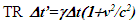 needs to be used. Well-known LT formula are reproduced below with addition of approaching condition,
 | (1) |
 | (2) |
 | (3) |
 | (4) |
with F as the stationary reference frame. Eq. 1 and 2 are discarded because t is independent of x’. In fact LT should not have used Eqs. 1 and 2 but should have stipulated that F is the reference frame with the same time at all positions in F. The current concept of F and F’ being equivalent is wrong. If the reference frame is changed as FàF’ then the true length L in F doesn’t transform to  , instead according to Eq. 3 it should be
  Eq. 4 has ± sign to account for the receding - and approaching + case. The incremental form of Eq. 4 is,
 | (5) |
All past derivations of LT can be shown to allow ± sign in Eq. 4 and 5 and still confirm Galilean transformation for small v. Only – sign became established in ESRT for Eq. 5 due to inertial frames. It is perplexing why the result of the approaching case had never been used in extending ESRT to the non-inertial case in the past. Going back to one derivation of LT by the well acclaimed author- Moller [6], it is possible to arrive at the result  for the approaching case in LT. On page 40 Eq. 22 has
 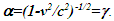 It is derived as the square-root of the term. In that case it can have ± sign. Substitution of it in Eq. 17 on page 39 provides
  or
or  Both expressions of t’ for small v are in confirmation to the Galilean transformation.Need of + sign and determination of the correctness of point to point receding or the approaching case model can be found with physical reasoning using a scenario with light propagating normal to the velocity direction y axis. Such a scenario was presented in connection with the twin paradox [7]. Using the same scenario let A’ travel at velocity v=c in F for time T/2 in each direction. With the prevailing concept (point to point receding and
  time of A’ upon return will be zero and no light propagation can be expected over y’ in F’. However, light would have propagated cT distance along y which coincides with y’. This outcome violates ESRT itself.If the approaching case of Eq. 5 is used then time of A’ upon return will be
  . Light ray would have travelled in F’ distance
  and back in the x’ direction and cT in y‘ direction. Light propagation distance in coinciding axis y and y’ is same and equal to cT as it should be.
  time of A’ correctly accounts for
  light propagation path length in x’ direction. This scenario shows + sign for the approaching case is necessary.In a non-inertial case A’R can reverse/change velocity direction after some time from t=0. Reverse velocity will make A’R move opposite to the reference wave-front expansion direction Then during the light propagation time
  A’ and A’R will move away from the reference wave-front. This causes light propagation path length increase in F by
  over
over  Then the differential TR becomes
 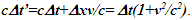 In general case,
 | (6) |
can be used for linear travel with v positive when it is along the reference wave-front propagation direction. It should be noted that the relation for the approaching case in Eq. 6 is limited to the arrival of A’ back to the origin. To gain more insight, Eq. 6 is written for the approaching case as 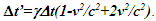 Now it is easy to understand that instead of gaining time
  for receding time is lost for approaching so doubling the influence.
4. Non-inertial SR: KSRT
Non-inertial Special Relativity Theory or KSRT is detailed in this section. Procedure to obtain TR with the traveler’s trajectory as velocity  is discussed in Sec. 4.1. For velocity
  (here t’ same as t’R) TR is obtained using the procedure of Sec. 4.2. The trajectory of A’R in general will be in three dimensions. A two dimensional depiction is sufficient for the relevant information and results for a three dimensional case. Synchronization with real object or frame F’R that will be moving with F’ is done in KSRT when there is no relative velocity between F and F’R, meaning
 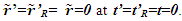 In this case the observed clock times of F’ in F won’t agree with ESRT except at the origin. As shown earlier only TR of A’R in F is necessary because all positions in F’R have the same time and are observed same in F.Following conditions are used in developing the KSRT:(a) F’ is a fictitious frame comoving with a real frame F’R. Each position in F’R is considered to carry its own F’ with a coinciding position in F as the synchronizing position as such. Light propagation path length in F and F’ are related as
  where u is the radial distance from A in F and
 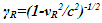 and vR is the radial velocity. (b) F’R is associated with the traveler A’R. Time t’R in F’R is independent of position and observed the same at all positions in F equal to at the origin of F’R (same as A’R). The spatial relation of F’R observed in F is identical to the classical or Galilean relation.(c) Time at all positions of F’R is preserved and observed unaltered in F at the instance of traveler’s velocity transition.(d) Velocity is positive when the projection of the velocity vector is in the direction of the reference sync wave-front propagation direction.
4.1. KSRT: Trajectory in the Stationary Frame
Fig. 3 graphically shows various items in F for non-inertial cases. Observer A and A’R are shown at some time t after synchronization and depicted by cross. All wave-fronts from R1 to R4 are shown according to previously stated parameters. The time at which R2 was originated is not important. Also shown are the wave-fronts in F and F’ generated at the position of A’R in F at time  and propagated over the infinitesimal time interval
  Fig. 3(a) is for the receding and Fig. 3(b) is for the approaching velocity segment, respectively. In both cases the wave-fronts between rays
  and
and  propagate distance
  radially outward while A’R moves
  Light propagation distance in F’ during the travel of A’ for
  in F is used to find
  Light propagation time over the travel path of A’ in
  and during this time A’ moves
  in the radial direction and light propagation path length in F’ measured in F for
  is decreased or increased by this amount
  over
over  for the receding or approaching case, respectively.
  is the radial velocity given as,
 | (7) |
The radial distance between R1 and R3 as depicted in Fig. 3a and 3b is this combined light propagation path length in two cases. In one dimensional case A’R will move along the horizontal axis and  Spherical wave-fronts are used to properly show the light path length. The receding or approaching condition is determined from the vectors in the stationary frame connecting the origin to the traveler’s position at the start and the end of the incremental period. One dimensional case is considered first. At a given time t the traveler will be at a distance x(t),
 | (8) |
 | Figure 3. Spherical wave light propagation depiction in stationary frame F for (a) receding and (b) approaching velocity of traveler. Primed (‘ ) items not to scale |
For receding traveler segment the quantity  is,
is, | (9) |
is positive. For the approaching segment the same quantity  will be negative. The incremental time relation is obtained as outlined in Sec. 2. For light propagation over distance
  frame F’R and traveler A’R moves
  and represents time
  For receding case the mapped value of light travel length in F must be decreased from
  to
to  Corresponding TR becomes,
 | (10) |
On the other hand, negative  for the approaching case causes F’R and A’R to move backward from the reference wave-front. This requires
  to be added to
  So the TR becomes,
 | (11) |
Integration of Eq. 10 and Eq. 11 can be combined to provides TR between two frames with the sign of v positive when it is along the reference wave-front propagation direction, | (12) |
Integration of Eq. 12 in the twin paradox case shows  So the traveling twin’s age T’ is older by a factor
  than the stay home twin’s age T. Same result was reported by this author in several earlier publications. This result is opposite to many published explanations over a century predicting traveling twin younger as
  Sec. 5.1.1 points out errors in the well-established prevailing conclusion of the twin paradox. It is possible that general relativity may amend the result but from the purely kinematic consideration the traveling twin will be older upon return.Three dimensional cases follow similar procedure to the one dimensional case. Traveler’s journey is now in vector form. Traveler’s position
  at time t will be,
  | (13) |
For receding or approaching segment of travel the quantity  as shown in Fig. 3 is,
 | (14) |
In the receding case the light path length in F’R mapped in F is  while in the approaching case it is
  So in the general case the infinitesimal light path length mapping as shown below can be used,
 | (15) |
where 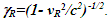 Integration of Eq. 15 over the total trajectory and dividing both sides by c will yield the TR between two frames as,
 | (16) |
Steps involved for computing Eq. 16 suggests numerical computation will be necessary except for the linear travel. For linear travel without reversing velocity Eq. 16 becomes, | (17) |
In ESRT v is constant so Eq. 17 will yield  the standard time dilation of ESRT.
4.2. KSRT: Trajectory in the Traveling Frame
This section provides a procedure for obtaining the TR between an observer in the stationary (inertial) frame F and a traveler in a non-inertial frame F’R when the trajectory is specified in the traveler’s time. There are two ways to specify the traveler’s velocity: (i) with respect to the rest frame F as  or (ii) as instantaneous velocity gain
  in current CIF as it would be for the rocket burn. Data with velocity steps and time intervals can be converted to the required form using standard velocity addition of ESRT. The procedure outlined here is for the data in form as (i). If data as in form (ii) are given then velocity in CIF need to be transformed to F. The procedure to obtain TR for a general velocity profile appears quite complicated with data in t’ so only the linear velocity profile is considered here. Velocity in CIF is
  Transformation of
  and
and  in F without length contraction is
  and
and  where
where  is the denominator. So the velocity
  in F after change is
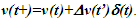 If
If  is positive then we get
  Conversion of the velocity profile with this procedure allows use of Sec. 4.1 to obtain TR.
5. Length Contraction, Out-of-Sync Time and Simultaneous Events
For consideration of the length contraction concept [8] let a rod of length L’R and L in F’R and F, respectively has  when there is no relative velocity. The length contraction concept of ESRT assumes L’R will be of the same length in comoving F’ when it gains velocity. It will be observed to be real contracted in F with length
  When the rod is brought to rest in F, its length will be the same as
  with non-rigid body concept. Such a concept cannot be taken seriously. Instead it is better to map the rod’s length L to length
  in F’ fictitiously and be observed real and the same as L in F. This means the observed rod’s length is not affected by its relative velocity. Expansion of rod’s length in F’ is necessary for mapping the TR. It is like observing images on a strip projected with a magnifying lens and observed with a de-magnifying lens with a 1:1 ratio.How can two spatially separated clocks in a stationary frame when they gain velocity at the same time (as an example t=0) show different time in the stationary frame? Time (clock) jumping due to velocity gain appears non-physical. That inquiry led to the realization that there is no real length contraction or expansion of length in ESRT. The prevailing length contraction concept in SR has generated many paradoxes. A previous publication of this author shows length contraction is not real. Fig. 4 graphically shows in detail how a real object’s length gets mapped expanded in a comoving fictitious inertial frame and appears contracted to its original length at rest in the stationary frame. This depiction is in relation to the prevailing concept of trapping a train in a shorter tunnel. If this scenario is observed in reverse, meaning the train speeding from rest, it is easy to see train mapping to the expanded length to the comoving inertial frame. The error lies in assuming that the moving train’s proper length is larger than the tunnel. Then further arguing, at closing of the gates train’s ends will have different times and the train will collapse as a non-rigid body and fit inside the shorter tunnel. Such assertion is in error. The reverse process provides the correct visual picture. In that, a stationary train is inside a tunnel of equal length. Whole train can be assumed to gain velocity at t=0 with thrusters all over the length of the train. As depicted in Fig. 4 the length of the train in the comoving fictitious inertial frame F’ will map to
  times the proper length of the train. Each part of the train will retain clock time and coincide with the part in F’ having OST. One can consider the train is expanded in F’ or another way the length contraction of F’ being observed in F matches the train’s length in F. Then the train can co-move with F’ without any length change. This is backward from stopping the train in a shorter tunnel. The expanded train appears contracted to the same length as the tunnel in the stationary frame.
 | Figure 4. (a) Length contraction concept assumes a long train in F’ being shorter in F so fits in a shorter tunnel. (b) So as the tunnel is closed train collapses with various parts coming to rests at various times t’ in F’ at t=0 in F. Conversely as the train speeds various parts can speed at various times t’ in F’ with t=0 in F and virtually expand it in F’, but that is ignored in the concept |
The explanation of paradox designed by E. Dewan and M. Beran [9] in 1959 and became more widely known as Bell’s Paradox when J. S. Bell modified it [10] shows some agreement to absence of length contraction in ESRT. Discussion on this paradox argues that the separation distance of two spatially separated spaceships when they gain equal velocity at the same time remains same as in the stationary frame. This is in conformity with this paper. The remaining arguments are based upon accepting the comoving inertial frames as real rather than fictitious and theory not related to SR. Of course, the synchronization in the fictitious frames is associated with the length contraction, but it is just the mapping. The actual object’s dimensions neither change nor observed change due to relative velocity.OST of ESRT is associated with F’. Time of any position of real frame F’R is observed same in F. However, the clocks in F’R will advance identically to the clock of A’ and will be equal to TR obtained using Eq. 14 as 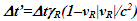 after dividing it by c.Because all clocks in F’R retain time with velocity transition and increment equally with respect to t there is no OST in F’R. Even in F’, OST can be eliminated if clocks were set by subtracting time
  at each position x’ in F’. The OST is artificial because time increments equally with increment of t at all positions in F’.Without OST SSSE will be observed simultaneously in all real frames regardless of the relative velocity except when the observer position is between event locations. This exception is due to light or information propagation taking place in two opposing directions and is further explained in Fig. 5. A scenario in which flashes of light occurs simultaneously at spatially separated places Q1 and Q2 in F and observed at the mid-point B in F and a coincident observer A’R in F’R. For A’R light from Q1 propagates from left to right but from Q2 it propagates right to left. Sync reference wav-front can only propagate in one direction so this situation requires two different moving frames. A’R is a common moving observer so for his proper time at Q’1 and Q’2 needs to be different when simultaneous flashes occur in F at Q1 and Q2. Since there are two moving frames, the time difference between Q’1 and Q’2 is allowed. As A’R moves from A to B in F his incremental time for left side frame will be
  while for the right side frame it will be
  according to KSRT presented here, where
  The time difference between Q’1 and Q’2 will be
  same as it would be in ESRT.
 | Figure 5. Spatially separated simultaneous events concept for at the midpoint. For light propagation left to right  For light propagation right to left For light propagation right to left 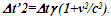 So to have a single value So to have a single value  for A’R at B, time at Q’2 needs to be for A’R at B, time at Q’2 needs to be  from time at Q’1 from time at Q’1 |
If the observation point is outside the region between Q1 and Q2 two reference sync wave-fronts are not required and SSSE will be observed simultaneously in both F and F’R frames. This can be proven by selecting Q1-Q’1 as the synchronization position in Fig. 5 and finding time t’ in F’ at Q’2 when flash from Q1 reaches Q’2. ESRT shows  and represents distance
  in F’ and it is equal to
  in F’R according to KSRT presented here. Thus events are observed simultaneously in F’R as well.
6. Paradoxes and Erroneous Theories Conceptions/ Consensus
Several theories, conceptions/consensus and paradoxes persisting for a long time and attributed to ESRT are found to be in error based upon KSRT presented here. Only the kinematic effect is considered for the investigation. In some cases the results of erroneous non-inertial SR theories may agree with the experimental data that would have resulted when General Relativity or curved space is considered. Such agreement has been used to justify the correctness of an otherwise erroneous item. Muon lifetime in the CERN experiment is one of these items. The CERN experiment is discussed in the last subsection to show how the dynamic effect is misinterpreted as the ESRT effect.
6.1. Paradoxes
6.1.1. Twin Paradox
Many explanations showing the traveling twin younger exists in the literature and on the internet [11-12]. In one scenario F is the reference frame. The traveling twin A’ in frame F’ travels to a far destination B from the stationary twin A (A and B are both in F). Another frame F” with A” at the origin and an observer B” at a position to receive time data from A’ (or equivalently A’ switching from F’ to F”) travels in the opposite direction. B” reveals the time to A when they cross. A’ will correctly transfer time 0.5 to B” when A’ is at B. It is argued that B” is moving in F so the incremental time should be 0.5 for B”. On the surface it appears correct. Error occurs due to not recognizing the counter propagation of the synchronizing signal in F’ and F” with F as the reference frame. For the synchronizing signal propagation direction of F” 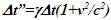 must be used. In that case traveling twins will be older. Besides A would claim B” must have seen A’ at B when A recorded time 2 in F”. Further if A’ had switched the frame at the position of B he would have met A with time in F” as 4 while his time would be 2. So A’ is older and no resolution of the paradox.The approaching case also has ramifications on the discussion provided in Moller’s book referenced in 6. The discussion on (98) clock paradox on page 258 is in errors. Eq. 153 on page 259
  is assumed the same for the receding and approaching case. That is not true according to KSRT.
  needs to have separate
  and
and  for receding and approaching values, respectively. That will impact Eq. 159 on page 260. Eq. 161 on the same page will become,
 Eq. 166 on page 261 is wrong because C2 in S2 is stationary and C1 is moving. Results of the book from previous pages would make
  and
and  equal to
  and
and  respectively, in Eq. 168 on page 261. Then
  will result. Other published scenarios justifying traveling twin younger are in existence for many decades. A very convincing one uses Doppler shift [13] providing time reference. This explanation uses Doppler shift formula Eq. 5-15 on page 137 as
 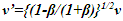 for the receding traveler. Let
  travel time 1 in F for each direction and
  pulse per proper unit time in F. For travel time 1 in stationary frame F, traveler A’R will encounter
 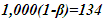 pulses and with Doppler shift equals time 0.5. The remaining 1,866 pulses will be observed upshifted by A’R as he reverses his velocity. Application of Doppler upshift provides time 0.5 totalling time 1 for A’R and 2 for the stationary twin’s time. That means the traveling twin is younger. This sounds very convincing and difficult to dispute even with a considerable amount of thinking.The error is due to the assumption that even with approaching conditions during the return journey of the twin, ESRT time dilation is valid. This is equivalent to CIFC point to point receding case. The correct relativistic Doppler upshift for the approaching case following the same procedure as in reference 13 should be
 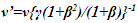 when Eq. 6 is used. Those 1,866 pulses during A’R return journey equals time 3.5 for A’R with the correct formula. That makes the traveling twin’s time 4 and him older.With spherical waves an observer can use sync wave-front in + or – direction. That allows an explanation for true TR in dual form. Besides the approaching condition explained in the previous paragraph, the same error can be explained in a different way. Assumption of 866 down shifted pulses of outbound journey suddenly turning into upshift at the moment the traveling twin reverses velocity is wrong. Constancy of speed of light requires those pulses remain downshifted for the traveling twin even with velocity reversal otherwise A would suddenly appear closer to A’R. Then these 866 downshifted pulses will amount to time 3.2313. 1000 pulses of the inbound will be upshifted and amount to time 0.2679. Total incremental time for the inbound travel will be 3.5 as before.An animation [14] showing traveling twin younger using Doppler Effect is also in error. This animation assumes TR for the inbound travel of the twin same as the outbound. As a result fewer birthday signals are generated with wrong time dilation TR. The situation is similar to the Doppler Effect considered in the previous paragraph.A question arises for the time dilation of muon. To a ground based observer approaching muons Doppler shift would seem to appear upshift and time contraction for muon. As stated earlier there is no special observer so with no reversing velocity muon can consider itself as the synchronizing entity and would be receding in F. Alternatively muon can use the same TR as of any synchronizing position producing time dilation. Similar condition applies to any position away from A’R in F when no velocity reversal occurs and only time dilation
  results. Then either downshift with 134 pulses or upshift with 1,866 pulses and Doppler Effect as in referenced in 13 will give
  time in either case.The Doppler shift difference in approaching case and muon case is further explained. If muon is approaching A from distance vt then oncoming pulses cannot be considered Doppler down shifted. There is no difference between upshift observed in the twin inbound journey and muon’s approach to A. The apparent upshift incremental time 3.5 for muon for time 1 in F needs explanation. In this case the synchronization position is at A so the time of muon at the distance L=|vt| is not 0 but it is
  as v is negative because sync pulse propagation is directed towards muon. That means muon is not created for time 3 at that position and when it arrives at A its time will be 3.5-3=0.5 same as the receding case. At t=1 muon passes A. Then v as well as
  will be negative and
  will prevail.Another explanation uses the word lines as described on pages 156-157 in French’s book referenced in 13. New word line is drawn at the return location as if synchronization occurred there. That is in error. To use the return point as a new synchronization origin for the forward journey the word line needs to be shifted making
  In this diagram no specific condition of the traveling twin changing velocity is used. A similar word lines diagram in F’ frame and Eq. 5-28 would produce
  instead of
  and the paradox won’t be resolved.
6.1.2. Trapping a Train in a Shorter Tunnel
This concept is already discussed in Sec. 5.
6.1.3. Ehrenfest Paradox
This paradox arises from the length contraction idea. Without real length contraction mathematical relation, circumference =  radius will not be violated and this will not be a paradox.
6.1.4. Force between a Moving Charge and Current Carrying Wires Due to Length Contraction
This concept is based upon the idea that an outside electron comoving with current electrons in wire will see the spacing between positive ions decreased [15,16]. That would create excess positive charge in the wire and create a force between the wire and the outside electron. The explanation also states that the linear separation/density of electrons with length contracted must be adjusting to positive ion separation because electrical force has not been observed in the lab from a current carrying wire. This explanation agrees with fictitious expansion and contraction of length with relative velocity. With differing clock rates for moving electrons and stationary positive ions due to time dilation, linear separation/density in two frames would be different. With  and equal + and - charge density of positive ion charge N in F will be observed as
  in F’R by the test charge. This creates net positive charge for the wire in F’R and attractive force on the test electrons. Thus time dilation can provide the same results as length contraction to arrive at the same conclusion. Because electrons do not form rigid frames this concept doesn’t provide a definitive answer to length contraction. Fig. 6 shows how positive ions will appear in F’R (electron’s frame) to spend more time between their spacing and result in excess positive charge to have attractive force.
 | Figure 6. Test charge seeing positive ions spending more time between electron spacing |
6.1.5. Minkowski Metric
The Minkowski metric is reproduced below, | (18) |
In this matric  is the proper time, meaning in this particular case the time in the clock of an inertial traveler. Many publications over a long history have used
  as the proper time of the traveler even with non-constant velocity. As discussed earlier, Eq. 18 is applicable for linear non-reversing velocity travel. This metric (as a point to point receding process) when used in other velocity profiles will generate erroneous TR.
6.1.6. Concept of Rigid Body
Again this concept arises from the idea of length contraction. A rigid body is not achievable due to mechanical reasons but conceptually it can be envisioned if there is no real length contraction. ESRT with real length contraction would preclude even a virtual rigid body concept. A stationary body with distributed thrusters over its entire length and clocks synchronized to time t=0 at all positions can fire all thrusters at t=0. No change in length of this body will be observed in both classical and ESRT condition. If the body has very high rigidity then even a single thruster can have the same outcome, almost mimicking a rigid body.
6.1.7. Lorentz or Frame Boost
Lorentz or frame Boost is due to the concept of length contraction in ESRT. The concept hypothesizes that the actual (proper) length of a relatively moving ruler or a coordinate axis scale (parallel to v) in F’ is larger by a factor  than observed in F. If the ruler changes velocity its proper length as assumed in F’ will change in F according to LT. If the velocity of the ruler changes direction then the ruler will appear rotated. This paper shows the proper length of the ruler or the coordinate axes scale remains unaltered in F due to velocity gain. The fictitious frame F’ adjusts itself to match the real frame as velocity changes. Absence of length contraction makes the Boost concept unnecessary.
6.1.8. Thomas Precession
This notion hypothesizes that a coordinate system is rotated when velocity direction changes similar to the Boost. This notion arises from the ESRT length contraction idea. Absence of length contraction makes the coordinate system appear to maintain the same angular orientation with any change in the direction of velocity. Thomas precession is a kinematic effect in the flat spacetime of special relativity. Only the kinematic effect is addressed for the erroneous concept. Thomas precession only occurs in curvilinear motion and therefore cannot be observed independent of some external force causing the curvilinear motion such as that caused by an electromagnetic field, a gravitational field or a mechanical force. Experimental determination of this concept is not possible without accompanying dynamical effects making the concept doubtful.
6.1.9. Bell's Spaceship Paradox
This paradox designed by E. Dewan and M. Beran and more widely known as Bell’s Paradox was mentioned earlier in Sec. 4. Explanation provided by Bell and later by Dewan and Beran partially agrees with the present manuscript asserting no change in the separation between spaceships in question. However, the stated length contraction of the string due to ESRT is in error in light of Sec, 4. If the string survives the accelerating stress of classical mechanics its length will be the same as the original stationary value even when moving with the spaceships. Additional relativistic electromagnetism discussion in the article seems superficial. There may be some other non-relativistic mechanical considerations for the detail behaviour of the string and spaceships in acquiring high velocity but that won’t be a part of ESRT.
6.1.10. Muon Lifetime in CERN Experiment
Precise measurement of muon’s lifetime in CERN experiment [16] is reported to show  Many publications by researchers as well as novices proclaimed this as a confirmation of the prevailing traveling twin younger concept of twin paradox. A close examination of the experiment proves otherwise.In order to keep the muons in the ring, electro-magnetic force is necessary. With the origin at the center of the circular ring for F and F’R there is no receding or approaching case. Muons in the circular ring have no velocity component parallel to
  so
so  for the kinematic contribution as evident from KSRT in Sec. 4. The accelerating force on muons in the ring is balanced by the electromagnetic force which can be regarded as gravitational force. Without actual gravity the circular motion of muons cannot be considered free fall (weightlessness). The equivalence of acceleration and gravity principle provides time dilation as predicted by general relativity. The gravitational contribution is
  The measured result is in exact agreement with the gravitational contribution. This explanation also suggests the traveling twin older will be more pronounced in linear travel and may reverse as it changes to circular motion requiring constant acceleration.
6.2. Erroneous Non-Inertial SR Theories
Prevailing non-inertial SR theories [17-23] are found to contain error as a result of utilization of wrong concept such as: accepting length contraction as real; comoving inertial frame same as real object (frame); approaching motion same as receding and simply using  The procedure used in those theories comprise of: (i). simply integration of
  (ii) Fermi-Walker transport with triad and tensors, (iii) non-local Dirac equation, (iv) Lorentz boost, (v) successive Lorentz transformations, etc. In limited cases with liner trajectory without velocity reversal and TR limited at the traveler’s position, non-inertial SR theories as mentioned produce correct result. In scenarios requiring TR away from the traveler’s position such as in twin paradox the results are erroneous. This can be easily understood for
  with velocity reversal at
  For v magnitude positive, time at the position of x at t=0 is
  and with the velocity reversal it becomes
  according to LT. This also shows the Minkowski diagrams have limited application and in error when dealing with general velocity trajectories.
7. Comparison of ESRT and KSRT
As such the ESRT is the subset of KSRT for the time dilation but no length contraction with KSRT as presented here. For linear non-reversing velocity profiles such as for hyperbolic motion both theories would provide same time dilation. Other velocity profiles such as twin paradox would produce significantly different time relations between frames. Even for non-reversing angular change of the velocity direction the prevailing ESRT application will produce larger time dilation than KSRT.
8. Conclusions
KSRT, named for non-inertial special relativity theory applicable to real frames or objects in three dimensional travel cases is presented in this paper. The approaching travel condition and the associated TR is not envisioned in ESRT but it is necessary for the correct KSRT. The traveling inertial frame in ESRT is shown to be fictitious serving mapping purpose for STR. Many paradoxes are shown not to exist and long held conceptions such as length contraction, OST, etc. are repudiated.
References
| [1] | Misner, Thorne, Wheeler: Gravitation, (W.H.Freeman and Co., 1973), Pp 164-166. |
| [2] | A. Drory, Am. J. Phys. 87, 5–9 (2019) doi:10.1119/1.5082535. |
| [3] | M. L. Shah, Int. J. Theor. Math. Phys. 13(4), 85-91 (2023) doi:10.5923/j.ijtmp.20231304.01. |
| [4] | M. L. Shah, Int. J. Theor. Math. Phys. 11(2), 61-66 (2021) doi:10.5923/j.ijtmp.20211102.01. |
| [5] | M. L. Shah, Int. J. Theor. Math. Phys.; 12(2), 25-31 (2022) doi:10.5923/j.ijtmp.20221202.01. |
| [6] | C. Moller, The theory of relativity, 2nd Edn. (Oxford University press, 1972). |
| [7] | M. L. Shah, Int. J. Theor. Math. Phys. 9(2), 55-61 (2019) doi:10.5923/j.ijtmp.20190902.06. |
| [8] | G. F. FitzGerald, Science, 13(328), 390 (1889) doi:10.1126/science.ns-13.328.390. |
| [9] | E. Dewan, M. Beran, Am. J. Phys. 27, 517–518 (1959) http://dx.doi.org/10.1119/1.1996214. |
| [10] | J. S. Bell, Prog. Sc. Cul. 1(2), 1–13 (1976) http://philpapers.org/rec/BELHTT. |
| [11] | R. L. Shuler Jr., J. Mod. Phys. 5, 1062-1078 (2014) http://www.dx.doi.org/10.4236/jmp.2014.512108. |
| [12] | Ø. Grøn, Eur. J. Phys. 27, 885–889 (2006) doi:10.1088/0143-0807/27/4/019. |
| [13] | A. P. French, Special Relativity, New York: W. W. Norton & Company, pp 74-75, (1968). |
| [14] | M. Belloni, W. Christian, A. J. Cox, Exploring the Twin Paradox Using the Doppler Effect, (Am. Asso. Phys.Teach.) https://www.compadre.org/PQP/special-relativity/section3_6.cfm. |
| [15] | R. G. Piccioni, Phys. Teach. 45, 152–156 (2007) DOI: 10.1119/1.2709673. |
| [16] | H. Bailey, K. Borer, F. Comble, H. Drumm, F. Krienen, F. Lange, E. Picasso, W. V. Ruden, J. M. Farley F, J. H. Field, W. Flegel, P. M. Hattersley, Nature. 268, 301–305 (1977). doi:10.1038/268301a0. S2CID 4173884. |
| [17] | R. A. Nelson, J. Math. Phys. 28, 2379 (1987) https://doi.org/10.1063/1.527774. |
| [18] | B. Mashhoon, Phys. Rev. A 75, 042112 (2007) https://doi.org/10.1103/PhysRevA.75.042112. |
| [19] | Y. Friedman, T. Scarr, Phys. Scripta, 87(5), 055004 (2013) DOI 10.1088/0031-8949/87/05/055004. |
| [20] | R. A. Nelson, J. Math. Phys. 28(10), 2379–2383 (1987) https://doi.org/10.1063/1.527774. |
| [21] | W. Rindler, Relativity, Special, General and Cosmology, (Oxford University Press. 2001). |
| [22] | R. A Freedman, H. D. Young, 14th Edn. (University Physics, Pearson. 2016). |
| [23] | D. F Lawden, Introduction to Tensor Calculus, Relativity and Cosmology, (John Wiley & Sons. 1975). |

 Abstract
 Reference
 Full-Text PDF
 Full-text HTML