Charles Uzoanya Ndujiuba , Samuel Ndueso John
Electrical & Information Engineering, Covenant University, Ota, Nigeria
Correspondence to: Charles Uzoanya Ndujiuba , Electrical & Information Engineering, Covenant University, Ota, Nigeria.
| Email: |  |
Copyright © 2015 Scientific & Academic Publishing. All Rights Reserved.
Abstract
Optical nonlinearities play a major role in optical fibre with respect to transmission capacity and performance of the system. This degrades the system performance, especially in wavelength division multiplexing (WDM) systems, where several channels co-exist in the same fibre and propagating simultaneously, resulting in high optical intensities. They can result in pulse distortion referred to as self phase modulation (SPM), cross phase modulation (XPM), crosstalk between channels, and four wave mixing (FWM). However, these non-linearities also have many useful applications, especially for the implementation of all-optical functionalities in optical networks. In this paper, we briefly review the different kinds of optical nonlinearities encountered in fibres, identify the essential materials and fibre parameters that determine them. The paper simulates two channel WDM optical communication systems in single mode fibre over long haul of 100 km to investigate the effect of SPM, XPM and FWM. Their thresholds, managements and applications are also discussed; and comparative study of these effects is presented.
Keywords:
Optical communications, Optical fibres, Optical communication link, Optical nonlinearities
Cite this paper: Charles Uzoanya Ndujiuba , Samuel Ndueso John , Analysis and Applications of Nonlinearities in Optical Fibres in Wavelength Division Multiplexed Systems, International Journal of Optoelectronic Engineering, Vol. 5 No. 1, 2015, pp. 1-10. doi: 10.5923/j.ijoe.20150501.01.
1. Introduction
The terms linear and nonlinear in optics, mean intensity-independent and intensity-dependent phenomena respectively. In fibre optic communication systems linear impairments are caused by fibre loss, Chromatic Dispersion (CD) and Polarization Mode Dispersion (PMD). Optical power loss due to light propagation inside the fibre results from absorption and scattering and can be easily compensated by optical amplifiers [1]. Chromatic dispersion, or group velocity dispersion (GVD), is primarily the cause of performance limitation in the long haul 10 Gb/s and beyond fibre optic communication systems. As a result of dispersion short light pulses propagating down the fibre become longer, which leads to significant inter-symbol interference (ISI) thereby severely degrading the performance. Single mode fibres (SMF) effectively eliminate inter-modal dispersion by limiting the number of modes to just one through a much smaller core diameter. However, the pulse broadening still occurs in SMFs due to intra-modal dispersion.The impact of group velocity dispersion can be conventionally described with the dispersion length [2]: | (1) |
where  is the second order dispersion coefficient, and
  is the temporal pulse width. In fibre optic communication systems, information is transmitted over an optical fibre by using a coded sequence of optical pulses, whose width is set by the bit rate B of the system. Dispersion-induced broadening of pulses is undesirable as it interferes with the detection process, and it leads to errors if the pulse spreads outside its allocated bit slot
  [3]. Clearly, group velocity dispersion (GVD) limits the bit rate B for a fixed transmission distance L. The dispersion problem becomes quite serious when optical amplifiers are used to compensate for fibre losses because L can exceed thousands of kilometres for long-haul systems. The implementation of fibre dispersion compensation can be done at the transmitter, at the receiver or within the fibre link.Nonlinear effects in optical fibres arise from two basic mechanisms:1) Change in the refractive index of the medium with optical power and,2) Inelastic-scattering of photons in fibres.The first, and most serious, is the fact that the refractive index of glass is dependent on the optical power going through the material. The general equation for the refractive index of the core in an optical fibre is [4]:
 | (2) |
where  is the refractive index of the fibre core at low optical power levels,
  is the nonlinear refractive index coefficient. It is equal to
  for silica. P is the optical power in Watts,
  is the effective area of the fibre core in square meters. The equation shows that two strategies for minimizing nonlinearities due to refractive index power dependence are to minimize the amount of power, P, that is launched and to maximize the effective area of the fibre,
  . Obviously, minimizing P is counter to the current trend. We can, however, maximize
  with no other bad effects. Several of the latest fibre designs have focused on maximizing
  . Figure 1 shows the relationship of the refractive index versus optical power. It can be seen that the magnitude of the change in refractive index is relatively small. It becomes important since the interaction length in a real fibre optic system can be hundreds of kilometres. The power dependent refractive index of silica gives rise to the SPM, XPM and FWM nonlinearities.
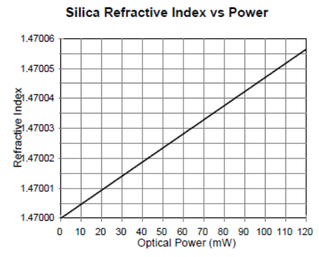 | Figure 1. Refractive Index of Silica vs Optical Power |
The second mechanism that generates non-linearities in fibre are scattering phenomena. These mechanisms give rise to Stimulated Brillioun Scattering (SBS) and Stimulated Raman Scattering (SRS). These nonlinearities are important because they represent the fundamental limiting mechanisms to the amount of data that can be transmitted on a single optical fibre [5].Stimulated Brillouin Scattering (SBS) nonlinearity imposes an upper limit on the amount of optical power that can be usefully launched into an optical fibre. The SBS effect has a threshold optical power, which when exceeded causes a significant fraction of the transmitted light to be redirected back toward the transmitter. This results in a saturation of optical power that reaches the receiver, as well as problems associated with optical signals being reflected back into the laser. The SBS process also introduces significant noise into the system, resulting in degraded BER performance [6]. Fig. 2 illustrates this phenomenon. The precise threshold for the onset of the SBS effect depends on a number of system parameters including wavelength (the threshold is lower at 1550nm than 1310nm) and line width of transmitter [8]. 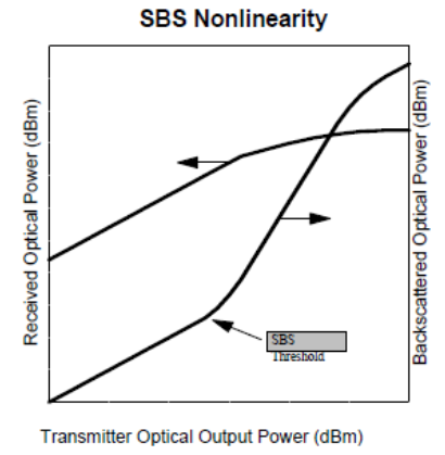 | Figure 2. SBS Threshold Effects |
In summary, nonlinear interactions between two signals in a fibre can be expressed by the change in the electric field of one of the signals caused by the other [9]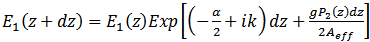 | (3) |
where α is the loss coefficient,  is the frequency dependent gain coefficient of the nonlinear process, and
  is the effective area of the fibre.When
  is real => gain or loss. Parametric interaction between photons and phonons, leading to– Stimulated Brillouin scattering (SBS)– Stimulated Raman scattering (SRS)When
  is imaginary => phase modulation.Modulation of refractive index by light intensity fluctuation, leading to– Self phase modulation (SPM)– Cross phase modulation (XPM)– Four-wave mixing (FWM)The nonlinear effect is a function of the transmission length. The longer the fibre link the more the light interaction and the greater the nonlinear effect. As the optical beam propagates along the link its power decreases because of fibre attenuation. The effective length
  is that length up to which power is assumed to be constant [4]. The optical power at a distance z along the link is given as
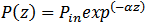 | (4) |
Where  is the input power (power at
  and α is coefficient of attenuation. For an actual link length(L), effective length is defined as
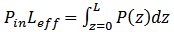 | (5) |
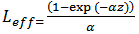 | (6) |
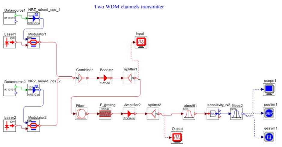 | Figure 3. Simulation setup for 2 WDMChannels transmitter |
Since communication fibre links are long enough so that . This results in
 . In optical fibre link with amplifiers the signal is amplified at each stage without correcting the effects of nonlinearities from previous stage. The effective length in such systems is the sum of the effective length of each stage. In a link of length L with amplifiers spaced l distance apart, the effective length is approximately
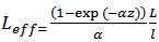 | (7) |
The effect of nonlinearities can be reduced by reducing the amplifier spacing.The effect of nonlinearity also increases with power in fibre, while power is inversely proportional to the area of the core. The effective cross-sectional area  is related to the actual area
  and the cross-sectional distribution of power intensity
  as follows [12]:
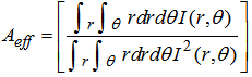 | (8) |
where and
and  denote the polar coordinates.
2. Simulation of Optical Fibre Nonlinear Effects in WDM Systems
In high-speed wavelength division multiplexed (WDM) systems, the interaction of fibre nonlinearity and dispersion leads to many degrading effects, limiting the total capacity as well as the achievable transmission distance.Major degrading effects due to fibre nonlinearity are Self Phase Modulation (SPM), Cross Phase Modulation (XPM), Four Wave Mixing (FWM), Stimulated Raman Scattering (SRS) and Stimulated Brillioun Scattering (SBS).Most nonlinear effects in optical fibres are observed by using short optical pulses because the dispersive effects are enhanced for such pulses. Propagation of optical pulses through fibres can be studied by solving Maxwell’s equations. In the slowly varying envelope approximation, these equations lead to the following nonlinear Schrodinger equation (NSE) [14]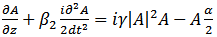 | (9) |
where A(z, t) is the slowly varying envelope associated with the optical pulse, α accounts for fibre losses,  governs the GVD effects, and γ is the nonlinear parameter defined as
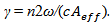 Here
Here  is the effective core area of the fibre. This equation is appropriate for pulses wider than 5 ps. For an accurate description of shorter pulses, several higher-order dispersive and nonlinear terms must be added to the NSE [13-14].
2.1. Self-Phase Modulation (SPM)
The nonlinear refraction index results in a phase change for the propagating light | (10) |
γ is the nonlinear coefficient. The phase change becomes significant when the power times the length of the system equals 1W-km | (11) |
SPM occurs when an intensity-modulated signal travels through a fibre. The signal is broadened in frequency domain by | (12) |
SPM can be used to compensate for positive chromatic dispersion (pulse narrowing).Except for SPM and XPM, all nonlinear effects provide gains to some channels at the expense of depleting power from other channels. SPM and XPM affect only the phase of signals and can cause spectral broadening, which leads to increased dispersion.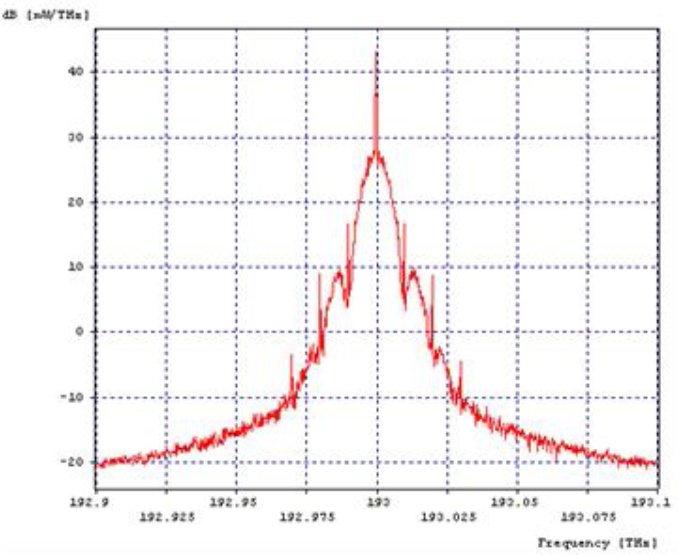 | Figure 4. SPM input pattern |
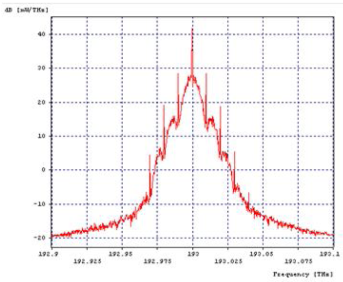 | Figure 5. SPM output pattern |
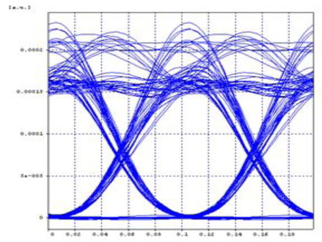
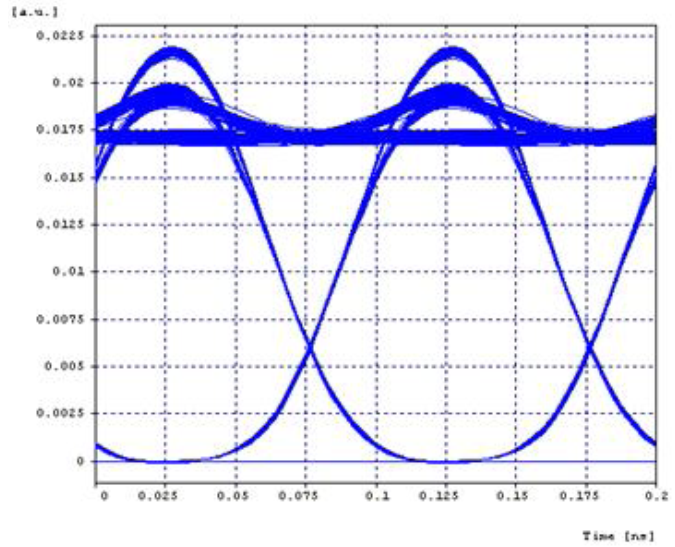 | Figure 6. SPM eye pattern |
 | Figure 7. XPM input pattern |
2.2. Cross-Phase Modulation (CPM/XPM)
CPM is very similar to SPM it arises from intensity fluctuations from other channels present in a WDM system. When two pulses travel down the fibre both will cause a change in refractive index as the optical power varies. If these two pulses happen to overlap, they will introduce distortion into each other.The frequency shift caused by CPM is given by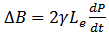 | (13) |
Since CPM is an interaction between channels, the presence of chromatic dispersion means that pulses from interfering channels will not remain superimposed on the pulses in the channel of interest.
2.3. Four-Wave Mixing (FWM)
FWM is a third-order nonlinearity caused by the nonlinear refractive index of the fibre. Example: If two signals with the frequencies  are traveling in the fibre, two new cross products will appear,
  and
and  . (Compare with IM3 and IP3 for electrical circuits). The number of interfering products increase rapidly with the number of signals (N) as
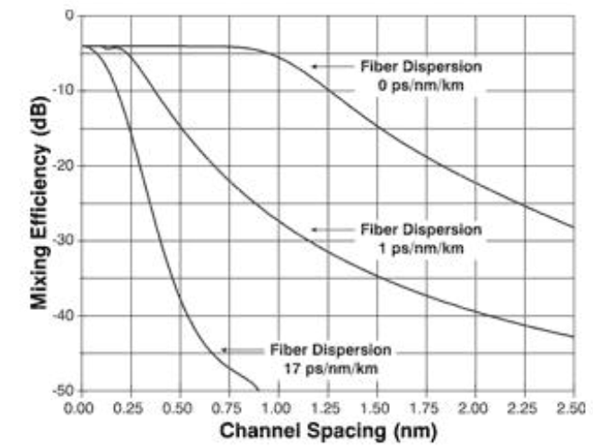
  For signals with equal channel-spacing the interfering signals will fall on top of the original ones. They cannot be removed by any means.Channel spacing strongly influences the magnitude of the FWM products, the further apart the better.Mixing efficiency is inversely proportional to the fibre dispersion, more dispersion means less FWM. This is illustrated in Fig.10 below.
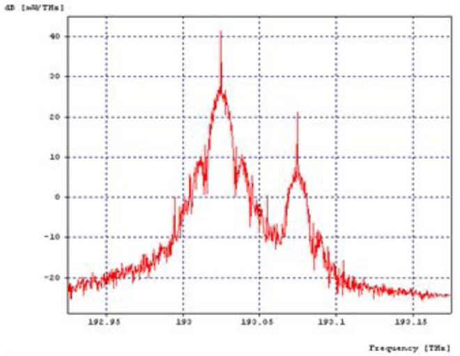
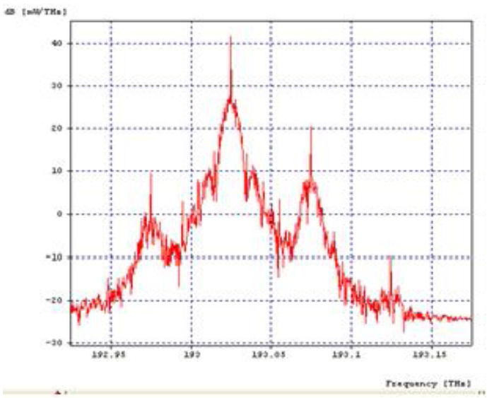 | Figure 8. XPM output pattern |
 | Figure 9. XPM eye pattern |
 | Figure 10. Mixing Efficiency (dB) vs Channel Spacing (cm) |
 | Figure 11. FWM input pattern |
3. Applications of the Fibre Nonlinearities
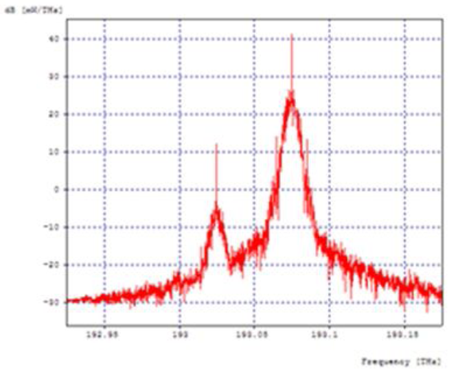
The nonlinear dispersion due to SPM is considered advantageous only when one WDM channel is used. In today’s world, challenge is to have more than one channel and higher transmission rate to receive the signal without distortion when transmitted through fibre link. Thus for multiplexed systems only XPM and FWM dispersion effects are considered. From the table and the related eye patterns, it is observed that XPM effect causes serious distortion in the signal. Whereas in FWM effect, high improvement of Q factor is seen at the expense of eye opening, this is due to generation of new signal at a cost of power.On the other hand, optical nonlinearities can be very useful for a number of applications, starting with distributed in-fibre amplification and extending to many other functions, such as wavelength conversion, multiplexing and demultiplexing, pulse regeneration, optical monitoring, and switching. The widely-used radio communications modulation scheme Orthogonal Frequency Division Multiplexing (OFDM) [1] can also be used to compensate for fibre chromatic dispersion in ultra-long haul communications links [7].In this section some of the applications of nonlinearities of optical fibres are described with simulated results.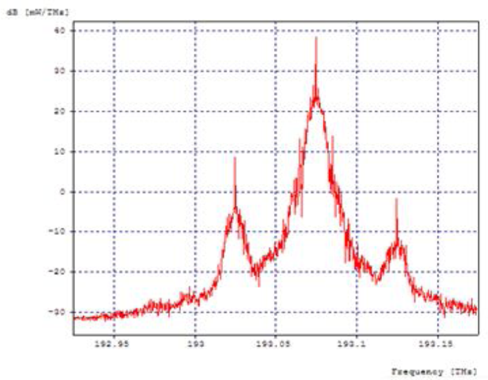 | Figure 12. FWM output pattern |
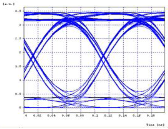 | Figure 13. FWM eye pattern |
3.1. Wavelength Conversion
When pump light and probe light are input into an optical fibre, converted light (idler light) is generated at a wavelength shifted away from the pump light wavelength toward the shorter wavelength by  (frequency difference between signal and pump lights). The power of converted light becomes small when
  becomes large. The
  value at which the power of converted light becomes half of the maximum value is measured on both sides of the pump light wavelength, and the total of the two
  values (twice of
  in general) is called conversion bandwidth.
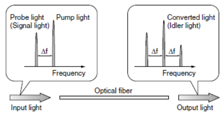 | Figure 14. Concept illustration of FMW-based wavelength Conversion |
The FWM wavelength conversion efficiency in a 100 m length of this nonlinear fibre was measured on the experimental setup shown in Fig. 15. The  fluctuation along the length direction of the evaluated fibre is suppressed to ±0.1 nm or less.
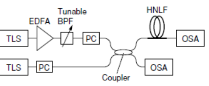 | Figure 15. FMW wavelength conversion measurement setup. (TLS: Tunable Light Source, PC: Polarisation Controller, OSA: Optical Spectrum Analyser |
Fig. 16 shows the measured probe light wavelength dependency of the converted light power. The measurement values were normalized to the maximum value of the converted light power. The theoretical calculation result is also shown in the figure as the solid line. From the measurement result, it was confirmed that the conversion bandwidth is more than 193 nm. Although the measurement cannot be done for the probe light wavelength of 1650 nm or higher on the currently used experimental setup, the conversion bandwidth of 220 nm is predicted from the calculation result, as shown in Fig. 16.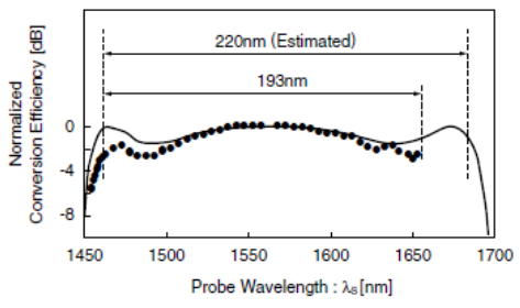 | Figrue 16. FWM wavelength conversion efficiency vs probe light wavelength (filled circles: experimental results, solid line: calculated result |
3.2. Raman Amplification
In the Raman amplification, the pump efficiency decreases when the transmission loss at the pump wavelength is increased. Especially in the case of Highly Non-Linear Fibre (HNLF), because germanium concentration doped to the center core area is about ten times higher than that of a standard single mode fibre, Rayleigh scattering becomes remarkable and the fibre loss increases inherently. Moreover, in the case of standard optical fibre that has the water absorption peak at around 1380 nm, when the pump wavelength is set in the vicinity of this wavelength, the pump efficiency significantly decreases. Fig. 17 shows the Raman gain coefficients of different types of optical fibres. Although a dispersion compensating fibre (DCF) is usually applied, HNLF shows the highest Raman gain coefficient and is more suitable for a discrete Raman amplifier.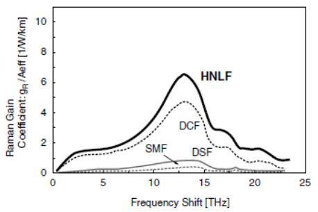 | Figure 17. Raman gain coefficients of various optical fibres (SMF: single mode optical fibre, DCF: dispersion compensating fibre) |
Although Raman amplification has an advantage that the amplification gain is not dependent on the dispersion characteristics, in the case of WDM amplification, interactions caused by optical nonlinearity among the amplified signals need to be avoided. Figure 18 shows the measurement result of the relationship between the dispersion values and the transmission penalty of different HNLFs when 8 x 10Gb/s WDM signals were amplified. 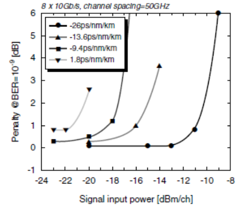 | Figure 18. Relationship between WDM signal input power and transmission penalty in HNLF Raman amplifier (HNLF length 5km, Raman gain about 20dB) |
The transmission penalty is the difference of the sensitivity of the receiver at BER = 10-9 between the cases with and without the discrete Raman amplifier using a HNLF. It was observed that the maximum allowable input power becomes smaller when the absolute value of dispersion becomes larger. From this observation, it became evident that the dispersion value of a HNLF used in a Raman amplifier must be optimally designed.
4. Conclusions
Stimulated Raman scattering is attracting a lot of attention for making broadband optical amplifiers. Similarly, FWM has been used for channel demultiplexing in a WDM lightwave system. FWM is also harmful for WDM systems since it leads to interchannel crosstalk, and the dispersion management technique is often used to suppress it. The presence of these non linear effects in the optical fibre communication system like WDM systems can adversely affect the communication between two receiving ends. These nonlinear effects can be managed through proper system design. The effects are also useful for many device and system applications like optical switching, soliton formation, wavelength conversion, broadband amplification, de-multiplexing etc. In this work the comparison of nonlinearities was performed using eye pattern with respect to bit error rate & Q factor. From the results shown in Figs. 6, 9, and 13, it is observed that in FWM effect, high improvement of Q factor is seen at the expense of eye opening, which is due to generation of new signal at a cost of power. It is concluded that FWM nonlinear effect is more advantageous and effective as compared to SPM and XPM.
References
| [1] | G.P. Agrawal. Nonlinear fibre optics. Academic Press, 2001. |
| [2] | J. Toulouse: Optical Nonlinearities in Fibres: Review, Recent Examples, and Systems Applications. Journal of Lightwave technology, vol. 23, No. 11 November 2005. |
| [3] | S.P. Singh and N. Singh: Nonlinear Effects in Optical Fibres: Origin, Management and Applications. Progress in Electromagnetics Research, PIER 73, 249-275, 2007. |
| [4] | R. Ramaswami and K. Sivarajan, Optical Networks – A Practical Perspective, Morgan Kaufmann Pub. Inc; San Francisco, 1998. |
| [5] | David R. Goff, The effects of Fibre Nonlinearities, Oslo Technology Inc; 6 Feb 2007. |
| [6] | B.K. Mishra, Lochan Jolly, Karishma Mhatre International Journal of Scientific & Engineering Research Volume 4, Issue3, March-2013 1 ISSN 2229-5518. |
| [7] | A. J. Lowery and J. Armstrong, “Orthogonal- frequency-division multiplexing for dispersion compensation of long-haul optical systems,” Opt. Express 14, 2079-2084 (2006). |
| [8] | Stefan Andersson “Fibre Nonlinearities and Their Impact on Transmission Systems” March 28, 2005 Electronics Devices. |
| [9] | A. Boh Ruffin, M. J. Li, X. Chen, A. Kobyakov, and F. Annunziata, Brillouin gain analysis for fibres with different refractive indices, Opt. Lett. 30 (23), pp. 3123–3125, 2005. |
| [10] | A. Kobyakov, S. Kumar, D.Q. Chowdhury, A. B. Ruffin, M. Sauer, S. R. Bickham and R. Mishra, Design concept for optical fibres with enhanced SBS threshold, Opt. Exp.13 (14), pp. 5338–5346, 2005. |
| [11] | Y. Koyamada, S. Sato, S. Nakamura, H. Sotobayashi, and W. Chujo, Simulating and designing Brillouin gain spectrum in single mode fibres, J. Lightwave Technol. 22 (2), pp. 631–639, 2004. |
| [12] | C. K. Jen, J. E. B. Oliveira, N. Goto, and K. Abe, Role of guided acoustic wave properties in single-mode optical fibre design, Electron. Lett. 24 (23), pp. 1419–1420, 1988. |
| [13] | Toshiaki OKUNO, Masaaki HIRANO, Tetsuya NAKANISHI and Masashi ONISHI: “Highly-nonlinear Optical Fibres and Their Applications” SEI TECHNICAL REVIEW · NUMBER 62 · JUNE 2006. |
| [14] | Govind P. Agrawal: “Non-Linear Fibre Optics”, LNP 542, pp. 195−211, 2000. Springer-Verlag Berlin Heidelberg 2000. |
 Abstract
 Reference
 Full-Text PDF
 Full-text HTML