Ching-Hung Chang1, Ami Amrullah2
1Department of Electrical Engineering, National Chiayi University, Chiayi City, 60004, Taiwan, R.O.C
2Department of Computer Science and Information Engineering, National Chiayi University, Chiayi City, 60004, Taiwan, R.O.C
Correspondence to: Ching-Hung Chang, Department of Electrical Engineering, National Chiayi University, Chiayi City, 60004, Taiwan, R.O.C.
| Email: |  |
Copyright © 2012 Scientific & Academic Publishing. All Rights Reserved.
Abstract
A steady-gain C-band Erbium-doped fiber amplifier (EDFA) is proposed to assist the transmission performance in multi-wavelength long-distance fiber optical transport networks. Different from the published gain-clamped EDFAs which utilize an in-line device to steady their performance in L-band, this proposal is focusing on the C-band and is employing an off-line feedback lightwave technique to clamp the gain variation. The effect of the off-line technique is theoretically studied and the outcomes are employed to optimize the proposed technique. simulation results show that when a saturated optical carrier and 14 individual tested optical carriers located from 1530 nm to 1565 nm are inserted in to the proposed EDFA, the maximum gain variation for the 14 normal optical carriers are efficiently reduced from 2 dB to 0.11 dB. Almost 20 times improvement in the gain stability is achieved to practically eliminate the accumulated power variation caused by the cascaded in-line EDFAs in a long distance fiber optical link. This achievement will greatly ensure the overall transmission performance and will significantly assist a system provider to estimate the power budget in each link.
Keywords:
Erbium-doped Fiber Amplifier, Gain-clamping, Fiber Optical Transport System, Multi-wavelength
Cite this paper: Ching-Hung Chang, Ami Amrullah, A Steady-Gain C-band EDFA for Multi-Wavelength Fiber Optical Transport Networks, International Journal of Optoelectronic Engineering, Vol. 3 No. 1, 2013, pp. 6-11. doi: 10.5923/j.ijoe.20130301.02.
1. Introduction
Following with the evolution of triple-play multimedia services, the explosive growth of the Internet and data traffics have placed huge bandwidth demands on current communication network systems. To deal with this tendency, all optical fiber optical transport systems are developed continuously to increase the overall network capacity, and fiber optical amplifiers are investigated widely to extend the network reach limit imposed by fiber attenuation and losses in optical networks[1]. In this aspect, Erbium-doped fiber amplifier (EDFA) with high-gain, large output power and low noise figure (NF) characteristics has been designed widely to support data transmissions in fiber optical transport systems[2-5]. However, when the gain and NF performances in those EDFAs are promoted, their stability becomes another issue to limit the transmission performance. An in-line optical lightwave may obtain different gain values when other lightwaves are also fed into those EDFAs. These variations will make a difficulty to estimate power budget for each optical line in a multi-wavelength fiber optical transport system and will seriously reduce the overall transmission performance. This phenomenon in a long-distance transport system is more critical because it needs to utilize 5, 10 or even more EDFAs in its link. For example, if there are 10 EDFAs in a fiber optical link and each one cause a 2 dB gain variation for a random wavelength, the accumulated power variation for that wavelength will up to 20 dB. Such power fluctuate will cause serious power budget issues and will significantly impact the transmission performance. Therefore, developing a stable EDFA has become an important technique and research topic in recent years[6-8].In the literature, gain-clamping method is widely employed to deal with the EDFA stability, and is generally achieved by adding an extra lightwave into the gain medium, which can share upper energy ions together with the signal lights. For example, in[9-11], the gain-clamped EDFAs are composed by utilizing a broadband fiber Bragg grating (FBG) to recycle a portion of EDFA amplified spontaneous emission (ASE) noise back into the input port. The reflective lightwave will clamp the EDFA with a steady gain performance. Nevertheless, those researches are focusing on utilizing a fixed bandwidth FBG to achieve gain-clamped L-band EDFA. The effect of the feedback-lightwavelinewidth values in the C-band EDFA have not been theoretically analyzed yet. Besides, the FBG in those L-band EDFA is applied in-line. When the temperature or pressure is changed, its reflect window will be changed, so the gain-clamping performance may not be ensured and the in-line optical signals may also be reflect by the FBG. To overcome these drawback, we propose a gain-clamped C-band EDFA basing on an off-line optical band-pass filter (OBPF). With a theoretically analysis on the relationship among the feedback-lightwavelinewidth, the EDFA gain, NF and the amplification stability, an optimized C-band EDFA is obtained to provide up to 20 times gain stability improvement for multi-wavelength fiber optical transport systems..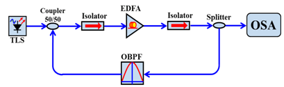 | Figure 1. Simulation setup of the proposed gain-clamped C-band EDFA |
2. Simulation Setup
To evaluate the proposed gain-clamped C-band EDFA, a simulation, as shown in Figure 1, was setup utilizing OptiSystem. In this setting, a C-band EDFA was composed by a span of 10-m EDF and a 980 nm 250 mW pumping lightwave, and two optical isolators were added in each side of the EDFA to block any reflected lightwave. The gain-clamping feature was achieved by utilizing an optical splitter, a tunable OBPF and an optical combiner to loop-back part of the EDFA output ASE noise. To evaluate the proposal, a signal lightwave generated from a tunable laser (TL) was fed into the gain-clamped EDFA and its amplification was observed by an optical spectrum analyzer (OSA). In order to investigate the relationship among the loop-back lightwavelinewidth, the EDFA gain, NF and amplification stability, the OBPF pass-band was set to 1532.73 nm which is located at the highest power level of the ASE noise, and the pass-band bandwidth (OBPF-BW) was adjusted from 1 GHz to 10 GHz. The optimized OBPF-BW value was then employed to compose the proposed C-band EDFA.
3. Results and Discussion
To evaluate the EDFA small signal gain performance under various OBPF-BW values, the tested signal lightwave was set to 1550 nm and its power level was adjusted from -50 dBm to -10 dBm. The relative results are collected and shown in Figure 2. In general, an EDFA gain performance versus input lightwave power level can be described by[12]: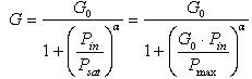 | (1) |
where the G0 and G are the small-signal gain and the saturated gain for a given input lightwave power Pin, respectively. In this setting, the G0 is roughly equal to 40 dB, and the α and Psat are two unknown parameterswhichcharacterize the gain saturation. The Pmax = G0‧Psat represents the maximum output power of the amplifier. In here, the input lightwave will be multiplexed with the recycled lightwave before been fed into the gain-clamed EDFA. According to the equation, when the OBPF-BW is increased from 1 GHz to 10 GHz, the overall Pin will be boosted up causing a smaller gain value. As illustrated in the Figure 2, when the signal lightwave power is under Psat (around -25 dBm) the maximum gain deviation among 1 GHz OBPF-BW to 10 GHz OBPF-BW scenarios is roughly 3.74 dB. This means that choosing a smaller OBPF-BW value can provide a larger gain value for the proposed gain-clamped EDFA.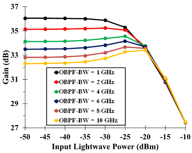 | Figure 2. EDFA gain characteristic versus various input lightwave powers at different OBPF-BW values |
| Table 1. The Gain Variations When the Input LightwavePower Is Increased from -50 dBmto -25 dBm |
| | OBPF-BW | Gain variation | | 1 GHz | 0.76 dB | | 2 GHz | 0.15 dB | | 4 GHz | 0.43 dB | | 6 GHz | 0.66 dB | | 8 GHz | 0.85 dB | | 10 GHz | 0.97 dB |
|
|
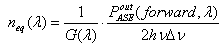
Furthermore, to observe the gain stability, the maximum gain variation among different input signal powers (-50 dBm to -25 dBm), are recorded in Table 1. It is clear that the minimum gain variation value (0.15 dB) is presented at the 2 GHz OBPF-BW scenario and the worst case (0.97 dB) is presented at the 10 GHz one. The 0.82 dB (0.97dB-0.15dB) different between these two scenarios proves that the EDFA gain stability can be enhanced by a suitable feedback-lightwavelinewidth. Similar with the EDFA gain analysis, the relative EDFA NF performances are also observed and illustrated in Figure 3 as well as the maximum NF variations among different input signal powers (-50 dBm to -20 dBm) are recorded and illustrated in Table 2. The EDFA NF spectrum (NF(λ)) can be determined from its gain (G(λ)) at the wavelength of λ and spontaneous emission factor spectra (nsp(λ)) or equivalent input noise factor (neq(λ)), and can be given by[13]: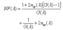 | (2) |
wherethensp(λ)andneq(λ) are defined by: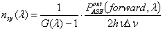 | (3) |
 | (4) |
where  is the power of the forward ASE noise at the wavelength of λ, Δλ is the linewidth of signal, h is Planck constant, and c is speed of light in vacuum. These equations indicate that the EDFA NF is in proportion to the power of the forward ASE and the gain. As a result, the best NF value (6.47 dB) is presented at the 10GHz OBPF-BW scenario and the worse one (7.35 dB) is presented at the 1GHz OBPF-BW scenario. Nevertheless, to discuss the NF stability, the lowest NF variation (0.09 dB) shown in the Table 2 is presented at the 1 GHz OBPF-BW scenario and the second one (0.19 dB) is located at 2GHz OBPF-BW one.
| Table 2. The NF variations when the input lightwave power is increased from -50 dBm to -20 dBm |
| | OBPF-BW | NF variations | | 1 GHz | 0.09 dB | | 2 GHz | 0.19 dB | | 4 GHz | 0.30 dB | | 6 GHz | 0.33 dB | | 8 GHz | 0.34 dB | | 10 GHz | 0.33 dB |
|
|
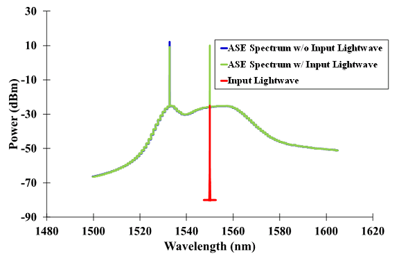
As the discussion in the Introduction section, the EDFA stability is an important issue in a long distance fiber optical transport system. To summary the gain and NF performances in the discussed OBPF-BW scenarios, the 2GHz OBPF-BW scenario with its outstanding performance in the gain and NF stability makes it as the most suitable one to optimize the proposed gain-clamped C-band EDFA and will be utilized in the following simulations.Following with the previous discussions, the efficiency of the proposed off-line feedback-lightwave technique is evaluated by inserting a test lightwave into the EDFA, and the relative output spectra without and with the proposed gain-clamping circuit are shown in Figure 4 and Figure 5, respectively. Without the proposed circuit, the EDFA output ASE power presented at the Figure 4 will decline roughly 2-3 dB when a -25 dBm 1550 nm lightwave is fed into it. Nevertheless, when an extra ASE lightwave is loop-backed to share the upper energy ions in the EDFA, the EDFA output ASE power levels are almost the same in both cases. Furthermore, to evaluate the proposal in different input wavelength, the test lightwave is also changed from 1550 nm to 1560 nm, 1540 nm and 1530 nm, and the obtained EDFA output spectra are superimposed and shown in Figure 6. No obvious ASE difference is presented among these four ASE spectra. These similar ASE spectra demonstrate the efficiency of the proposal to provide a steady gain value for any specific wavelength.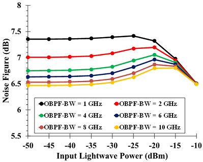 | Figure 3. EDFA noise figure characteristic versus various input lightwave powers at different OBPF-BW values |
Finally, to investigate the EDFA gain performance while a saturation input lightwave is also fed into the EDFA, one more TL was employed to generate a 1550 nm, -23 dBm saturation input lightwave, and the original TL was still employed to gradually produce a fixed -35 dBm input power but different wavelengths. The obtained gain values with and without the saturation lightwave and the loop-back circuit are shown in Figure 7. In the open-ring scenario (without OBPF), the obtained gain values for different wavelengths are reduced when the saturation input lightwave is added. A roughly 2 dB gain reduction is presented at the 1530-1540 nm range and roughly 1 dB gain reduction is observed at the 1540-1560 nm range. Fortunately, these gain variations are not presented in the close-ring scenario (with OBPF). With the proposed gain clamping technique, the maximum gain variation in the entire C-band is controlled within 0.11 dB. Such 10 ~ 20 times improvement will efficiently assist a system manager to accurately estimate the power budgets in multi-wavelength fiber optical transport systems and will promote the end-to-end data transmissions. | Figure 4. EDFA output ASE Spectra with and without an input lightwave |
 | Figure 5. EDFA noise figure characteristic versus various input lightwave powers at different OBPF-BW values |
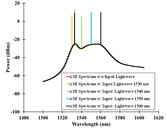 | Figure 6. The overlapped EDFA output ASE Spectra in various input wavelength scenarios |
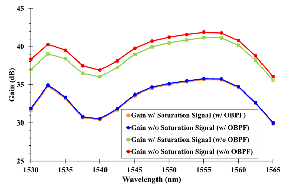 | Figure 7. The obtained EDFA gain performance with and without an input saturation lightwave and the proposed feedback circuit |
4. Conclusions
A wide-range and steady-gain C-band EDFA is proposed for multi-wavelength fiber optical transport systems. Different from the published EDFA structures which the provided gain performance for any one wavelength is changed with the variation of the inserted lightwave number, the proposed EDFA architecture provide a much steady gain performance for each input wavelength. Such steady-gain performance is especially important for long distance fiber-optical transport systems because the cascaded gain-variations from the in-line EDFAs will significantly limit the transmission performance. For example, if there are 5 EDFA in a transport link and each of them induced a 2 dB power variation, the overall 10 dB power variation will significantly impact the system performance. To overcome this phenomenon, numbers of methods are developed to clamp the gain variation by adding in-line devices in a L-band EDFA. However, such in-line devices may also influence the passedlightwaves and their gain-clamping function may be reduced or eliminated by the deployed environment, so this proposal is focusing on the C-band EDFA and is utilizing an off-line feedback lightwave technique to clam the gain variation. Following with a theoretically analysis on the proposed feedback technique, a high-steady C-band EDFA is achieved by the optimized feedback-lightwave parameters. Simulation results proof that the gain variation in the entire C-band is efficiently reduced from 1~2 dB to around 0.11 dB. Such 10 ~ 20 times improvement demonstrates the advancement of the proposal to be employed in multi-wavelength fiber optical transport systems.
ACKNOWLEDGEMENTS
The authors would like to thank the financial support from the National Science Council of the Republic of China under Grant NSC 101-2221-E-415-009-MY2.
References
| [1] | R. Malik, "Experimental Study of All-optical Gain-clamped Fiber Optical Parametric Amplifier", IEEE, Photonic Technology Letters, vol. 24, no. 8, pp. 664-666, 2012. |
| [2] | B. Bouzid, "High-gain and Low-noise-figure Erbium-doped Fiber Amplifier Employing Dual Stage Quadruple Pass Technique", SpringerLink, Optical Review, vol. 17, no. 3, pp. 100-102, 2010. |
| [3] | S. Aleksic, “Energy and Entropy Flow in Erbium-doped Fiber Amplifiers: a Thermodynamic Approach”, IEEE/OSA, Journal of Lightwave Technology, vol. 30, no. 17, pp. 2832-2838, 2012. |
| [4] | I. Nusinsky, A. A. Hardy, “Multichannel Amplification in Strongly Pumped EDFAs”,IEEE/OSA, Journal of Lightwave Technology, vol. 22, vo. 8, pp. 1946-1952, 2004. |
| [5] | M. Murakami, T. Seki, K. Oda, “Optical Signal Channel Power Stability in a Transparent Optical Network Using Large-scale Photonic Cross Connects and Automatic Gain Control EDFAs”, IEEE/OSA, Journal of Optical Communications and Networking, vol. 2, no. 1, pp. 20-27, 2010. |
| [6] | M. Zannin, S. Mangeni, S. Taccheo, K. Ennser, P. Barlet, D. Careglio, “Investigation of All-optical Gain Clamped Erbium-doped Amplifier in the Presence of Variable Burst Traffic”, inProceedings of 2011 SPIE Optical Components and Materials VIII, pp. 7934, 2011. |
| [7] | S. X. Cheng, B. A. Hamida, A. W. Naji, H. Arof, H. Ahmad, S. W. Harun, “Compact and Wide-band Bismuth-based Erbium-doped FibreAmplifier Based on Two-stage and Double-pass Approaches”, IET, Optoelectronics, vol. 6, no. 3, pp. 127-130, 2012. |
| [8] | M. Pal, S. Bandyopadhyay, P. Biswas, R. Debroy, M. C. Paul, R. Sen, K. Dasgupta, S. K. Bhadra, “Study of Gain Flatness for Multi-channel Amplification in Single Stage EDFA for WDM Applications”, SpringerLink, Optical and Quantum Electronics, vol. 39, no. 14, pp. 1231-1243, 2008. |
| [9] | J. Lin, W. Ho, “Dynamic-performance Characterization of C-band EDFA Using ASE-power Peak-selective Feedback Gain-clamping”, IOP, International Journal of Laser Physics, vol. 22, no.4 , pp. 765-769, 2012. |
| [10] | S. W. Harun, N. M. Samsuri, H. Ahmad, “Tunable and Low Noise Gain-clamped Double-pass L-band Erbium-doped Fiber Amplifier”, JSAP, Japanese Journal of Applied Physics, vol. 43, no.8B , pp. L1075-L1077, 2004. |
| [11] | S. Hsu, T.-C. Liang, “Optimal Design of Optically Gain-clamped L-band Erbium-doped Fiber Amplifier by Fiber Bragg Grating Method”, JSAP, Japanese Journal of Applied Physics, vol. 43, no. 8A, pp. 5325-5329, 2004. |
| [12] | X. Zhang, A. Mitchell, “A Simple Black Box Model for Erbium-doped Fiber Amplifiers”, IEEE, Photonic Technology Letters, vol. 12, no. 1, pp. 28-30, 2000. |
| [13] | E. Desurvire, Erbium-doped fiber amplifiers: principles and applications, Wiley,New York, 1994. |
 Abstract
 Reference
 Full-Text PDF
 Full-text HTML