-
Paper Information
- Paper Submission
-
Journal Information
- About This Journal
- Editorial Board
- Current Issue
- Archive
- Author Guidelines
- Contact Us
International Journal of Networks and Communications
p-ISSN: 2168-4936 e-ISSN: 2168-4944
2022; 12(1): 1-27
doi:10.5923/j.ijnc.20221201.01
Received: Jan. 14, 2022; Accepted: Jan. 29, 2022; Published: Feb. 15, 2022

Toward 600 Gbps and 1 Tbps per Wavelength Data Transmission for Coherent WDM-PON Supporting 5G and Beyond Services
 Abstract
 Reference
 Full-Text PDF
 Full-text HTML
Ahmed H. Abdulhussein, Raad S. Fyath
Department of Computer Engineering, Al-Nahrain University, Baghdad, Iraq
Correspondence to: Raad S. Fyath, Department of Computer Engineering, Al-Nahrain University, Baghdad, Iraq.
| Email: |  |
Copyright © 2022 The Author(s). Published by Scientific & Academic Publishing.
This work is licensed under the Creative Commons Attribution International License (CC BY).
http://creativecommons.org/licenses/by/4.0/

Next generation mobile networks are expected to operate with more than 100 Gbps (toward 1 Tbps) per single wavelength data rate and high-order modulation (HOM) format to support the required ultra-high data services. Wavelength-division multiplexing (WDM) access techniques could be used to provide huge data capacity, extended coverage, long reach connection, and high flexibility. In this paper, design issues for coherent WDM passive optical networks (PONs) to support fifth-generation (5G) and beyond 5G services are presented. The target is to achieve 600 Gbps and 1 Tbps data rates per single wavelength through using HOMs, dual polarization (DP) 64- and 128-QAM, to support eight and sixteen small cells per macro cell; each small cell is served by a single wavelength. The designed configurations are implemented using Optisystem software ver. 15.0. For a 16-small cell configuration operating with 64-QAM modulation format, the achieved maximum reach  is 60 and 20 km for data rate per wavelength
  = 600 Gbps and 1 Tbps, respectively. Further,
  = 45 and 15 km for the same cell configuration operating with 128-QAM signaling and
  = 600 Gbps and 1 Tbps, respectively.
Keywords: High-order modulation (HOM), Wavelength-division multiplexing (WDM), Passive optical network (PON), WDM-PON, 5G network
Cite this paper: Ahmed H. Abdulhussein, Raad S. Fyath, Toward 600 Gbps and 1 Tbps per Wavelength Data Transmission for Coherent WDM-PON Supporting 5G and Beyond Services, International Journal of Networks and Communications, Vol. 12 No. 1, 2022, pp. 1-27. doi: 10.5923/j.ijnc.20221201.01.
Article Outline
1. Introduction
- The specification of fifth-generation (5G) mobile networks has already passed the standardization phase, and these networks are being rolled out around the world since 2020. The 5G technology was driven by the commercial operators to accommodate future data capacity requirements for this customer base, as well as complemented by efficient manufacturing demands from industry in the shape of internet of things (IoT) [1]. On the other hand, the demand for the high-speed passive optical networks (PONs) has been increasing due to the spread of broad services [2-6]. Recently, the IEEE 802.3ca Task Force has commenced discussion of the first 100 Gbps-based PON standard in the form of 100G Ethernet PON (100G-EPON) [7]. This PON can support the first stage of the growing bandwidth demands for forthcoming 5G networks. Figure 1 illustrates the bandwidth demands for forthcoming 5G mobile front-haul (MFH) and mobile back-haul (MBH) networks based on PON. The future MFH/MBH can operates with a data rate of 100 Gbps per small cell and up to around 1 Tbps per macro cell incorporating multiple small cells. Further, the transmission rate per small cell is itself expected to increase exponentially to a maximum MFH link rate of 1 Tbps, depending on future wireless user rates such as beyond 5G (B5G) and sixth-generation (6G) mobile systems [8]. The wavelength-division-multiplexing (WDM) access techniques could provide huge data capacity, extended coverage, long reach connection, and high flexibility [9]. Thus, it is expected that the performance of PON is enhanced strongly when its operation is based on the WDM technique, especially for mobile network applications [10-15]. In this case, the WDM-PON serves each small cell with a single wavelength for downstream (upstream) signal. The WDM-PON performance will be enhanced further when coherent optical detection is used to recover the data at the user end, which this leads to what is known as coherent WDM-PON. The coherent technology is considered a promising candidate for realizing such higher-bandwidth PONs due to its high receiver sensitivity, superior to intensity modulation/direct detection-based PON [10]. Further the coherent PON easily leaves space for inserting additional wavelength to accommodate additional users (optical node units) with the same optical distribution network. Another advantage of coherent PON is that it is the only technique available right now for carrying a signal at 100 Gbps or more per single wavelength.
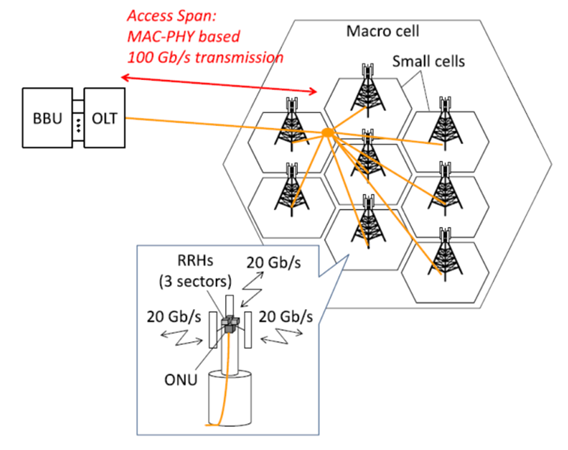 | Figure 1. Bandwidth demand for 5G MFH/MBF-based PON technology [8] |
 from 100 Gbps to 1 Tbps for each WDM channel [8]. This issue is addressed in the paper for two values of
  , 600 Gbps and 1 Tbps. To increase
  toward 1 Tbps, one can use a hybrid of techniques, including high-order modulation (HOM), high symbol rate, and dual-polarization (DP) multiplexing. Increasing modulation order means increasing the number of bits carried by each symbol while decreasing the distance between symbols in the constellation diagram. This leads to decrease in the transmission distance. Although, increasing the symbol rate
  will increase
  for the same value of modulation order. Most of the coherent optical communication systems and optical networks demonstrated in the literature use
  not exceeding 100 GSps due to the speed limit of electronic-to-optical (and vice versa) conversion. Increasing the symbol rate requires increasing the speed of the digital-to-analog (DAC) (and vice versa ADC) conversion. Note that increasing either the symbol rate or modulation order has advantages and disadvantages. Depending on the system requirements, some combination of them is likely to be used. This issue is addressed on this paper as related to next generation mobile networks.It is worth to mentioning here that different research groups have started an investigation to design coherent WDM optical communication system carrying data rates of 1 Tbps per wavelength. Most of their results appeared as a short announcement on multimedia websites [16]. Recently, Buchali et al. [17] have reported the implementation of 128 GSps DAC to enable 1.52 Tbps single-carrier transmission over 80 km of single-mode fiber. Nokia has given a talk in OFC 2021 summarizing their progress in beyond 1 Tbps transmission [18]. Even these works are related to point-to-point optical communication systems, the concepts may be adapted or modified to support the goals to be achieved by future coherent WDM-PON for next generation mobile networks.
2. Related Works
- In 2017, Suzuki et al. [10] presented the 100 Gbps per λ-based coherent WDM-PON prototype system. A real-time 100 Gbps coherent transceiver with a simplified digital signal processing (DSP) suitable for access spans was highlighted. In 2018, Suzuki et al. [8] presented design concepts for a coherent WDM-PON operating with a 100 Gbps data rate per channel. Issues related to miniaturization optimization of DSP-based embedded coherent transceivers were given.In 2018, Matsuda et al. [19] demonstrated hardware-efficient carrier phase recovery and adaptive equalization for 100 Gbps per λ based coherent WDM-PON systems. Downstream transmission with 32 Gbaud (GSps) DP-quadrature phase shift keying (QPSK) signals and offline DSP was demonstrated. In 2019, Shbair and Nahal [20] reviewed the latest progress of coherent WDM-PON technology operating with 100 Gbps per λ and investigated the system performance when QPSK and DP-QPSK modulation formats are used.In 2019, Luo et al. [21] proposed a scheme of coherent ultra-dense WDM-PON for symmetrical operations between the uplink and downlink. They experimentally used a real-time field-programmable gate array-based transceivers were used to demonstrate a field trial operation.In 2020, Segarra et al. [22] reported a low-cost coherent ultra-dense WDM-PON with 6.25 GHz channel spacing. The optical network unit was made by implementing coherent transceivers that have two paired low-cost distributed feedback lasers.In 2020, Luo et al. [23] proposed a 100 Gbps coherent ultra-dense WDM-PON structure with EDFA that was placed with high power budget at the OLT side for optical signals amplification for both the uplink and downlink. A real-time 4 × 25 Gbps network at 12.5 GHz channel spacing over 50 km SSMF was experimentally demonstrated.In 2021, Zhou et al. [24] experimentally demonstrated DSP-free 8 × 10 Gbps 4-level pulse-amplitude modulation transmission for coherent WDM-PON cost-effective with channel spacing of 20 GHz in the C-band. The polarization-independent coherent receiver was used at the ONU.It is clear from this survey that most of the work was related to about 100 Gbps per λ data rate and to modulation order 16 or less. Next generation networks are expected to operate with more than 100 Gbps per λ data rate (toward 1 Tbps per λ) and high-order modulation format (64- and 128-QAM) to support the required ultra-high data services. These issues will be addressed in this paper.
3. Design Issues and Configurations for Coherent WDM-PONs Supporting 5G and Beyond Services
- This section presents the design issue for coherent WDM-PONs to support 5G and beyond 5G (B5G) services. The target is to achieve 600 Gbps and 1 Tbps data rates per single wavelength through using high-order modulations, dual-polarization (DP) 64- and 128-QAM. The designed configurations are implemented using Optisystem software ver. 15.0.Figure 2 illustrates the schematic of WDM-PON for distributing mobile services. The mobile front-haul (MFH) networks consist of: (i) an optical line terminal (OLT) incorporating an optical multiplexer to collect the data from the baseband network unit (BBU) located in the base station after optical modulations; (ii) optical network unit (ONU) incorporating optical demultiplexer to serve multi optical receiver/antenna units; and (iii) standard single-mode fiber (SSMF) acting as the transmission link between the OLT and the ONU.
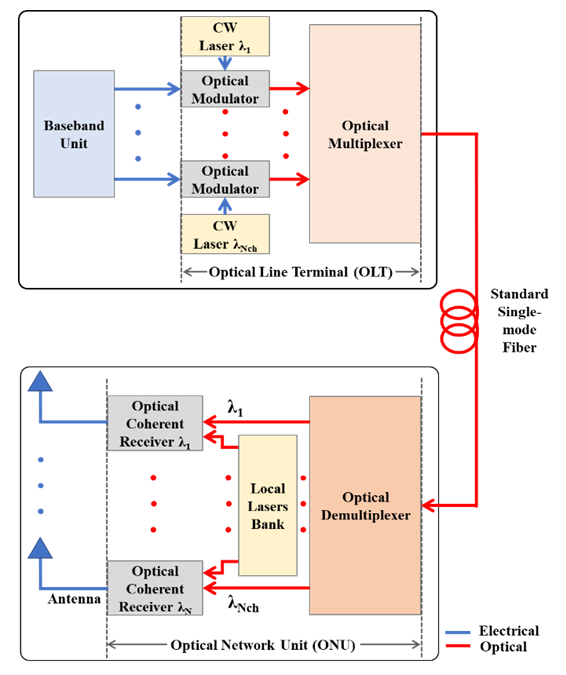 | Figure 2. Simplified schematic of the WDM-PON for mobile service |
 of 25, 50, …, 200 GHz.(iii) No active element is inserted in the transmission fiber link, such as optical amplifiers and optical-to-electrical (and vice versa).(iv) The ONU supports the service to a macro cell incorporating multiple small cells with each cell is related to one of the used WDM channels wavelengths. Each cell has its own remote radio head (RRH), i.e., antenna, covering 3 or 6 sectors. Since the standard WDM system uses
  channels, where n is a positive integer,
  and
and  are adopted in the design (see Figs. 3a and b).
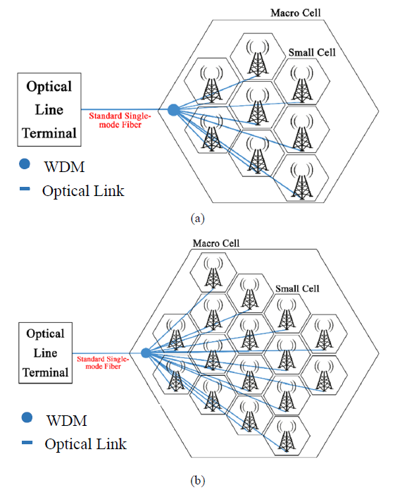 | Figure 3. Mobile fronthual for coherent WDM PON. (a) 8-small cell configuration. (b) 16-small cell configuration |
 of each WDM channel should not exceed 100 GSps since it is limited by the speed of the available electronics. To increase the transmission bit rate per channel (i.e., per wavelength)
  , one should go to higher-order QAM modulation supported by polarization multiplexing technique (i.e., DP transmission).(vi) The design should be issued first to support 600 Gbps per λ and then extended to support 1 Tbps per λ. These two values of
  are recommended by different research groups for future WDM-PONs serving 5G and B5G network services.Few remarks related to the aforementioned points are given the following (i) The total bit rate
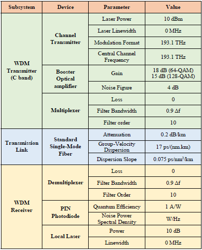
  served by the MFH link is computed from
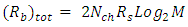 | (1) |
 | (2) |
 .(ii) To ensure zero intersymbol interference (ISI) at the input of the electrical decision circuit used in each channel receiver, the symbol pulse shape should have a raised-cosine filter (RCF) spectrum at the input of this circuit. The filter bandwidth (i.e., the symbol message electrical bandwidth) is given by
 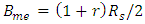 | (3) |
 ideal case (i.e., Nyquist filter) corresponds to r = 0, which gives an ideal lowpass filtering spectrum and leads to
  The other extreme is r = 1, which yields a full RCF spectrum having
  Note that when the symbols are used to modulate the optical carrier, the generated modulation optical signal has approximately an optical bandwidth
 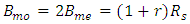 due to the generation of upper and lower sidebands.Consider the case of
  = 600 Gbps. The corresponding symbol rate
 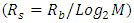 equals 50 and 42.9 GSps when 64- and 128-QAM formats are used, respectively. To prevent overlapping between neighboring channels at the optical demultiplexer output,
  should be less than
  . In other words, the following condition should be satisfied in the design of the demultiplexer
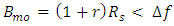 | (4a) |
 | (4b) |
 = 75 GHz from the WDM grid yields
  = 0.5 and 0.75 for 64- and 128-QAM formats, respectively. Note that one can choose
  = 100 GHz for the case of 64-QAM formats signaling to yield
  = 1 (i.e., full RCF) but the spectral efficiency reduces since it is inversely proportional to
  (see Eqn. 2).Now consider the second case of
  Tbps. The symbol rate
  equals to 83.3 and 71.4 GSps for 64- and 128-QAM formats. Choosing
  = 100 GHz yields
  = 0.2 and 0.4, respectively. One can go to
  = 125 GHz to relax the demultiplexer design while reducing the spectral efficiency to 80%. The corresponding
  which in this case is 0.6 and 0.75, respectively.
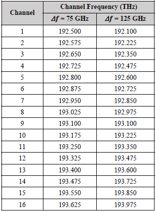
4. System Parameters Used to Produce the Simulation Results of the Designed WDM-PONs
- The results are presented in two scenarios corresponding to two data rates per channel, 600 and 1000 Gbps. Each scenario includes two main parameters, modulation format and number of channels. The simulation is executed using Optisystem software ver. 15.0. The maximum transmission length (i.e., maximum reach) is estimated when the bit error rate (BER) at the received side approaches
 This BER level corresponds to the BER threshold of 7% hard decision (HD) forward error correcting (FEC) code.The simulation results are presented for two coherent WDM-PONs operating with 600 and 1000 Gbps data rate per channel (i.e., per wavelength
  ). Each network is designed to support 8- and 16-antenna cells using either dual-polarization (DP) 64-QAM or 128-QAM signaling format. This yields eight PONs under observation. Each PON is labelled by three indices, namely
  -PON, where
 and
and  stand, respectively, for data rate in Gbps carried by a single WDM channel, order of the QAM format, and the number of WDM channels. Therefor
  takes the value of 600 or 1000, M takes the number 64 or 128, and
  is either 8 or 16. These PONs are also classified into two categories, A or B depending whether the data rate per channel is 600 or 1000 Gbps, respectively. AccordinglyClass-A PONs• PON-A1 ≡ (600, 64, 8) PON• PON-A2 ≡ (600, 128, 8) PON• PON-A3 ≡ (600, 64, 16) PON• PON-A4 ≡ (600, 128, 16) PONClass-B PONs• PON-B1 ≡ (1000, 64, 8) PON• PON-B2 ≡ (1000, 128, 8) PON• PON-B3 ≡ (1000, 64, 16) PON• PON-B4 ≡ (1000, 128, 16) PONFor comparison purposes, results related to a single-channel counterparts (i.e., Nch = 1) are also presented for both data rates and both signal formats.The frequencies of the WDM channels are selected in the C band (i.e., 1550nm region) according to International Telecommunication Union-Telecommunicate Standardization Sector (ITU-T) [25]. The ITU offers a frequency grid corresponding to frequency channel spacing
  of 25, 50, 75, ...GHz. The channel frequency matches the frequency of the unmodulated laser frequency used for this channel. The channel spacing should be selected to be equal to or less than the bandwidth of the modulated optical carrier
 | (5) |
 is the symbol rate,
  is the bit rate, M is the QAM order, and r is the roll-factor of the raised-cosine filter used for pulse shaping required to achieve zero intersymbol interference (ISI) at the input of the receiver decision circuit. For
  = 600 Gbps,
  = 50 and 42.86 GSps for 64- and 128-QAM signaling, respectively. Choosing
  = 75 GHz for this data rate requires that
  should be kept less than 0.5 and 0.75 for these formats, respectively. For 1 Tbps data rate networks,
  = 125 GHz is used for both M = 6 and 7 formatting where
  = 83.3 and 71.4 GSps, respectively. In this case
  should be chosen to be less than 0.5 and 0.75, respectively.From the previous discussion,
  = 0.2 is chosen in this work for the designed coherent WDM-PONs, which ensures that the bandwidth of the modulated optical carrier
  is within the corresponding
  and with enough frequency guard,
  , between the neighboring channels. For
  = 600 Gbps and
 = 60 and 51.4 GHz assuming 64- and 128-QAM, respectively. This design offers a frequency guard
  of 15 and 23.6 GHz, respectively. These values are to be compared with
  and 39.3 GHz for
  = 1 Tbps and
  = 0.2, respectively. Note, that in this case,
  = 100 GHz and 85.7 GHz for 64- and 128-QAM signaling, respectively.It is interesting to introduce a normalized frequency guard
  as a parameter to assess the overlapping degree between neighboring channels. For 600 Gbps and 1Tbps networks,
  = 0.2 and 0.32 for 64- and 128-QAM signaling, respectively. Note that
 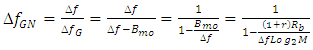 | (6) |
 channel. If the channel indices are labeled from 1 to
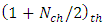
  , channel 5 and 9 correspond to the central channels for 8- and 16-channel WDM systems, respectively. The central channel frequency is set to 193.1 THz (i.e.,
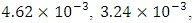
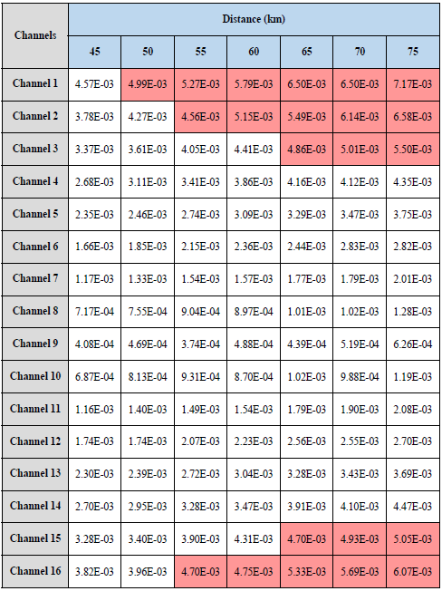
  = 1.554 nm) in the simulation. Table 1 lists the used channel frequencies for the 16-channel WDM system with
  = 75 and 125 GHz adapted for
  = 600 Gbps and 1 Tbps, respectively.
|
|
5. Simulation Results of 600 Gbps WDM-PONs
- This section presents simulation results related to coherent WDM-PONs operating with 600 Gbps per λ data rate. Results are presented for both 64- and 128-QAM signals and for two numbers of multiplexed channels,
 = 8 and 16. Results for a single-channel PON are also included for comparison purposes.
5.1. 8-Antenna 600 Gbps PON
- This subsection presents simulation results for 600 Gbps per λ PONs that use 8-channels WDM system. Two PONs are considered here depending on whether 64-QAM or 128-QAM signal format is used• PON-A1 ≡ (600, 64, 8) PON• PON-A2 ≡ (600, 128, 8) PONNote that the total data rate transmitted over the transmission link is 8 x 600 Gbps = 4.8 Tbps. A frequency channel spacing
 and roll-factor
  used in the simulation for both PONs are 75 GHz of 0.2, respectively. The following remarks are taken in the simulation.(i) Each demultiplexed channel at the receiver side uses its own DP DSP whose parameters are shared with other DSPs used for other demultiplexed channels (Fiber length, SSMF parameters, ...), but it has its own channel frequency.(ii) Each channel DSP is enabled to yield GVD compensation for the transmission link estimated at the operating channel frequency. Note that the GVD parameter D is varied slightly with the operating wavelength. All the receivers DSPs use D = 17 ps/(nm.km) and dispersion slope S = 0.075 ps/nm2/km at 1550 nm reference wavelength. These data are used by the DSP to estimate the GVD at the channel wavelength according to Eqn. (7).
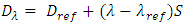 | (7) |
 is estimated when the BERs of all the channels do not exceed the threshold level of 4.6x10⁻³.
5.1.1. Simulation Results of (600, 64, 8) PON
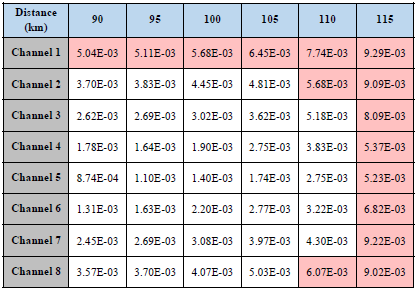
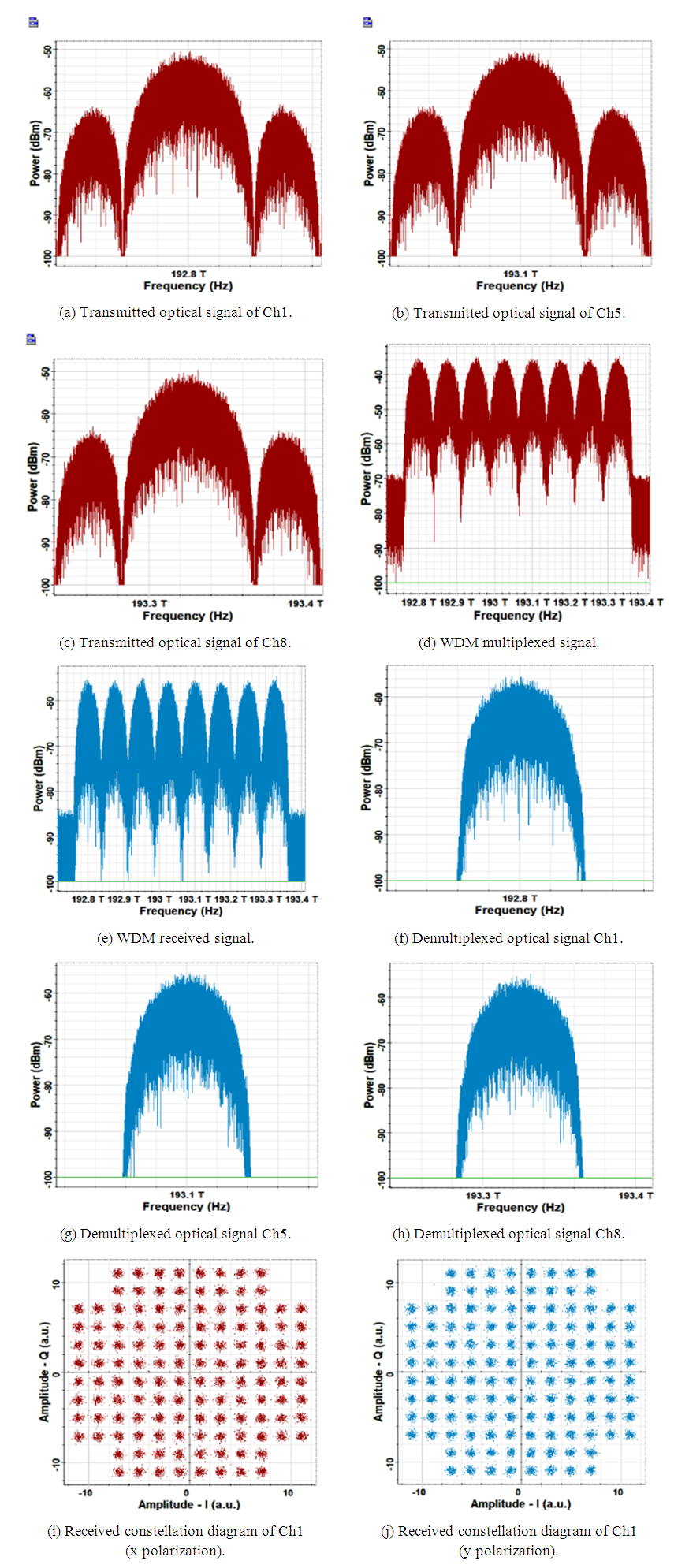
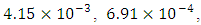
- PON-A1 uses 8-channels WDM system to transmit 600 Gbps DP 64-QAM signal per channel from the base station to the cell. The network is simulated and the results are shown in Fig. 4. Parts a-d show the spectrum of three transmitted channels (i.e., first channel Ch1, central channel Ch5, and last channel Ch8) along with the WDM multiplexed signal. The spectrum of the received WDM signal is given in part e of the figure, when the fiber length is set to 100 km which corresponds to the maximum reach. The spectrum and constellation diagrams corresponding to three demultiplexed signals (Ch1, Ch5, and Ch8) are illustrated in part (f, g, and h) and (i, j, and k), respectively. The BERs of these three channels are
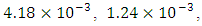 and
and  respectively; all BERs are less than BERth.
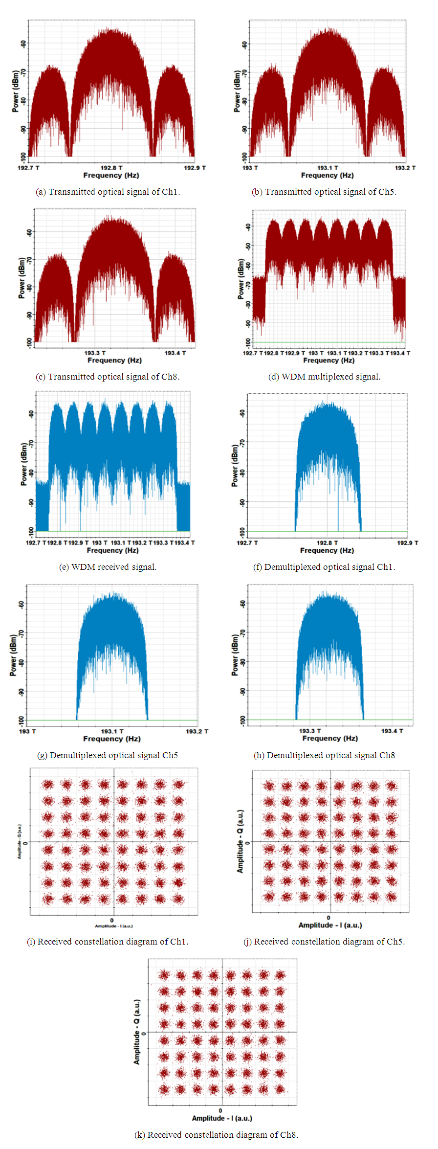 | Figure 4. Signals spectra and received constellation diagrams related (600, 64, 8) PON |
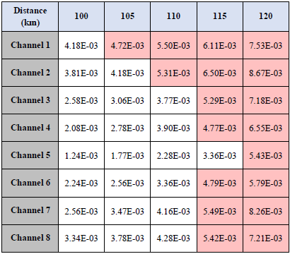
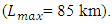
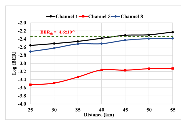
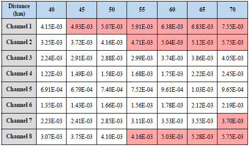
 Increasing L to 105 makes the BER of Ch1 (i.e., BER1) more than BERth. Therefore, the maximum reach is taken according to this channel. Increasing L further to 110 km makes, another channel (Ch2) not satisfy the required BER level. Note that PON-A1 can support the transmission to 8, 7, 6, and 1 antenna when L=100, 105, 110, and 115 km, respectively. At L= 120 km, the BERs of all the received channels are higher than BERth.
|
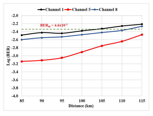 | Figure 5. Variation BERs of channels 1, 5, and 8 with a transmission distance for (600, 64, 8) PON |
5.1.2. Simulation Results of (600, 128, 8) PON
- The simulation is repeated for PON-A2 that uses 600 Gbps DP 128-QAM signal over 8-channels WDM system. The results are depicted in Figs. 6 and 7 and Table 4. The spectra of the signals at different points of the system are given in Fig. 6, along with the receiver constellation diagrams. The transmission length is set to the maximum reach
|
 | Figure 6. Signals spectra and received constellation diagrams related (600, 128, 8) PON |
 | Figure 7. Dependence of BERs of channels 1, 5, and 8 on transmission distance (600, 128, 8) PON |
5.2. 16-Antenna 600 Gbps PON
- This subsection presents simulation results for PON-A3 and PON-A4, which support 600 Gbps per λ data rate and 16-Channel WDM transmission under 64- and 128-QAM signaling, respectively.
5.2.1. Performance of (600, 64, 16) PON
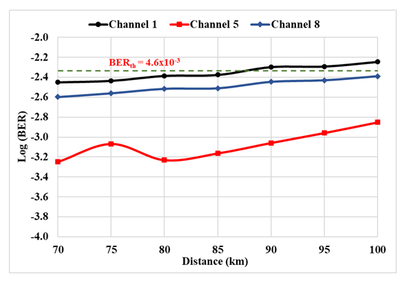
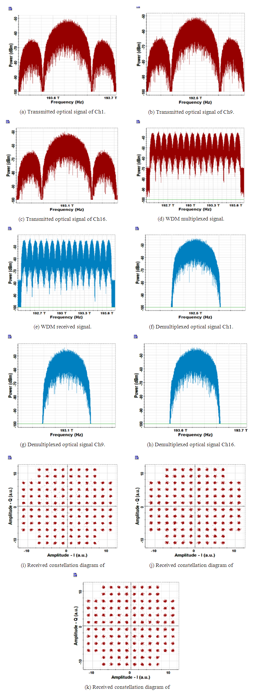
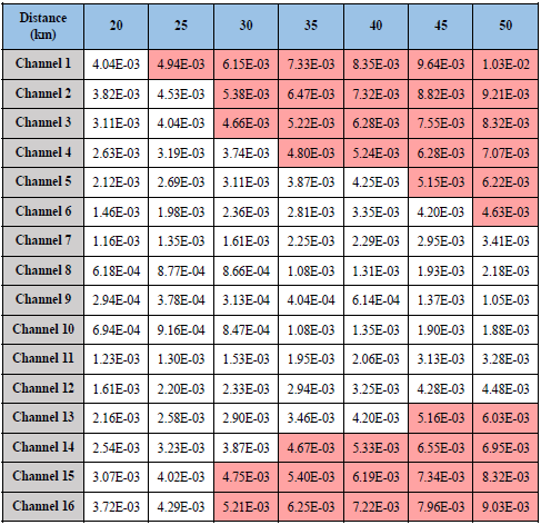
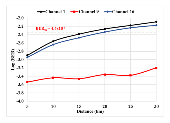
- PON-A3 is denoted by code (600, 64, 16) PON and its simulation results are depicted in Figs. 8 and 9 along with Table 5. The results in Fig. 8 are plotted for a transmission link length of 60 km corresponding to the maximum reach. The spectra of the Ch1, Ch9, and Ch16 are presented in this, assuming Ch9 is the central channel. The received BERs are
 and
and  for Ch1, Ch9, and Ch16, respectively.
|
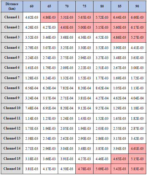
 | Figure 8. Signals spectra and received constellation diagrams related (600, 64, 16) PON |
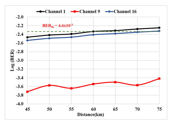 | Figure 9. BERs of channels 1, 5, and 8 versus transmission distance (600, 64, 16) PON |
5.2.2. Performance of (600, 128, 16) PON
- Simulation results related to PON-A4 are given in Fig. 10, Fig. 11, and Table 6. The maximum reach for this network is 45 km and determined by the behaving of Ch1. The signal spectra of three transmitted channels (Ch1, Ch9, and Ch16) at different points of the system are listed in Fig. 10. Also, the corresponding received constellation diagrams of (x polarization) are included.
|
 | Figure 10. Signals, spectra and received constellation diagrams related (600, 128, 16) PON |
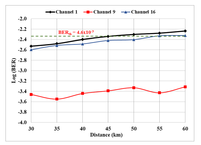 | Figure 11. BERs of channels 1, 9, and 16 versus transmission distance (600, 128, 16) PON |
 .
.6. Simulation Results of 1000 Gbps WDM-PONs
- In this section, simulation results of coherent WDM-PONs operating with 1000 Gbps per λ data rate are given. In addition, the results include two QAM signals, 64 and 128, and for two multiplexed channels, Nch = 8 and 16. Moreover, to prove the performance, a single-channel PON is involved.
6.1. 8-Antenna 1 Tbps PON
- In this subsection, the results for 1000 Gbps per λ PONs and 8-channels WDM system are presented for the following cases• PON-B1 ≡ (1000, 64, 8) PON• PON-B2 ≡ (1000, 128, 8) PONThe total transmission data rate over the link is 8 × 1000 Gbps = 8 Tbps. For both PONs, the frequency channel spacing and roll-factor utilized in the following simulation are 125 GHz and 0.2, respectively. Note that the received BERs of all the WDM channels are kept under observation during the simulation. The maximum reach (
 ) is estimated when all the channels BERs do not exceed the threshold level of
  .
.6.1.1. Simulation Results of (1000, 6, 8) PON
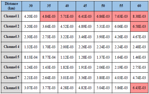
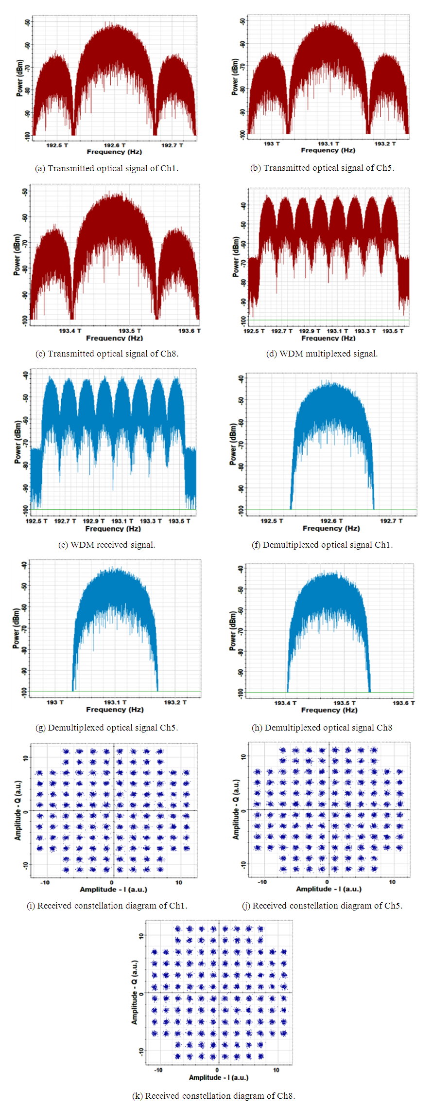
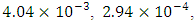
- PON-B1 utilizes 8-channels WDM system to transmit 1000 Gbps DP 64-QAM signal per channel from the base station to the cell. Figure 12 shows the results of the simulation. Parts a-d of this figure depicts the spectrum of three transmitted channels (i.e., first channel Ch1, central channel Ch5, and last channel Ch8) along with the WDM multiplexed signal. In addition, part e shows the spectrum of received WDM signal when the fiber length is set to 40 km, which corresponds to maximum reach. The spectrum and constellation diagrams corresponding to three demultiplexed signals (Ch1, Ch5, and Ch8) are illustrated in parts (f, g, and h) and (i, j, and k) of the figure, respectively. The BERs of these three channels are
 and
and  respectively; all BERs are less than BERth.
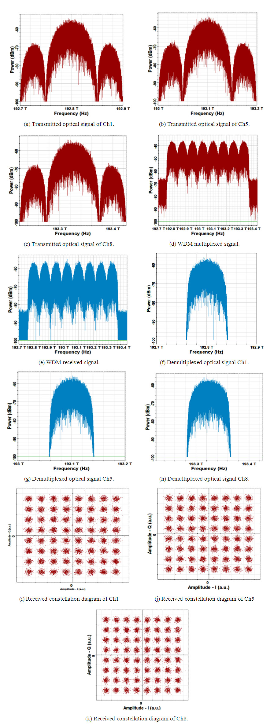 | Figure 12. Signals spectra and received constellation diagram related (1000, 64, 8) PON |
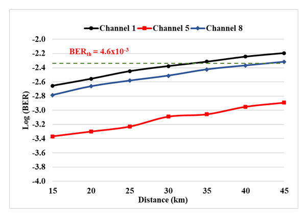
 | Figure 13. BERs of channels 1, 5, and 8 with transmission distance FOR (1000, 64, 8) PON |

 . Increasing L to 45 km makes the BER of channel 1 (i.e., BER1) more than BERth. Therefore, the maximum reach of 40 km is taken for this network. Increasing L further to 55 km makes another channel (Ch2) does not satisfy the required BER level. At L= 70 km, the BERs of channels 3 to 6 are less than the
  .
.
|
6.1.2. Simulation Results of (1000, 128, 8) PON
- The simulation is repeated for PON-B2 that uses 1000 Gbps DP 128-QAM signal over 8-channels WDM system. Figures 14 and 15 and Table 8 depict the obtained results. Figure 14 shows the spectra of the signals at different points of the system, along with the receiver constellation diagrams. The transmission length is set to the maximum reach


|
 | Figure 14. Signals spectra and received constellation diagram related (1000, 128, 8) PON |
 | Figure 15. Varitation of BERs of channels 1, 5, and 8 with a transmission distance of (1000, 128, 8) PON |
6.2. 16-Antenna 1 Tbps PON
- This subsection presents the results of simulation for 1000 Gbps per λ data rate and 16-channel WDM transmission assuming 64- and 128-QAM signaling represented by PON-B3 and PON-B4, respectively.
6.2.1. Simulation Results of (1000, 6, 16) PON
- Figures 16 and 17 along with Table 9 depict the simulation results for PON-B3, which is denoted by code (1000, 64, 16) PON. Figure 16 shows the results corresponding to transmission link length of 20 km (maximum reach). The spectra of the Ch1, Ch9, and Ch16 are presented in this figure, assuming Ch9 is the central channel. The received BERs are
 and
and  for Ch1, Ch9, and Ch16, respectively.
|
 | Figure 16. Signals spectra and received constellation diagram related (1000, 64, 16) PON |
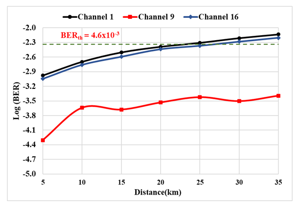 | Figure 17. Variation of BER with a transmission distance of Ch1, Ch9, and Ch16 of (1000, 64, 16) PON |
6.2.2. Simulation Results of (1000, 128, 16) PON
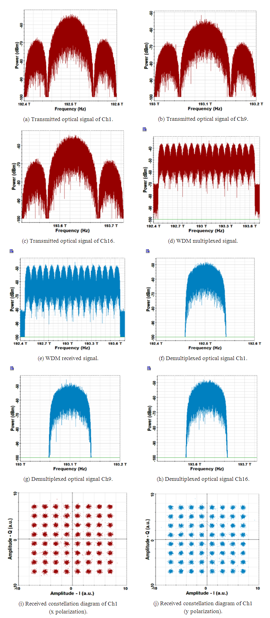
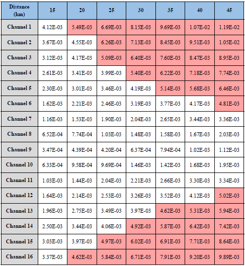
- Simulation results of PON-B4, which is denoted by code (1000, 128, 16) PON are depicted in Figs. 18 and 19 and Table 10. The corresponding maximum reach of transmission link length is 15 km. The spectra and constellation diagram results are plotted in Fig. 18 for a 15 km transmission distance. The spectra of the Ch1, Ch9, and Ch16 are also presented in this figure, assuming Ch9 is the central channel. The received BERs for three channels Ch1, Ch9, and Ch16 are 4.12 x10⁻³, 3.47 x10⁻⁴, and 3.37 x10⁻³, respectively.
|
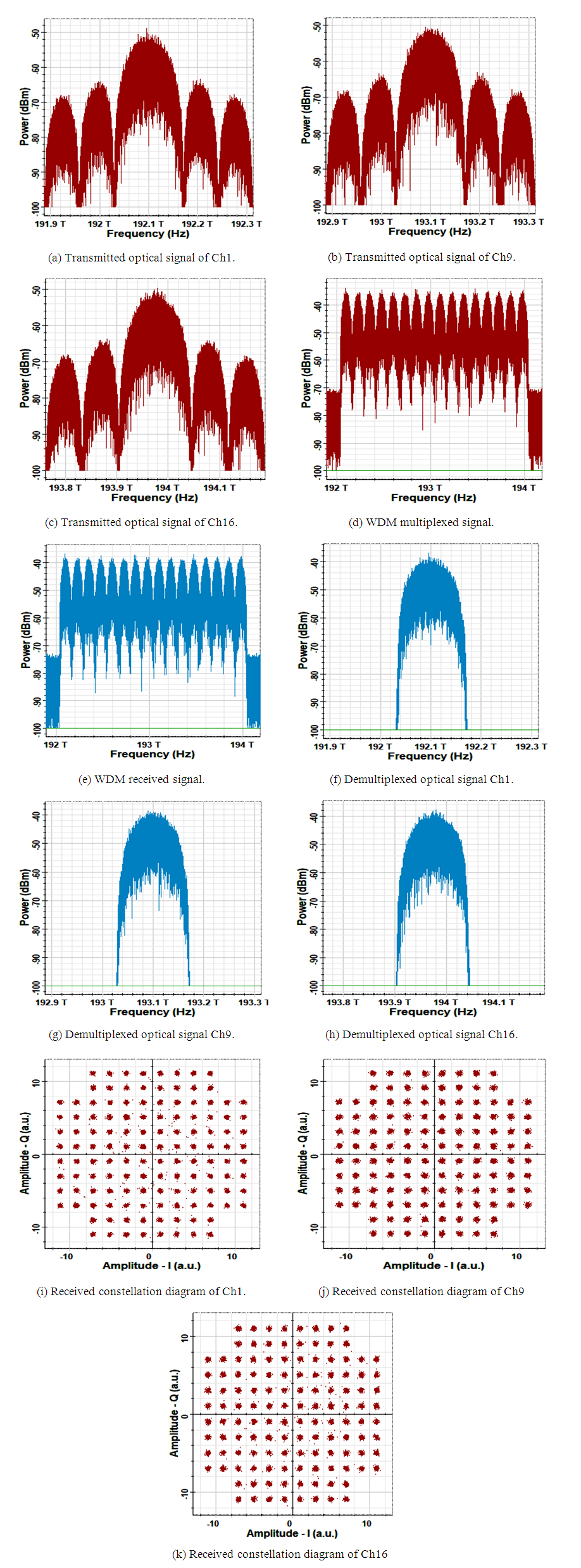 | Figure 18. Signals spectra and received constellation diagram of (1000, 128, 16) PON |
 | Figure 19. BER variation with a transmission distance of Ch1, Ch9, and Ch16 of (1000, 128, 16) PON |
 . Increasing L to 20 km makes the BER of channel 1 and channel 16 more than BERth. Increasing L further to 25 km makes other channels (Ch2, Ch3, and Ch15) not satisfy the required BER level. At L= 45 km, the BERs of channels 7 to 11 are only less than the BERth.
7. Performance Comparison
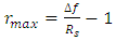
- This section presents a brief performance comparison for the PONs investigated in this chapter. The performance measure used for comparison purpose is the maximum reach
 corresponding to
  of
of  . Recall that the PONs have been investigated for two modulation formats (64- and 128-QAM), two numbers of multiplexed WDM channels
  (600 Gbps and 1 Tbps).Figures 20a and b show chart bars corresponding to
  as a function Nch and modulated formats assuming 600 Gbps and 1 Tbps data rate per channel, respectively.
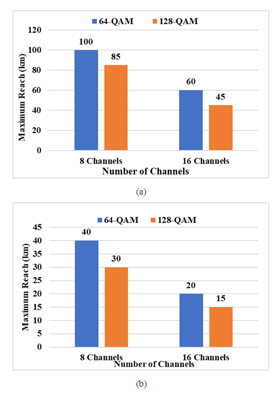 | Figure 20. Variation of maximum reach with the number of channels.  |
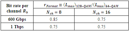
 which is denoted here by the parameter
  The results are given for different values of
  and
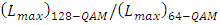
and  . Note that going from 64-QAM to 128-QAM signaling yields
  . This indicates that the maximum reach reduces to 75%.
|
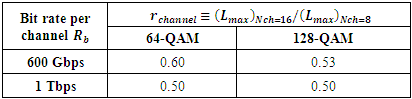
 as depicted in Table 12. According to this table, one can say 16-cahnnel PON reduces
  to about 50% of the 8 channels PON.
|
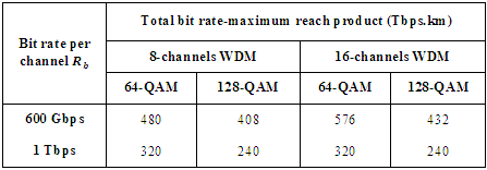
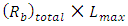 and denoted here by the parameter "BLP". Note that
 The results corresponding to this parameter is given in Table 13 investigating the results in this table highlights the following findings (i) Operating with
  = 600 Gbps offers higher BLP compared with
  = 1 Tbps assuming the same number of WDM channels and modulation format.(ii) Higher BLP is achieved when the PON is designed with 64-QAM signaling rather than the 128-QAM signaling.(iii) For fixed
  and modulation format, the 16-channel PON offers higher BLP compared with 8-channels PON.(iv) The highest BLP is 576 Tbps.km, which is achieved in a PON designed with Nch = 16,
  =600 Gbps, and 64-QAM format.
|
8. Conclusions
- The transmission performance of coherent WDM-PON has been investigated to support 5G and B5G service distribution. The PON sends (receives) the data to (from) a macro cell consisting of 8 or 16 small cells; each small cell uses one of the WDM wavelength. 64- and 128-QAM signaling have been used to support data rate transmission
 of 600 Gbps and 1 Tbps per single wavelength. Simulation results based on Optisystem software ver. 15.0 have been obtained to determine the maximum reach
  for each WDM-PON designed in this work. The main conclusions drawn from this study are(i) WDM channel spacing
  of 75 and 125 GHz is suitable to transmit 600 Gbps and 1 Tbps data rate,
  to each small cell, respectively. These values of
  are applicable for both DP 64- and 128-QAM signaling.(ii) Adapting the parameters of each channel receiver DSP makes the DSP capable to compensate the effect of fiber dispersion on the channel performance. This statement is valid for both values of
  600 Gbps and 1 Tbps, and for both modulation formats.(iii) When both
  and the number of WDM channels Nch are kept fixed, the use of 128-QAM format rather than 64-QAM format reduces the maximum reach to approximately 75%. For example, when
  = 600 Gbps and Nch = 16,
  reduces from 60 to 45 km when 128-QAM signaling is used in place of 64-QAM. These values of
  are to be compared with 20 and 15 km, respectively, when
  Tbps.(iv) When both modulation format and
  are kept constant, the maximum reach reduces by 50% approximately when the WDM-PON is designed to serve 16-small cells configuration rather than 8-small cell configuration. For example, using 64-QAM signaling and
  = 600 Gbps yields
  = 100 and 60 km when Nch = 8 and 16, respectively. These values are to be compared with
  = 85 and 45 km, respectively when 128-QAM signaling is used.(v) Going from
  = 600 Gbps to 1 Tbps reduces
  to approximately the third. Using Nch = 16 and 64-QAM signaling yields
  = 60 and 20 km when
  = 600 Gbps and 1 Tbps respectively. If 128-QAM signaling is used,
  = 45 and 15 km, respectively.(vi) The DP 64-QAM modulation formats can support 1 Tbps transmission if the symbol rate
  of 84 GSps is used. If extra is transmitted as a header, one can go to 128-QAM signaling at the same value of
  . this yields 1/7
  header.(vii) Higher bit rate-length product (BLP) is obtained when one uses
  = 600 Gbps rather than 1 Tbps, 64-QAM rather the 1280-QAM, and
  = 16 rather than 8. The highest value of BLP is 576 Tbps.km which is achieved in a PON designed with
  = 16,
= 16,  = 600 Gbps, and DP 64-QAM format.