-
Paper Information
- Paper Submission
-
Journal Information
- About This Journal
- Editorial Board
- Current Issue
- Archive
- Author Guidelines
- Contact Us
International Journal of Networks and Communications
p-ISSN: 2168-4936 e-ISSN: 2168-4944
2020; 10(2): 33-40
doi:10.5923/j.ijnc.20201002.01
Received: July 20, 2020; Accepted: August 4, 2020; Published: August 15, 2020

Towards Optical Frequency Comb-Based High-Capacity Superchannel Transmission-Part II: Transmission Performance
 Abstract
 Reference
 Full-Text PDF
 Full-text HTML
Adnan A. Abdullah 1, Raad S. Fyath 2
1Department of Electronic and Communications Engineering, Al-Nahrain University, Baghdad, Iraq
2Department of Computer Engineering, Al-Nahrain University, Baghdad, Iraq
Correspondence to: Raad S. Fyath , Department of Computer Engineering, Al-Nahrain University, Baghdad, Iraq.
| Email: |  |
Copyright © 2020 The Author(s). Published by Scientific & Academic Publishing.
This work is licensed under the Creative Commons Attribution International License (CC BY).
http://creativecommons.org/licenses/by/4.0/

The proposed comb reported in the accompanying paper (Part I) is used in wavelength-division multiplexing (WDM) superchannels operating with 160 and 320 Gbps polarization multiplexing (PM)-16QAM signal per comb line. The transmission performance of these superchannel communication systems is investigated using Optisystem ver. 15.0 software. The investigation is extended further to design a pilot-assisted receiver local comb operates synchronously with the transmitter comb. The results reveal that the best figure-of-merit (FoM) for superchannal designed with 25 GHz channel spacing and 160 Gbps PM-16QAM signaling is 5120 Tbps.km when 64 comb lines are used.
Keywords: Comb-based superchannel transmission, Polarization multiplexing, 16 Quadrature amplitude modulation
Cite this paper: Adnan A. Abdullah , Raad S. Fyath , Towards Optical Frequency Comb-Based High-Capacity Superchannel Transmission-Part II: Transmission Performance, International Journal of Networks and Communications, Vol. 10 No. 2, 2020, pp. 33-40. doi: 10.5923/j.ijnc.20201002.01.
Article Outline
1. Introduction
- Recently, there is increasing interest in high-capacity WDM communication systems using optical comb-based superchannel transmission [1-5]. This paper investigates the transmission performance of Tbps superchannel communication systems incorporating the optical frequency comb generator (OFCG) proposed in the accompanying paper [1] and used here as a C-band WDM source [6-16]. The investigations are based on a series of transmission simulations using two different comb frequency spacings,
 = 25 and 50 GHz, and polarization multiplexing-16 quadrature amplitude modulation (PM-16QAM). The maximum achieved transmission distances are recorded when the received BER approaches the BER threshold level BER=
  . This threshold corresponds to 7% overhead hard decision (HD) FEC code frequently and it is usually assumed in the simulation of optical networks and optical communication systems. This code uses 7%-bit redundancy and yields a
  BER when the precoded
 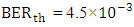 . The PM-16QAM signaling is used for of each single comb line (channel). Two bit rates
  per channel, 160 and 320 Gbps, are used in this simulations when
  = 25 and 50 GHz, respectively. Simulation results are obtained using Optisystem ver.15.0 software. Unless otherwise stated, the parameter values of the superchannel system are given in Table 1. The rest of the paper is organized as follows. Section 2 introduces the configuration of the comb-based superchannel transmission system. Design issues and performance evaluation of WDM superchannels operating with 160 and 320 Gbps line data rates are given in Sections 3 and 4, respectively. Section 5 gives feasibility study for regeneration of Com Lines at the Receiver Side Using a Single-Pilot Tone. The concluding remarks are given in Section 6.
|
2. Transmission System Configuration
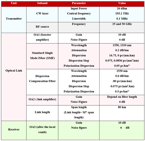
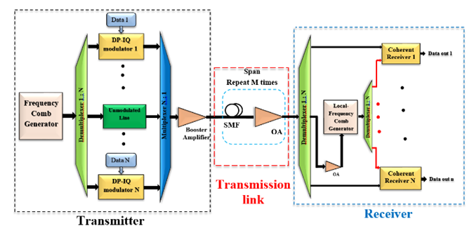
- The configuration of the PM-16QAM superchannel transmission system using the proposed OFCG is depicted in Fig. 1. The configuration consists of three subsystems which are superchannel optical transmitter, transmission link, and superchannel optical receiver.
2.1. Transmitter Side
- The transmitter side comprises of the proposed OFCG, optical demultiplexer, PM-16QAM modulators, and optical demultiplexer as illustrated in Fig. 1. The OFCG generates frequency comb lines with various flatness ranges. Number of these comb lines (N) are split by the demultiplexer and then applied to the external optical modulators. These comb lines act as unmodulated optical carriers are individually modulated by PM-16QAM modulators. The first stage of PM-16QAM modulator is polarization splitter, where each unmodulated comb line is split into two polarization waveforms (X-polarization and Y-polarization). Each waveform is divide into two orthogonal components, in phase (I-component) and quadrature phase (Q-component).
 | Figure 1. Block diagram of the simulated OFCG-based superchannel of PM-MQAM transmission system |
2.2. Transmission Link
- The transmission link consists of M spans and each span contains a single-mode fiber (SMF) followed by an optical amplifier (OA) to compensate its power losses. In this work, the single span uses 80 km SMF and the OA gain is calculate from the following formula
 where
where  is the gain of the optical amplifier,
  is the attenuation factor of the SMF at 1550 nm which equal to 0.2 dB/km, and
  is the length of SMF. Therefore, for this span length, the corresponding OA gain
  = 0.2 dB/km × 80 km = 16 dB, and this span can be repeated M times.
2.3. Receiver Side
- At the receiver side, the received superchannel is separated into N modulated channels by using 1: N demultiplexer, and each received channel is treated independently. The data is extracted from each demultiplexed channel using digital signal processing (DSP)-based coherent PM-QAM demodulator. The used digital signal processing performs DSP steps required in coherent single-carrier communication systems utilizing dual-polarization modulation formats as illustrated in Fig. 2b. A local comb generator is used at the receiver side to generate all the required local oscillators (LOs) instead of using an independent laser for each received channel. The receiver local comb is identical to that used in the transmitter side and operates synchronously with it.
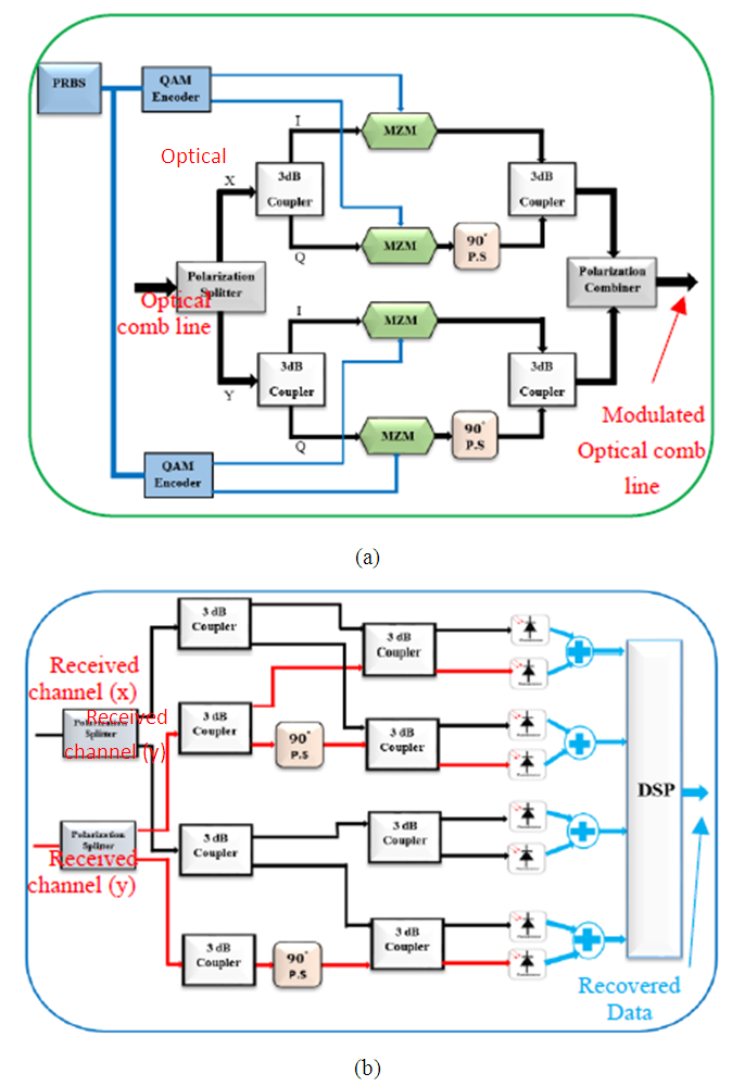 | Figure 2. Modulation and demodulation stages (a) PM-16QAM modulation stage (b) PM-16QAM coherent receiver stage |
3. Design Issues and Performance Evaluation of N×160 Gbps Superchannels
- This section presents design concepts and performance investigation of Tbps superchannel transmission using 25 GHz channel frequency spacing. Each single channel of the WDM system is modulated with 160 Gbps PM-16QAM signaling. Simulation results are reported for number of superchannels generated by the proposed OFCG using different number of WDM channels (16, 32, 48, 64, 72, and 80) with frequency spacing of 25 GHz. The maximum reached distance
 is recorded for different operating parametrs. Before implementing these investigations there are some design issues should be stated for the superchannel under investigation.
3.1. Design Issues
- i. Selecting the Booster Amplifier GainIn order to find the optimum value of the booster amplifier gain which yields the minimum BER, the first step is to investigate the performance of back-to-back (B2B) transmission of a superchannel (for example, carrying 64 WDM channels). When the booster amplifier gain increases to 8 dB, the BERs of all the WDM channels become less than the threshold value. The second step is to investigate the performance of this superchannel for the case of 6-span transmission. The booster amplifier gain is varied from 0 to 25 dB and the received BER is recorded. Three channels (channel 1, channel 33, and channel 64) are monitored by BER tester to examine the BER behaviour for these channels. Figure 3 displays the behaviour of the three channels and the optimum value of booster amplifier gain which is selected. This figure shows that the best value of the booster amplifier gain is 10 dB. The same result is obtained when simulation tests are performed for superchannels designed with other numbers of multiplexed channels. Therefore, all the following investigations will use this amplifier gain value.
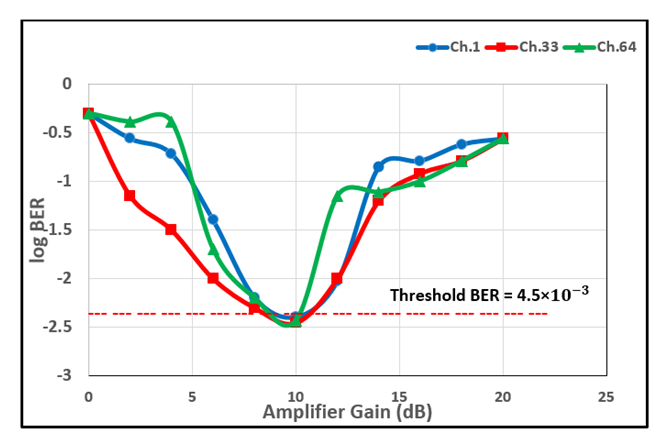 | Figure 3. Variation of BER with booster amplifier gain for 6-span 64-channel system |
 for each PM-16QAM channel carrying 160 Gbps -bit rate
  can be calculated as follows. The single polarization channel bit rate is 80 Gbps. For a QAM modulation format dealing with M symbol,
 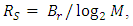 where M is the number of symbols. This number can be expressed as
  , where m is the number of bits pre symbol. In a single polarized 16QAM signaling, M = 16 symbols and m = 4 bits. Therefore,
  = 10 Gsymbol/s, and
  for polarized multiplexing is 20 Gsymbol/s. The electrical modulated signal (
 ) and optical modulated channel bandwidth
  are calculated using eqns. (1) and (2), respectively.
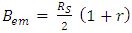 | (1) |
 | (2) |
 should be less than the channel spacing
  to prevent the crosstalk between the receiver adjacent demultiplexed channels at the receiver side. From eqn. (2), can be calculated as
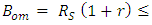
 and
and  Gbps given that
  should be used in the design. In this work r = 0.2 is used. Therefore, the optical bandpass spectrum equivalent to
  be 24 GHz as shown in Fig. 4. When r is varied from 0.05 to 0.25 with step of 0.05 the corresponding suitable
  values are 21, 22, 23, 24, and 25, respectively, for
  160 Gbps and
  = 20 Symbol/s.
 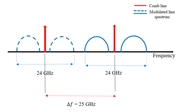 | Figure 4. Optical channel bandwidth corresponding to r = 0.2 |
3.2. Superchannel Simulation Results
- This subsection presents the spectra and the receiver constellation diagrams of the superchannel (80 channels). Simulation results are presented in Fig. 5 for the case corresponding to a transmission length L=
 = 140 km (1 span + 60 km). Channel 1 is kept under the observation since it shows the worst case performance among the channels. Figure 5a depicts the spectrum of the unmodulated comb line number one (192.1 THz). This signal is separated into two polarized signals X and Y, and only X-components is displayed. The QAM pulse generator used to modulate this signal has the spectrum of RF signal shows in Fig. 5b. This spectrum has a baseband component covers the range of frequencies from 0-20 GHz, where the 20 GHz relates to the symbol rate (
 = 20 Gsymbol/s). The spectrum moreover contains high frequency components covering the range beyond 20 GHz. The I-phase optical component represents the output of the QAM modulator, see Fig. 5c, and the PM-16QAM modulated signal spectrum is displayed in Fig. 5d. After transmission the modulated signal over the fiber link, it is received at the demultiplexer output and its spectrum appears as in Fig. 5e. Figure 5f illustrates the spectrum of the amplified photogenerated current waveform which has a single-sideband spectrum of 12 GHz bandwidth. The constellation diagram (X-side) at the QAM demodulator output is demonstrated in Fig. 5g and shows clearly the existence of random phase effect, which arises from the fiber dispersion. The influence of dispersion is compensated by using DSP, which results a clear 16-QAM constellation diagram (X-side) as illustrated in Fig. 5h. When this superchannel is transmitted over the SMF, the fiber nonlinearity due to Kerr effect influences its spectrum as depicted in Fig. 5i. This point becomes clear when the fiber nonlinearity parameter is tuned OFF in the simulation software see (Fig. 5j). Zoomed spectra are inserted here to display the effect of nonlinearity as displayed in Figs. 5k and 5l.
  | Figure 5. Spectra and constellation diagrams for channel one in a superchannel communication system operating with 160 Gbps, 80-WDM channels, PM-16QAM and L=  = 140 km. (a) Unmodulated comb line (192.1 THz). (b) Output spectrum of the QAM pulse generator (I-phase component). (c) Optical spectrum of the optical modulator for the I-component. (d) PM-16QAM modulated channel spectrum. (e) Received channel spectrum beyond the demultiplexer. (f) Amplified photocurrent electrical spectrum. (g) X-component Constellation diagram at the DSP input. (h) X-component constellation diagram at the DSP output. (i) 80 channels spectrum at the end of the transmission link when the nonlinearity is affected. (j) 80 Channels spectrum at the end of the transmission link when the nonlinearity is not affected. (k) Zoomed spectrum when the nonlinearity is affected. (l) Zoomed spectrum when the nonlinearity is not affected = 140 km. (a) Unmodulated comb line (192.1 THz). (b) Output spectrum of the QAM pulse generator (I-phase component). (c) Optical spectrum of the optical modulator for the I-component. (d) PM-16QAM modulated channel spectrum. (e) Received channel spectrum beyond the demultiplexer. (f) Amplified photocurrent electrical spectrum. (g) X-component Constellation diagram at the DSP input. (h) X-component constellation diagram at the DSP output. (i) 80 channels spectrum at the end of the transmission link when the nonlinearity is affected. (j) 80 Channels spectrum at the end of the transmission link when the nonlinearity is not affected. (k) Zoomed spectrum when the nonlinearity is affected. (l) Zoomed spectrum when the nonlinearity is not affected |
 Figure 6 illustrates this influence when using 160 Gbps PM-16QAM signaling. The results are
  = 1040 km (13 spans) and
  =140 km (1 span + 60 km) when N=1 and 80, respectively.
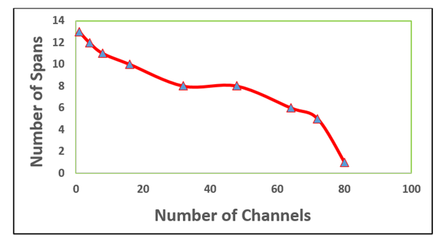 | Figure 6. Variation of maximum reach measured by number of 80 km –span with number of multiplexed channels |
3.3. Comparison Between Superchannel and Conventional WDM System
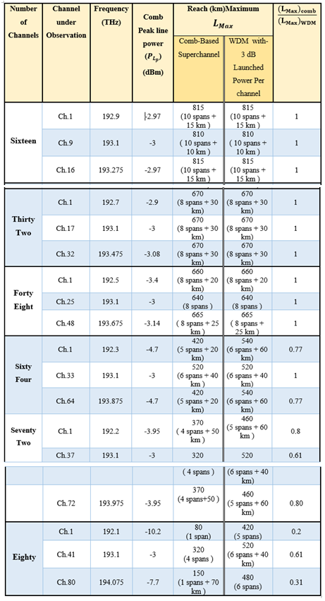
- Different superchannels designed with (16, 32, 48, 64, 72, and 80) aggregated channels and 25 GHz frequency spacing are considered here. The performance of these superchannel, measured by the maximum reach
 is investigated and compared with that of the conventional WDM counter parts and the results are summarized in Table 2. Three channels are kept under observation, namely the first, central, and the last ones. The performance of these superchannels depends on the position on the spectrum flatness ranges. When the superchannels locate around 1-dB flatness range,
  is nearly the same for both systems. This is true when the superchannel contains 16, 32, and 48 channels. Superchannels based on 64, 72, and 80 channels have less transmission performance than WDM system. The reduction in superchannel
  compared with WDM system occurs because the powers of the comb lines gradually decrease at the both ends of the comb line spectrum, while the WDM system is simulated under constant channel laser power.
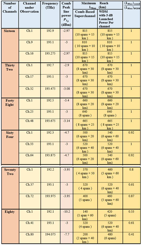
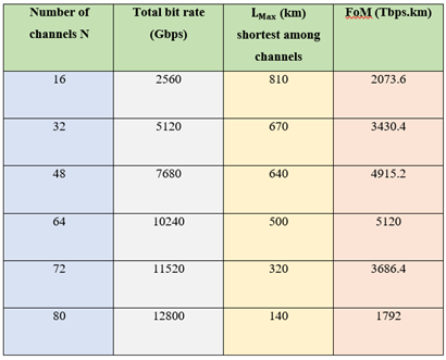
3.4. Figure of Merit (FoM)
- In order to make performance comparison among these superchannels, a figure of merit (FoM) should be introduced to take into account depending on the number of multiplexed channels N, bit rate
 and the maximum distance
  The following equation is proposed in this work to estimate the FoM
 | (3) |
 is the shortest maximum reach among the multiplexed channels. Table 3 lists the FoM for each superchannel evaluated by applying eqn. (3) with
  = 160 Gbps. Investigating the results in this table reveals that 64-line superchannel gives the best transmission performance and it can be used to transmit 10.24 Tbps data over 500km transmission link.
|
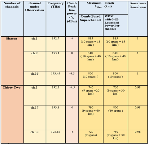
4. Transmission Performance of N×320 Gbps Superchannels
- This section presents simulation results for two superchannels based on the proposed OFCG and designed with N=16 and 32 channels having 50 GHz channel spacing. Each channel carries 320 Gbps PM-16QAM signal. Accordingly, the symbol rate
 = 40 Symbol/s. Using r= 0.2 yields an optical channel bandwidth = 48 GHz
 = 50 GHz. The maximum reach
  is recorded from the simulation tests and compared with that of the conventional WDM system. The booster amplifier gain is set to 10 dB which is the optimum gain obtained by simulating the 32- line superchannel when L =
  =720 km (9 spans).Table 4 compares the maximum reach for 16-and 32-line superchannels with those obtained from conventional WDM counterparts. Three channel are kept under observation, first channel, central channel, and last channel. The results reveals that designing the superchannel with 16 channels gives almost the same maximum reach achieved by the corresponding WDM system. This result is expected since the sixteen comb lines have around 1-dB flatness. In contrast, superchannel system implemented with 32 channels gives shorter maximum reach
  compared with the conventional WDM system. Recall that the line power generally decreases as the frequency position of the line moves away from comb spectrum. Figure 7 shows the BER performance of channels 1, 9, and 16 as a function of number of spans for a superchannel designed with N= 16 channels. The receiver constellation diagrams related to these three channels are also depicted in this figure for L =
  = 815, 840, and 800 km for channels 1, 9, and 16, respectively. Table 5 lists the FoM for the two superchannels as estimated by applying eqn. (3). Note that the 32-line superchannel gives better F-o-M, it is capable of transmission 10.24 Tbps over transmission link length of 720 km.
|
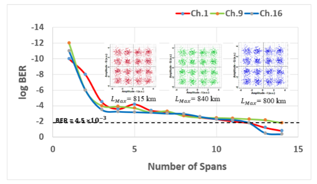 | Figure 7. BER Performance of the 16-line superchannel as a function of number of transmission spans. The insert shows the receiver constellation diagrams corresponding to L =  of each channel. of each channel. |
|
 = 50 GHz
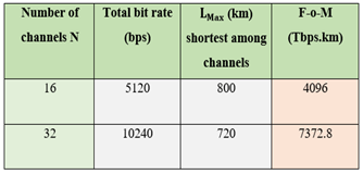
5. Regeneration of Com Lines at the Receiver Side Using a Single-Pilot Tone
- To overcome performance penalties due to laser frequency offset between the transmitter OFCG and the local OFCG and to decrease the complexity of the DSP at the receiver, one of the comb lines is filtered at the transmitter side and sent without modulation. This unmodulated line is called a pilot tone. The phase locking and the stable frequency spacing properties of the comb source offer the ability to regenerate the comb lines at the receiver side by using this pilot tone. In this work, the 193.1 THz optical line is considered as the pilot tone as shown in Fig. 8. In the following investigations, 25 GHz frequency spacing and 160 Gbps PM-16QAM channel signaling are used.
 | Figure 8. Designed scheme of a synchronous local OFCG using a single-pilot tone |
5.1. Superchannel Transmission Performance Investigation
- Table 6 lists the transmission performance of superchannels designed with different channels (16, 32, 48, 64, 72, and 80) and implemented using local OFC comb lines generated using 193.1 THz single-pilot tone scheme. The maximum reach
 of these superchannels are compared with that of corresponding WDM systems. Table 6 reveals the superchannels have acceptance values of
  compared with the WDM counterparts and these superchannels gives nearly 1 span of
  penalty compared with conventional superchannels (see Table 1).
|
5.2. Superchannel Simulation Results
- This subsection present simulation results for 64-line superchannel designed with
 = 25 GHz,
  = 160 Gbps, and PM-16QAM signaling. Figure 9a illustrates the transmission spectrum which contains 63 modulated channels and one unmodulated channel used as the single-pilot tone. The pilot tone is demultiplexed at the receiver side and then amplified by 10 dB optical amplifier. The spectrum of the amplified pilot tone filtered at the receiver side is shown in Fig. 9b. The regenerated OFCG spectrum is displayed in Fig. 9c where this spectrum is similar to the OFCG spectrum at the transmitter side.
 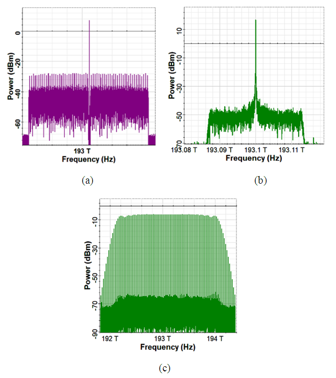 | Figure 9. Superchannel spectra of 64-channel transmission system using single-tone pilot assisted local OFCG. (a) Transmitter output which consists of 63 modulated channels and one unmodulated pilot tone. (b) Amplified 193.1 THz tone filtered at the receiver side. (c) Pilot-local assisted OFCG |
6. Conclusions
- Two sets of superchannels have been designed using the proposed OFCG. The first set uses 25 GHz spacing comb and 160 Gbps PM-16QAM line signaling. These superchannels contains 16, 32, 48, 64, 72, and 80 modulated comb lines. The second set of the superchannels are generated based on 50 GHz frequency spacing comb and 320 Gbps PM-16QAM line signaling, where 16 and 32 modulated lines have been used in this scheme. The proposed figure-of-merit equation
 has been used to reveal the best transmission performance among the superchannels. For the first set of superchannels, the best performance has been achieved when the superchannel carries 64 channels, it has a F-o-M = 5120 Tbps.km (i.e., can be used to transmit 10.24 Tbps data over 500km transmission link). The best performance of the second set of superchannels has been achieved when 32 channels are used. This superchannel has F-o-M = 7372.8 Tbps (i.e., it is capable of transmission 10.24 Tbps over transmission link length of 720 km). Nearly the same transmission performance of the superchannels are obtained when one of the unmodulated comb line at the transmitter side has been used as pilot signal to regenerate a local comb at the receiver side. In this way, simplified and perfect synchronization scheme has been obtained between the transmitter and receiver combs.The work in this paper can be extended in the future to address the performance of the hybrid WDM/TDM comb-based superchannel transmission. The proposed OFCG can be redesigned and reconfigured to yield 100 GHz line spacing with of lines suitable for WDM superchannel.
Appendix
References
| [1] | B. Corcoran, M. Tan, X. Xu, A. Boes, J. Wu, T. Nguyen, S. Chu, B. Little, R. Morandotti, A. Mitchell, and D. Moss, “Ultra-dense optical data transmission over standard fiber with a single chip source”, Nature Communications, vol. 11, Article no. 2568, May 2020. |
| [2] | N. Deng, W. Wei, Z. Liu, W. Xie, and Y. Dong, “Distribution of optical-comb-based multi-frequency microwave signals over 100 km optical fiber with high phase stability”, Optics Express, vol. 28, no. 11, pp. 16634-16643, 2020. |
| [3] | P. M. Palomo, J. N. Kamel, T. J. Kippenberg, W. Freude, S. Randel, C. Koos, “Performance of chip-scale optical frequency comb generators in coherent WDM communications”, Optics Express, vol. 28, no. 9, pp. 12897-12910, 2020. |
| [4] | D. Sharma, Y. K. Prajapati, and R. Tripathi, “0.55 Tb/s heterogeneous Nyquist WDM superchannel using different polarization multiplexed subcarriers”, Photonic Network Communications, vol. 39, pp. 120–128, 2020. |
| [5] | P. G. Kryukov, “Laser optical frequency combs and their applications in optical fibre communication systems and astrophysics”, Quantum Electronics, vol. 49, no. 10, pp. 895-900, 2019. |
| [6] | A. A. Abaullah and R. S. Fyath, “Towards Optical Frequency Comb-Based High Capacity Superchannel Transmission-Part I: Design of Wideband Comb”, (Submitted for Publication in This Journal). |
| [7] | D. V. N. Coelho, P. Marciano, T. V. N. Coelho, M. Segatto, and M. J. Pontes, “Frequency domain interleaving for dense WDM passive optical network”, Journal of Microwaves, Optoelectronics and Electromagnetic Applications, vol. 18, no. 2, pp. 196–207, 2019. |
| [8] | M. Imran, P. M. Anandarajah, A. Kaszubowska-Anandarajah, N. Sambo, and L. Poti, “A survey of optical carrier generation techniques for terabit capacity elastic optical networks”, IEEE Communications Survey and Tutorials, vol. 20, no. 1, pp. 211–263, 2018. |
| [9] | R. Ullah, L. Bo, M. Yaya, F. Tiana, A. Alib, I. Ahmad, M. S. Khan, and X. Xiangjun, “Application of optical frequency comb generation with controlled delay circuit for managing the high capacity network system”, AEU-International Journal of Electronic and Communications, vol. 94, no. 25, pp. 322–331, 2018. |
| [10] | L. N. Binh, "Optical modulation advanced techniques and applications in transmission systems and networks", CRC Press, 2018. |
| [11] | P. M. Anandarajah, M. D. G. Pascual, S. O’Duill, J. Bradell, F. Smyth, and P. Landais, “Integrated frequency combs for flexible optical networks”, Optics Express, vol. 3, no. 1, pp. 125–133, 2017. |
| [12] | K. Kikuchi, “Fundamentals of coherent optical fiber communications”, IEEE Journal of Lightwave Technology, vol. 34, no. 1, pp. 157–179, 2016. |
| [13] | L. N. Binh, “Advanced digital optical communications”, CRC Press, 2015. |
| [14] | T. Shao, R. Zhou, M. D. G. Pascual, P. M. Anandarajah, and L. P. Barry, “Integrated gain switched comb source for 100 Gb/s WDM-SSB-DD-OFDM system”, IEEE Journal of Lightwave Technology, vol. 33, no. 17, pp. 3525–3532, 2015. |
| [15] | P. J. Winzer, “High-spectral-efficiency optical modulation formats”, vol. 30, no. 24, pp. 3824–3835, 2012. |