Akaninyene B. Obot1, Gabriel A. Igwue2, Kufre M. Udofia1
1Deparment of Electrical/Electronic and Computer Engineering, University of Uyo, Uyo, Akwa Ibom State, Nigeria
2Department of Electrical and Electronics Engineering, University of Agriculture, Makurdi, Benue State, Nigeria
Correspondence to: Akaninyene B. Obot, Deparment of Electrical/Electronic and Computer Engineering, University of Uyo, Uyo, Akwa Ibom State, Nigeria.
| Email: |  |
Copyright © 2019 The Author(s). Published by Scientific & Academic Publishing.
This work is licensed under the Creative Commons Attribution International License (CC BY).
http://creativecommons.org/licenses/by/4.0/

Abstract
The major problems of the single element microstrip antennas are low gain and narrow bandwidth which limit their wide applications. This paper presents the design and simulation of rectangular microstrip antenna (RMSA) arrays for improved gain performance over the single element rectangular microstrip antenna. The design procedure started with the design of a single element RMSA. The designed resonant frequency, substrate material and substrate height were specified. The patch dimensions were calculated using the transmission line model and the single element RMSA was excited by the inset fed microstrip line method for good impedance matching network. The design of the 2x1 and 4x1 RMSA arrays was done using the designed single element RMSA as the basic building element. The designed 2x1 and 4x1 RMSA arrays were fed by the parallel feeding structure. The designed single element, 2x1 and 4x1 rectangular microstrip antennas were simulated in Ansoft high frequency structure simulator (HFSS) version 15.0 software. The main results of the designed antennas were compared in terms of gain and return loss. Based on the return loss simulation results, the designed antennas resonated exactly at the desired resonant frequency of 2.4 GHz which indicates good antenna designs. Compared to the single element RMSA gain of 5.26 dB, the 2x1 and 4x1 RMSA arrays achieved a gain of 9.24 dB and 10.29 dB respectively. The results show that the designed RMSA arrays have an improved gain performance over the single element RMSA. The designed antennas can be used for wireless local area networks, S band communications and modern wireless communication systems applications.
Keywords:
Rectangular Microstrip Antenna Arrays, Gain, Return Loss, Ansoft HFSS version 15.0
Cite this paper: Akaninyene B. Obot, Gabriel A. Igwue, Kufre M. Udofia, Design and Simulation of Rectangular Microstrip Antenna Arrays for Improved Gain Performance, International Journal of Networks and Communications, Vol. 9 No. 2, 2019, pp. 73-81. doi: 10.5923/j.ijnc.20190902.02.
1. Introduction
Antennas serve as transducers between electromagnetic waves travelling in free space and guided electromagnetic signals in circuits. They play a critical role in the performance of wireless communication systems. With the proliferation of mobile wireless services that deliver voice and/or data in increasingly small devices, the task of designing antennas for portable units that meet not only operational requirements but also aesthetic and packaging restrictions is very challenging (Godara, 2002). As a result, engineers rely on a combination of theory, simulation, and experimental investigation to arrive at a design that meets all the demands of a particular application. An antenna is an indispensable structure in many applications, systems and devices such as aircrafts, spacecrafts, satellites, ships, biomedical systems, cellular phones, global positioning system (GPS) and radars.Microstrip antennas are currently the most dynamic field of antenna theory. The advantages of MSAs include light weight, small size, low cost, conformability to host surface and easy integration with active devices (Sainati, 1996; Gary, Bhartia, Bahl & Ittipboon, 2001). The major limitations of MSAs in terms of performance are low gain and narrow bandwidth. Therefore, the challenge in microstrip antenna design is to increase the gain and bandwidth (Balanis, 2005; Buttar & Sharma, 2014; Rawat, Singh, & Singh, 2014).There are various techniques that have been employed by many researchers to design MSAs with improved performance. Some researchers have created new designs or modify the original MSAs designs so that microstrip antennas can provide better performance. The low gain, narrow bandwidth and low power handling capacity of the single element MSAs have been improved by using different microstrip antenna array configurations and microstrip slot antennas (Khraisat, 2012; Milligan, 2005; Roy, Mom, & Igwue, 2013). A novel design of RMSA arrays with improved gain performance over a single element RMSA is presented in this paper.
2. Review of Related Works
Several research papers have reported on design and simulation of rectangular microstrip antenna arrays. These research works used different design techniques, topologies and electromagnetic simulators to obtain their antennas performance parameters.Alsager (2011) reported that the procedure for designing microstrip antenna arrays is to first design a single element MSA. The design was based on single element edge fed RMSA. The thesis stated that the three essential parameters for the design are: the frequency of operation f, the dielectric constant of the substrate  and height of the dielectric substrate h. The patch dimensions were determined using the transmission line model equations. However, the dimensions and characteristic impedances of the microstrip line and quarter wavelength transformer (QWT) were not stated in the thesis. The patch antenna was designed and simulated with Sonnet software. According to Alsager (2011), the antenna resonant frequency was 1.5742 GHz and the return loss was -21.5026 dB. For the array design, Alsager (2011) only stated that two patches were combined to build a two-element microstrip array antenna. The work did not show the design and simulation of the two-element microstrip array antenna.Chon (2010) reported that a photonic antenna utilizing MSA integrated with pin diode can convert optical signal to radio frequency (RF) signal for radiation. Chon reported that a single patch was printed on FR4 substrate. A 50 Ω transmission line feed was used to radiate the patch. Based on simulation results using Computer Simulation Technology (CST) software, Chon (2010) reported that the single patch antenna gain was 5.53 dB with a return loss of -25.13 dB at 5.8 GHz, and voltage standing wave ratio (VSWR) of 1.12. The design of a two patch symmetrical antenna array was also reported by (Chon, 2010). The design equations were not stated in the thesis. However, the simulation results using CST software, showed a return loss of -17.48 dB at 5.8 GHz, antenna gain of 7.11 dB and VSWR of 1.13.The design of 4 elements RMSA with high gain for 2.4 GHz applications was presented by (Khraisat, 2012). In the paper, 2x1 and 4x1 RMSA arrays were used to show the improved gain performance of antenna arrays when compared with a single antenna. Khraisat (2012) commenced the design by designing a single MSA. The length, width, input impedance of the patch and the feed dimensions were evaluated without stating the formulae in the paper. Furthermore, the author showed the geometrical arrangement of 2x1 and 4x1 arrays. The same values specified for single MSA were used for the design of the antenna arrays. The design equations for the computations of the widths and lengths of the microstrip lines, and quarter wavelength transformer (QW T) were not stated. The designs were tested with IE3D electromagnetic simulator. The detailed procedure and design equations for RMSA arrays are addressed in this paper.
3. Design Methodology
The steps taken to achieve the design of the antenna are:
3.1. Design of Single Element RMSA
The procedure for designing a single element rectangular microstrip patch antenna is as follows:i. specify the frequency of operation (fr) or resonant frequency;ii. choose a suitable substrate material;iii. decide on the substrate height; iv. determine the correct patch dimensions (width and length);v. select a feed approach, and vi. find the feed locationThe detailed design specifications for the single element RMSA are: i. The operating frequency (fr) is for wireless local area network (WLAN) application. The selected operating frequency for this design work is 2.4 GHz in the S band.ii. The substrate material that is chosen for the design of the single element RMSA is a standard substrate called Rogers RT Duroid 5880. The dielectric constant and loss tangent of RT Duroid 5880 at operating frequency of 2.4 GHz are  and
and  respectively.iii. The height (h) or the thickness of the dielectric substrate of a microstrip patch antenna is critical since the antenna should not be bulky. The height of the RMSA is chosen based on (1) given by (Kumar & Ray, 2003) as:
 | (1) |
The detailed procedure and design equations for designing the single element, single band rectangular microstrip patch antenna are as follows:Step 1: Calculation of the patch width (W): The width (W) of the microstrip patch is calculated based on (2) as: 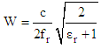 | (2) |
Step 2: Calculation of the effective dielectric constant  The effective dielectric constant is determined by:
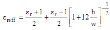 | (3) |
Step 3: Computation of the effective length (Le) of the patch: the effective length of the patch is found from: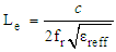 | (4) |
Step 4: Calculation of the patch length extension (): The patch length extension is obtained from (Chon, 2010) as: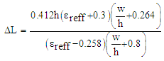 | (5) |
Step 5: Finding the actual (physical) length of the patch (L): The patch length is found from (6) as: | (6) |
Hence, the actual length of the patch is: | (7) |
Step 6: Calculation of the ground plane dimensions (Lg and Wg): The transmission line model is applicable to infinite ground planes only. However, for practical considerations, it is essential to have a finite ground plane. It has been shown by (Balanis, 2005), that similar results for finite and infinite ground plane can be obtained if the size of the ground plane is greater than the patch dimensions by approximately six times the substrate thickness all around the periphery. Hence, for this design, the length of the ground plane (Lg), and width of the ground plane (Wg) were computed with (8 and 9) respectively as: | (8) |
 | (9) |
Step 7: Determination of the inset feed depth  The inset feed depth
  is determined by first calculating the resonant input edge resistance (Rin) of the patch. (Balanis, 2005) states that the resonant input edge resistance (Rin) of an RMSA, taking into account the mutual effects between the radiating slots is given by (10) as:
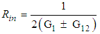 | (10) |
Where  is the self (input edge) conductance of a single slot,
  is the mutual conductance between the two slots, the plus (+) sign is used for modes with odd (anti-symmetric) resonant voltage distribution beneath the patch and between the slots, while the minus (-) sign is used for modes with even (symmetric) resonant voltage distribution.The self-conductance
  of a single slot based on the cavity model is given by (Alsager, 2011; Balanis, 2005; Martin & Sayeed, 2011) as:
 | (11) |
Where  is the radiated power, and
  is the voltage across the slot. The radiated power is stated in Balanis (2005) as:
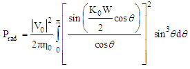 | (12) |
Substituting (12) into (11), the self-conductance  is expressed in (Balanis, 2005) as:
 | (13) |
Where I1 is the integral defined by: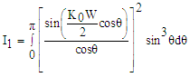 | (14) |
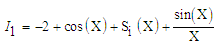 | (15) |
But  | (16) |
where:  = constant
 = free space wave propagation constant
 = width of the patch
 = sine integralSubstituting
  and
and  into (16) gives:
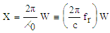 | (17) |
The mutual conductance (G12) between the two radiating slots is defined by (Balanis, 2005; Martin & Sayeed, 2011) as: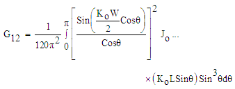 | (18) |
where  is the Bessel function of the first kind of order zero.The position of the recessed feed point
  relative to the leading radiating edge of rectangular patch is obtained based on the formula in (Balanis, 2005) given by (19):
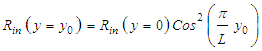 | (19) |
where: = input resistance at recessed feed point from leading radiating edge or input resistance (characteristic impedance) of the microstrip transmission line
  = input resistance at leading radiating edge or input edge resistance of the patch L = length of the patch
  = inset feed depth or inset length from slot at the leading edge of patch.Therefore, the inset feed depth for
  from (19) is:
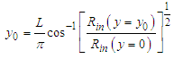 | (20) |
Step 8: Calculation of the inset (feed) gap (g): The feed gap (notch width) in millimetres is computed based on (21) given in (Martin & Sayeed, 2011) as: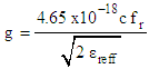 | (21) |
Step 9: Determination of the feed length: The feed length of the microstrip transmission line is determined using (22): | (22) |
Step 10: Evaluation of the width of the microstrip line  The design of the width of a microstrip transmission line feed is computed based on the formulas stated in (Balanis, 2005; Pozar, 2012) as:
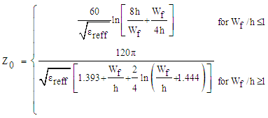 | (23) |
where: Z0 = the characteristic impedance of the microstrip transmission line.For a given characteristics impedance (Z0) and dielectric constant  , the
, the  ratio is determined according to (Pozar, 2012) as:
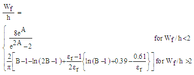 | (24) |
where: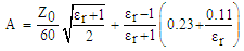 | (25) |
 | (26) |
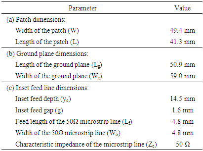
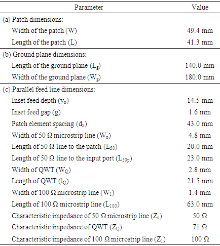
The summary of the results of the design calculations for various dimensions of patch, ground plane and the inset feed line for the single element inset fed RMSA is given in Table 1.Table 1. Dimensions for single element inset fed RMSA
 |
| |
|
The designed single element inset fed RMSA in Ansoft HFSS is shown in Figure 1.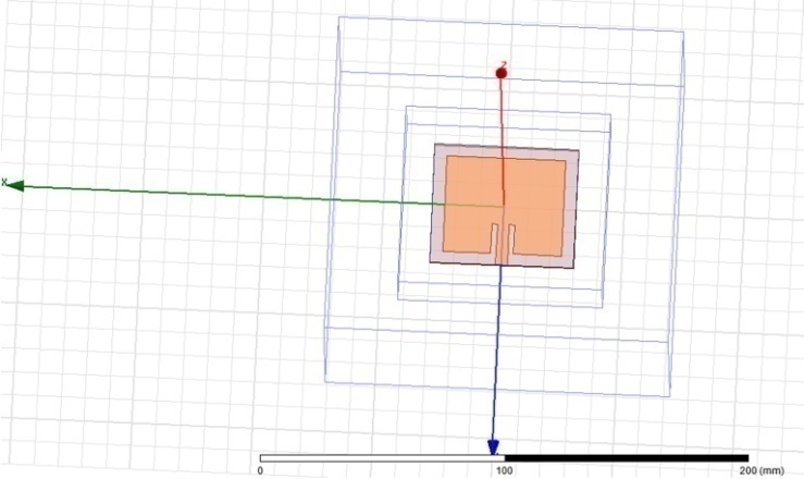 | Figure 1. Single element inset fed rectangular microstrip patch antenna |
3.2. Design of Rectangular Microstrip Antenna Arrays
The single element rectangular microstrip patch antenna cannot satisfy the gain and bandwidth requirements for many wireless communication systems (Godara, 2002). Furthermore, single microstrip patch antennas are not suitable for applications which need high gain, beam scanning and large bandwidth. The performance of the single microstrip patch antenna in terms of low gain is improved in this paper by implementation of single patch antenna in array configurations. In the succeeding sub-sections, the design of 2 and 4 patch elements configured as one dimensional 2x1 and 4x1 parallel feed structures were used in the design of the rectangular microstrip antenna arrays. The microstrip lines are split by using symmetrical T-junction power dividers.
3.2.1. Design of a 2x1 Rectangular Microstrip Antenna Array
The design of a 2x1 (2 elements), single band rectangular microstrip antenna array arrangement for WLAN application is presented in this sub-section. The design specifications for the inset fed 2x1 arrays are: resonant frequency  = 2.4 GHz, dielectric constant
  = 2.2 and height of the dielectric substrate (h) is 1.6 mm. The physical dimensions and the input edge resistance of each single patch element in the 2x1 array configuration are as follows: the width of the patch (W) = 49.4 mm; the effective dielectric constant of the patch
  = 2.11; the actual length of the patch (L) = 41.3 mm; the inset feed depth
  = 14.5 mm; the input edge resistance of the patch
  = 244.79 Ω; and the inset feed gap (g) = 1.6 mm.The 2x1 array is fed by a symmetrical one dimensional parallel feeding arrangement with proper impedance matched network. The characteristic impedance (Z0) of the microstrip line connected to a 50 Ω source (input port) is Z0 = 50 Ω. The 50 Ω microstrip line splits at the T-junction to two microstrip lines. The characteristics impedance of the two microstrip lines is given as:
 | (27) |
where the factor n is the number of microstrip transmission lines emanating from a node connected to a source generator.The characteristics impedance (Z1) of the two microstrip lines is given by (27) as: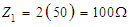 The 50 Ω microstrip line width (W0), and the 100 Ω microstrip line width (W1) are determined using (17).The two 100 Ω microstrip lines are transformed by two quarter–wave transformers (QWTs) to 50 Ω microstrip lines feeding the two antennas. The characteristics impedance of a quarter-wave transformer (ZQ) is given by (Khraisat, 2012) as:
 | (28) |
where:  = characteristics impedance of the 50 Ω line, and
  = characteristics impedance of the 100 Ω line.The summary of the results of the design calculations and specifications for various dimensions of patch, ground plane and parallel feed line network for the 2x1 inset fed RMSA is presented in Table 2.
Table 2. Design dimensions for the 2 x 1 inset fed RMSA
 |
| |
|
The designed 2x1 inset fed RMSA array in Ansoft HFSS is shown in Figure 2.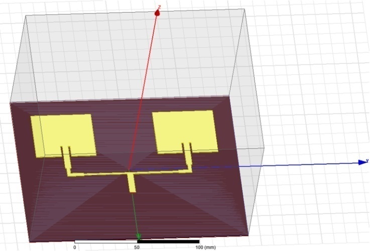 | Figure 2. Designed 2x1 inset fed rectangular microstrip antenna array |
3.2.2. Design of a 4x1 Rectangular Microstrip Antenna Array
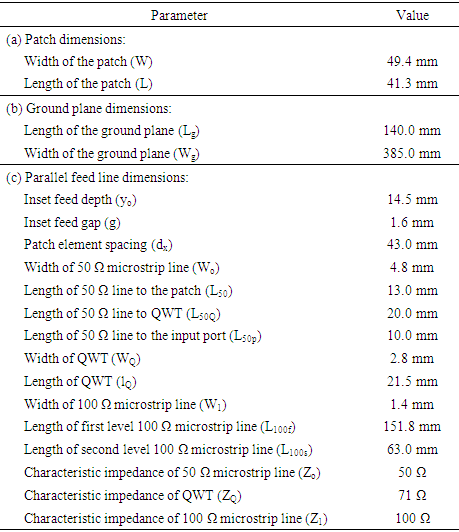
The design of a 4x1 (four-elements), single band rectangular microstrip antenna array is presented in this sub-section. The design specifications for the inset fed 4x1 array are: the same with 2x1 array. The summary of the results of the design calculations and specifications for various dimensions of patch, ground plane and parallel feed line network for the 4x1 inset fed RMSA is given in Table 3.Table 3. Design dimensions for the 4x1 inset fed RMSA
 |
| |
|
The designed 4x1 inset fed RMSA array in Ansoft HFSS is shown in Figure 3.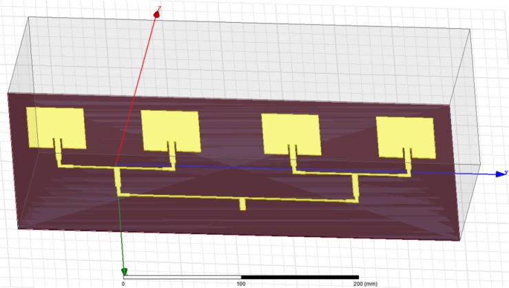 | Figure 3. Designed 4x1 inset fed rectangular microstrip antenna array |
4. Results and Discussion
The simulation results using Ansoft HFSS are as shown in Figure 4 to Figure 12.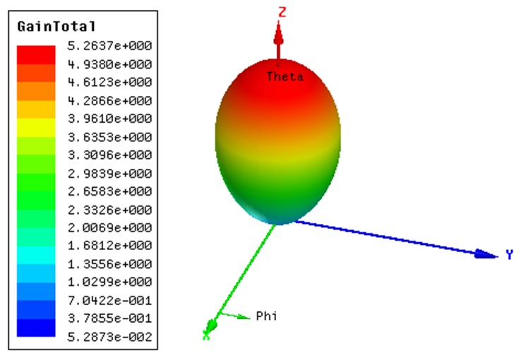 | Figure 4. 3D gain of single element rectangular microstrip antenna |
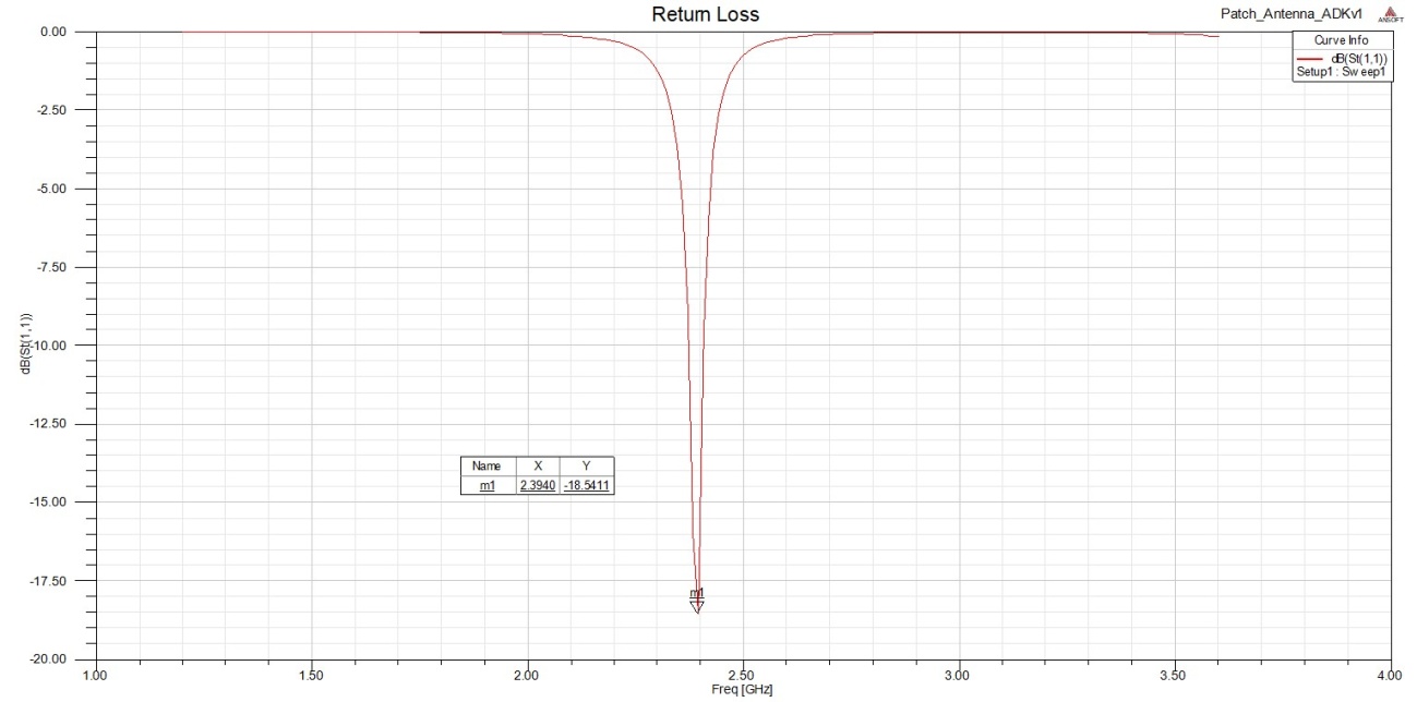 | Figure 5. Return loss versus frequency of single element rectangular microstrip antenna |
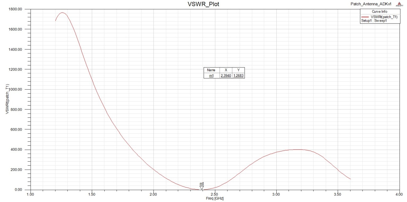 | Figure 6. VSWR versus frequency for the single element rectangular microstrip antenna |
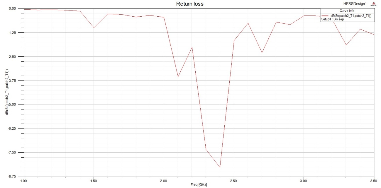
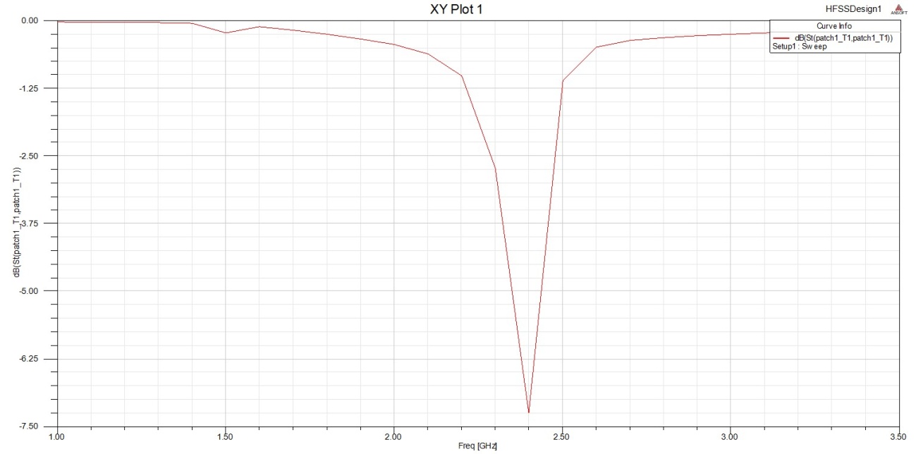 | Figure 7. Return loss of 2x1 rectangular microstrip antenna array |
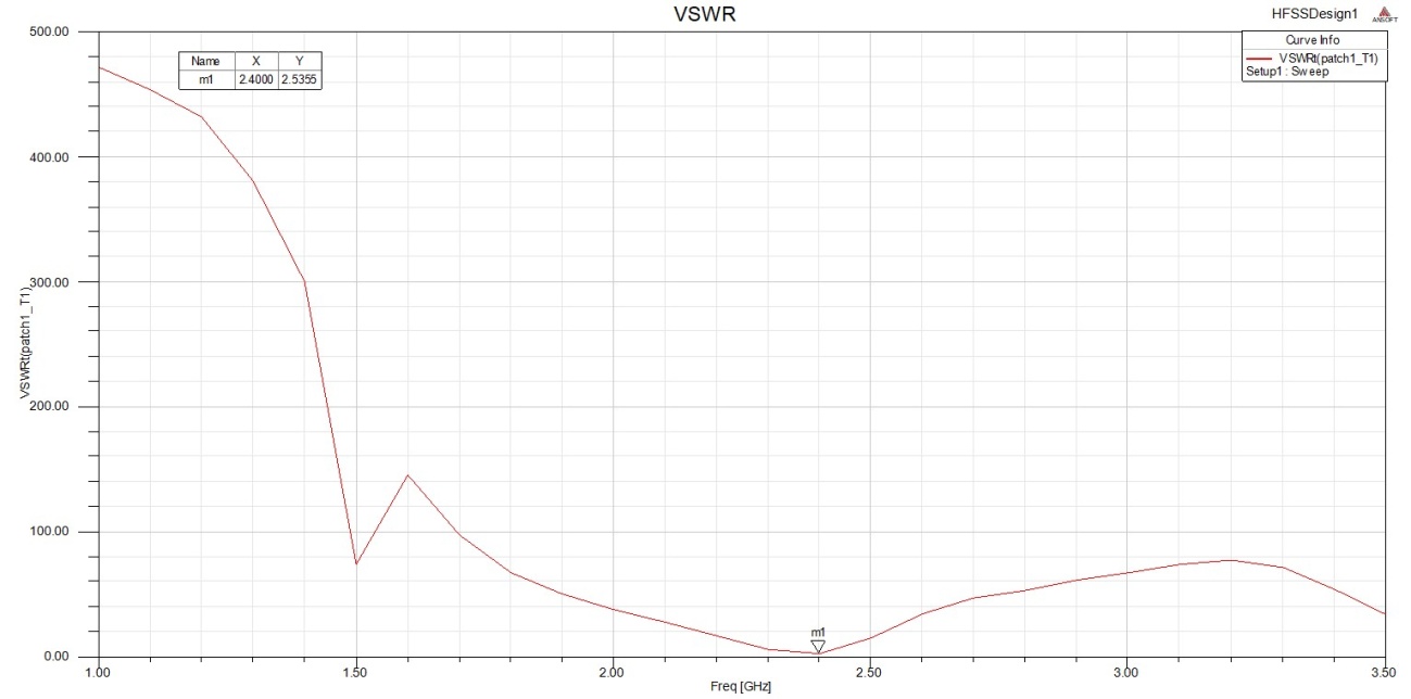 | Figure 8. VSWR versus frequency for the 2x1 antenna array |
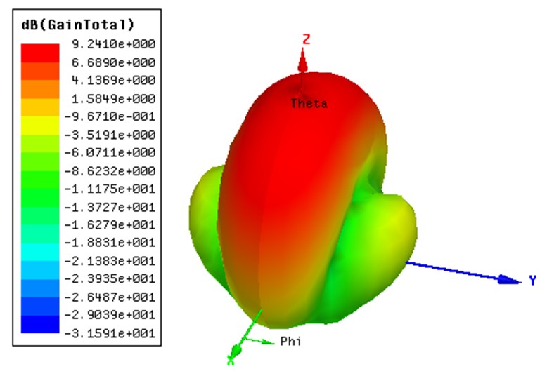 | Figure 9. 3D gain of 2x1 rectangular microstrip antenna array |
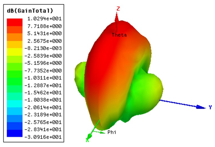 | Figure 10. 3D gain of 4x1 rectangular microstrip antenna array |
 | Figure 11. Return loss of 4x1 rectangular microstrip antenna array |
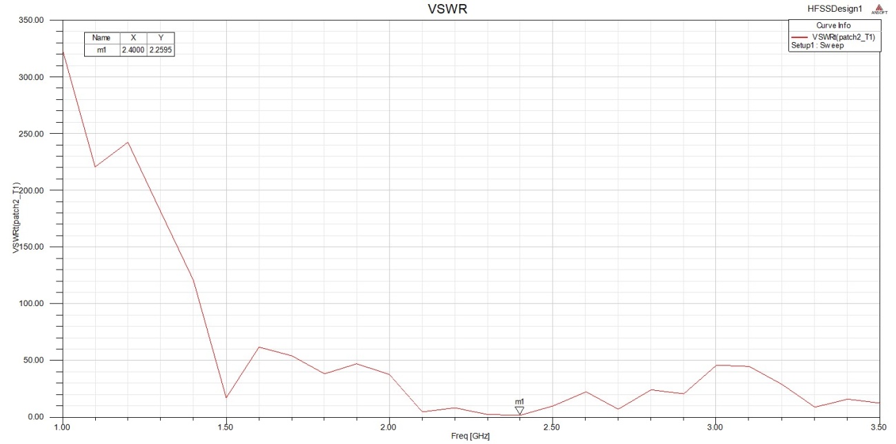 | Figure 12. VSWR versus frequency for the 4x1 antenna array |
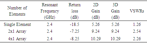
The summary of the simulation results showing the comparisons of (the antenna characteristics) resonant frequency, return loss values, 2D and 3D gain as well as VSWRs for single element RMSA, 2x1 and 4x1 RMSA arrays respectively is shown in Table 4.Table 4. Summary of simulation results
 |
| |
|
Based on Table 4, the proposed designed single element RMSA and the 2x1 and 4x1 RMSA arrays resonated at the designed operating frequency of 2.4 GHz. This indicates that the designed antennas are functioning properly since they all resonated at the desired centre frequency of 2.4 GHz.The return loss of -18.54 dB for the single element antenna is a good value since it is below (less than) the minimum specified -9.5 dB for good MSA designs. Also, the return loss of -18.54 dB signifies that minimum power is reflected from the antenna to the source input port. The return losses of -7.25 dB and -8.25 dB respectively by the 2x1 and 4x1 RMSA arrays also provide good return loss values since they lie at the negative deep at the operating values of 2.4 GHz, and the values are close to the standard -9.5 dB values for good designs.
5. Conclusions
In this paper, the mathematical calculations and methods for the designs of an innovative single element, 2x1 and 4x1 inset fed rectangular microstrip antennas resonating at 2.4 GHz is presented. The simulation of the designed antennas was performed in Ansoft HFSS V. 15.0. The antennas performance characteristics such as return loss, gain and VSWR were obtained in the simulation. The simulation results of the single element rectangular microstrip antenna produced a return loss of -18.54 dB at 2.4 GHz, gain of 5.26 dB and a VSWR of 1.26. The simulation results of the 2x1 rectangular microstrip antenna array showed a return loss of -7.25 dB at 2.4 GHz, gain of 9.24 dB, VSWR of 2.54, and that of 4x1 rectangular microstrip antenna array produced a return loss of -8.25 dB at 2.4 GHz, gain of 10.29 dB and VSWR of 2.26 respectively. The simulation results show that the gain of single element RMSA is improved using the novel designed 2x1 and 4x1 rectangular microstrip antenna arrays. Good results for return loss, resonant frequency, gain and VSWRs for single element and array antennas have been achieved. The problem of low gain by single element RMSA has been addressed by the new RMSA array designs presented in this research work. The novel designed antennas can be used for wireless local area networks, S band communications and modern wireless communication systems applications.
References
| [1] | Alsager, A. F. (2011). Design and Analysis of Microstrip Patch Antenna Arrays, Unpublished Masters Thesis, University College of Boras,. Boras, Sweden. |
| [2] | Balanis, C. A. (2005). Antenna Theory: Anaysis and Design. 3rd ed. New Jersey: John Wiley and Sons, Inc. pp. 1 - 144, 811 - 876. |
| [3] | Buttar, T. S., & Sharma, N. (2014). Design of Rectangular Microstrip Antenna for Wireless Communication. International Journal of Modern Sciences and Engineering Technology (IJMSET), 1(6), 47 - 52. |
| [4] | Chon, N. L. (2010). Photonic Antenna for Wireless Local Area Network backhaul Application, Unpublished Masters Thesis, Universiti Teknologi,. Malaysia, Malaysia. |
| [5] | Gary, R., Bhartia, P., Bahl, I. & Ittipboon, A. (2001). Microstrip Antenna Design Handbook. Boston: Artech House Inc., pp. 1 - 812. |
| [6] | Godara, L. C. (2002). Handbook of Antennas in Wireless Communications. Boca Raton: CRC Press, 6-1 - 6-27. |
| [7] | Khraisat, Y. S. (2012). Design of 4 Elements Rectangular Microstrip Patch Antenna with High Gain for 2.4GHz Applications. Modern Applied Science, 6(1): 68 - 74. |
| [8] | Kumar, G., & Ray, K. P. (2003). Broadband Microstrip Antennas. Boston: Artech House Inc. |
| [9] | Martin, M. A., & Sayeed, A. I. (2011). A Design Rule for Inset-fed Rectangular Microstrip Patch Antenna. WSEAS Transaction on Communication, 1(9), 63 - 72. |
| [10] | Milligan, T. A. (2005). Modern Antenna Design. 2ed. New Jersey: John Wiley and Sons Inc. |
| [11] | Pozar, D. M. (2012). Microwave Engineering. 4th ed. John wiley and Sons. |
| [12] | Rawat, D. S., Singh, G., & Singh, R. P. (2014). Design of Corporate fed 1x2 Microstrip Array Antenna for X band Applications. International Journal of Computer Applications, 95(6), 17 - 19. |
| [13] | Roy, A. A., Mom, J. M., & Igwue, G. A. (2013). Enhancing the Bandwidth of a Microstrip Patch Antenna using slots shaped Patch. American Journal of Engineering Research (AJER), 29, 23 - 30. |
| [14] | Sainati, R. A. (1996). CAD of Microstrip Antennas for Wireless Applications. Norwood: Artech House. |

 Abstract
 Reference
 Full-Text PDF
 Full-text HTML