Duaa Alyas Karim Aljaf1, Raad Sami Fyath2
1Department of Electronic and Communications Engineering, Al-Nahrain University, Baghdad, Iraq
2Department of Computer Engineering, Al-Nahrain University, Baghdad, Iraq
Correspondence to: Duaa Alyas Karim Aljaf, Department of Electronic and Communications Engineering, Al-Nahrain University, Baghdad, Iraq.
| Email: |  |
Copyright © 2019 The Author(s). Published by Scientific & Academic Publishing.
This work is licensed under the Creative Commons Attribution International License (CC BY).
http://creativecommons.org/licenses/by/4.0/

Abstract
This paper presents guidelines to design a configurable beam-steering network for phase array antennas (PAAs) using the photonic true time delay line (TTDL) proposed in the accompanying paper [1]. Experimental and simulation results are given to support the concepts of the design. Six single-element patch and stripline antennas are designed for 2.4, 5.8, and 10 GHz operations and their radiation patterns are simulated. Five of these antennas, which operate at 2.4 and 5.8GHz, are fabricated and experimentally tested and their measured radiation pattern performance are found to be closed to the simulation. Then six PAAs incorporating these radiating elements are designed and their scanning capabilities based on the proposed configurable steering network are investigated for different number of radiating elements N (4, 8, and 16). The radiation pattern parameters of the designed PAAs are evaluated as a function of the steering angle. The obtained results confirm the scanning capability of the proposed beam-steering network. The simulation results reported in this work are based on three software packages, namely OptiGrating ver.14-1, OptiSystem ver.14-1, and CST ver. 15.1.
Keywords:
Phase array antenna, Photonics true time delay line
Cite this paper: Duaa Alyas Karim Aljaf, Raad Sami Fyath, Configurable Beam-Steering Network for Phase Array Antennas- Part II: Design Guidelines and Results, International Journal of Networks and Communications, Vol. 9 No. 2, 2019, pp. 53-72. doi: 10.5923/j.ijnc.20190902.01.
1. Introduction
The microwave photonics (MWP) addresses the use of photonic devices and optical techniques to process microwave (MW) signals [2, 3]. Recently, there have been intense research activities to generate, transport, manipulate, and measure high- speed microwave signals using MWP technique [4, 5]. This technique makes use of the wide processing bandwidth obtained from up converting MW frequencies to optical frequencies and the availability of low- loss optical fibers as a transmission medium. In addition to that, some of the devices used in MWP technique can be implemented using silicon photonic platform [6, 7]. This platform enables efficient and low-cost integration of hybrid photonic, optical, and electronic devices. One of the main applications of MWP is to design compact, high-bandwidth beam-steering and -forming networks for phase array antennas [8, 9]. These networks usually use photonic true time delay lines (TTDLs). This paper makes use of the reconfigurable photonic TTDL described in our previous paper [1] to design and simulate beam-steering networks using the proposed delay line reported in [1]. The motivation behind this study is to address the capability of the proposed configurable beam- steering network on dealing with PAAs operating at different frequencies (2.4, 5.8, and 10 GHz) and different radiating elements (4, 8, and 16). These goals are achieved using the following steps(i) Guidelines are presented to design the configurable photonics TTDL based on required operating frequency and number of radiating elements. The line uses cascaded fiber Bragg gratings (FBGs) interconnected by optical switches (OSs). A 80 mm length linearly chirped FBG (LCFBG) with modified Gaussian apodization is used on the design. Parametric study has been performed for this FBG and the results are reported in [1]. (ii) The proposed configurable steering network is implemented in Optisystem environment. This commercial software has been issued by Optiwave company to support the simulation of optical communication systems. In this work, the system simulated by this software contains array of semiconductor laser diodes, optical wavelength multiplexer and demultiplexer, optical modulator, optical switches, and array of direct-detection optical receivers. The system also contains many LCFBGs and makes use of another software from Optiwave, namely OptiGrating, to characterize the performance of the used FBGs at the initial state of simulation. (iii) Different single-element antennas are designed, fabricated, and their performance are measured and compared with simulated ones.(iv) The results obtained in part (iii) are used as a guideline to design PAAs incorporated the investigated single-radiating elements. Further, the steering capability of the designed PAAs are examined using the proposed configurable beam-steering network under different operating frequencies and number of radiating elements.The rest of the paper is organized as follows. Section 2 presents the characteristic parameters of the designed configurable TTDL. Simulated and experimental results describing the performance of the designed single-element antennas are given in Sections 3. Section 4 presents simulation results related to the performance of the designed PAAs. The main conclusions drawn from this study are listed in Section 5. Additional results describing the radiation patterns of the designed PAAs are given in the Appendix.
2. Characteristic Parameters of the Designed Configurable Photonic TTDL
Table 1 lists the dependence of the maximum allowable number of radiating elements, to be contained by a PAA whose steering angle can be scanned over  range, on number of used FBG,
  . The results are presented for three microwave frequencies
  and 10 GHz, and calculated using
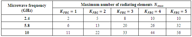
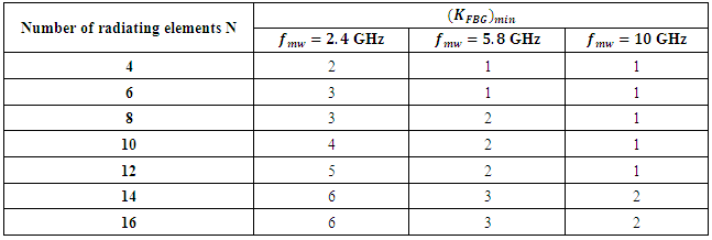
 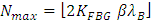 . Note that at 2.4 GHz, the 4 and 8-PAAs need 2 and 3 FBGs, respectively. Going to 5.8 GHz, 4, 8, and 16-PAAs need 1, 2, and 3 FBGs, respectively. At 10GHz, a single FBG can be used to for scanning 4- and 8-PAAs while two FBGs are needed for scanning 16-PAAs. These results can be also deduced from Table 2 which shows the minimum number of FBGs needed to design a steering network for an N-phase array antenna with
  scanning capability.
Table 1. Maximum allowable number of radiating elements, to be contained by an antenna whose steering angle can be scanned over 90° range, as a function of number of used FBG, KFBG
 |
| |
|
Table 2. Minimum number of FBGs needed to design a steering network for an N-phase array antenna with 90° scanning capability
 |
| |
|
Recall that the time delay introduced by cascading reflection-mode FBGs equals to the accumulation of the individual time delays. For each FBG, the time delay difference between successive semiconductor lasers depends on wavelength spacing  . Therefore, using
  identical devices in the photonic line offers an effective time delay difference
  Since identical FBGs have the same dispersion parameters
  , then
  can be considered as the virtual or effective wavelength spacing
  . To generalize this concept for cascading nonidentical FBGs, the effective wavelength spacing is defined as
  | (1) |
where  is the average dispersion of the used FBGs.Figure 1 shows the variation of the steering angle with the effective wavelength spacing
  . The results are presented for identical cascaded FBGs and for three microwave frequencies (2.4, 5.8, and 10 GHz). The calculations are based on equ. (2) [10] and they are independent of number of antenna radiating elements.
 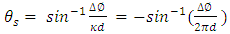 | (2) |
These results will be used as references when the steering angles are deduced using CST software for PAAs designed with different number of radiating elements.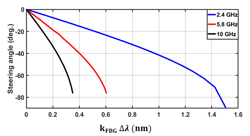 | Figure 1. Variation of steering angle with the effective wavelength spacing 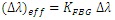 . The results are presented for identical cascaded FBGs . The results are presented for identical cascaded FBGs |
3. Performance of the Designed Single-Radiating Element Antennas
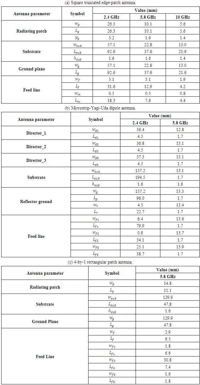
Five antennas are designed and fabricated for 2.4 and 5.8 GHz operation. An additional antenna is designed for 10 GHz operation and is not fabricated due to the lack of test equipment at this wavelength in our department laboratories. The six antennas are designed with single-radiating element on dielectric material having 4.3 relative permittivity (FR-4). The performance of these antennas will be used as a guideline to discuss the results related to PAA counterparts in the next section. The designed antennas are Antenna 1: 2.4 GHz Square truncated edge-patch antenna.Antenna 2: 2.4 GHz Microstrip-Yagi-Uda dipole antenna.Antenna 3: 5.8 GHz Square truncated edge-patch antenna.Antenna 4: 5.8 GHz Microstrip-Yagi-Uda dipole antenna.Antenna 5: 5.8 GHz 4-by-1rectangular patch antenna.Antenna 6: 10 GHz Square truncated edge-patch antenna.The configurations of square truncated edge-patch, microstrip-Yagi-Uda dipole, and 4-by-1 rectangular patch antennas are illustrated in Figures 2 (a-c), respectively. Table 3 lists the main geometric parameters values of the designed six single-radiating element antennas.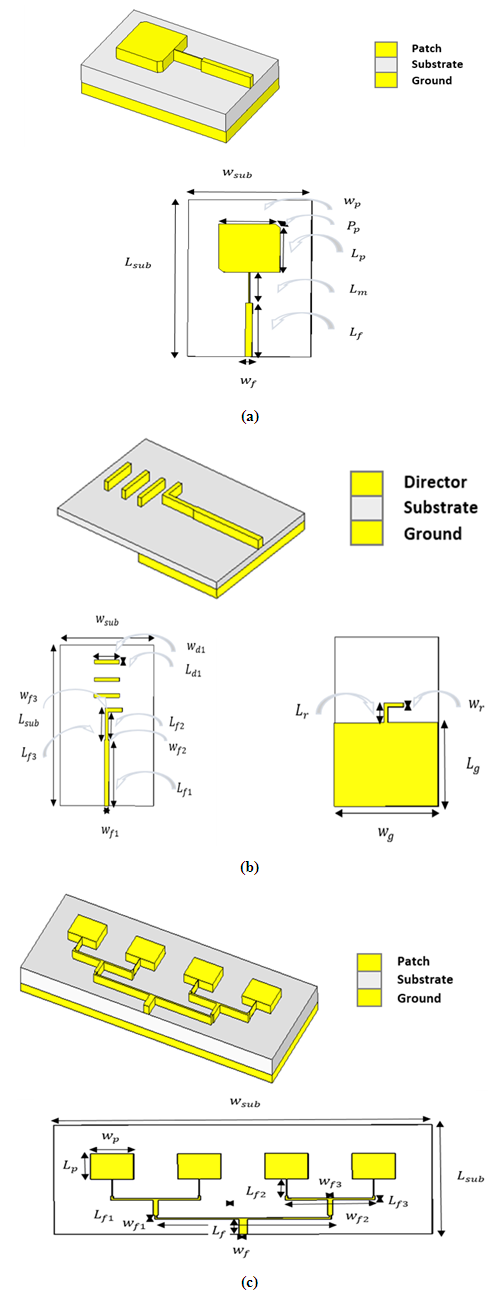 | Figure 2. Configurations of (a) square truncated edge-patch antenna, (b) microstrip-Yagi-Uda dipole antenna, and (c) 4-by-1 rectangular patch antenna |
Table 3. Main geometric parameters values of the six designed single-radiating element antennas
 |
| |
|
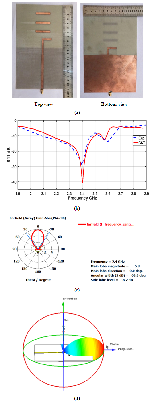
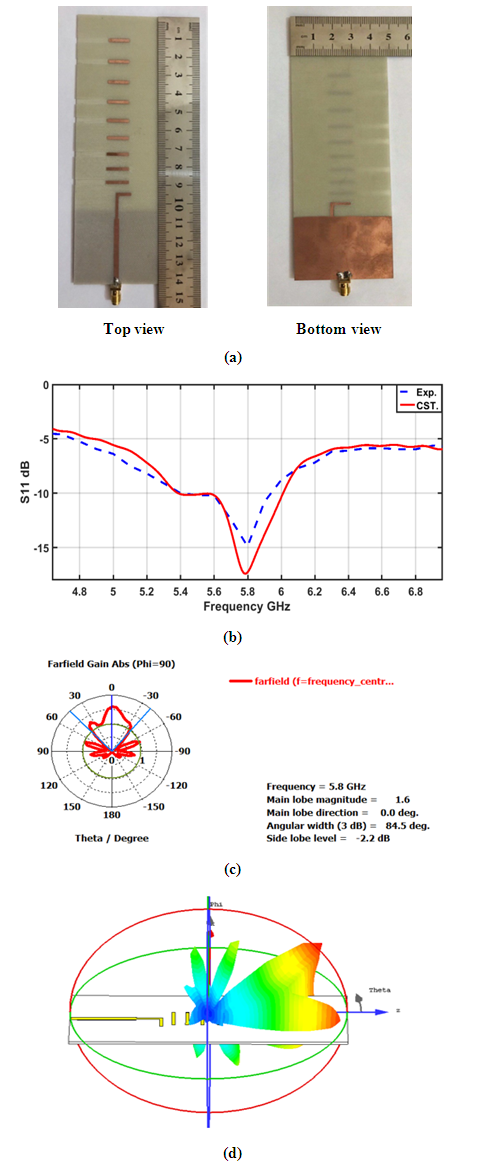
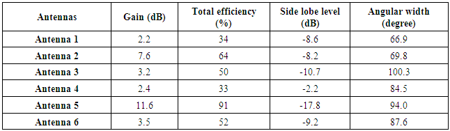
Figures 3-7 present results related to the 2.4 and 5.8 GHz antennas. Each figure contains four parts. Part a shows the antenna experimental version. Part b of the figure compares the simulated and measured  spectra. The simulation results are obtained using CST software. Note that the experimental data are in good agreement with the simulation results. Parts c and d show the simulated polar and 3D radiation patterns of the antenna, respectively. The results related to the 10 GHz antenna are given in Figure 8 where only simulation performance predictions are included. Performance comparison among the six antennas are given in Table 4 and are based on CST simulation.
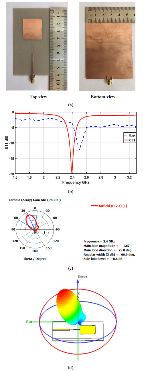 | Figure 3. 2.4 GHz Square truncated edge-fed antenna. (a) Experimental version (b) Simulated and measured S11 spectra (c) Polar radiation pattern (d) 3D radiation pattern |
 | Figure 4. 2.4 GHz Printed Microstrip-fed Yagi-Uda Dipole Array antenna. (a) Experimental version (b) Simulated and measured S11 spectra (c) Polar radiation pattern (d) 3D radiation pattern |
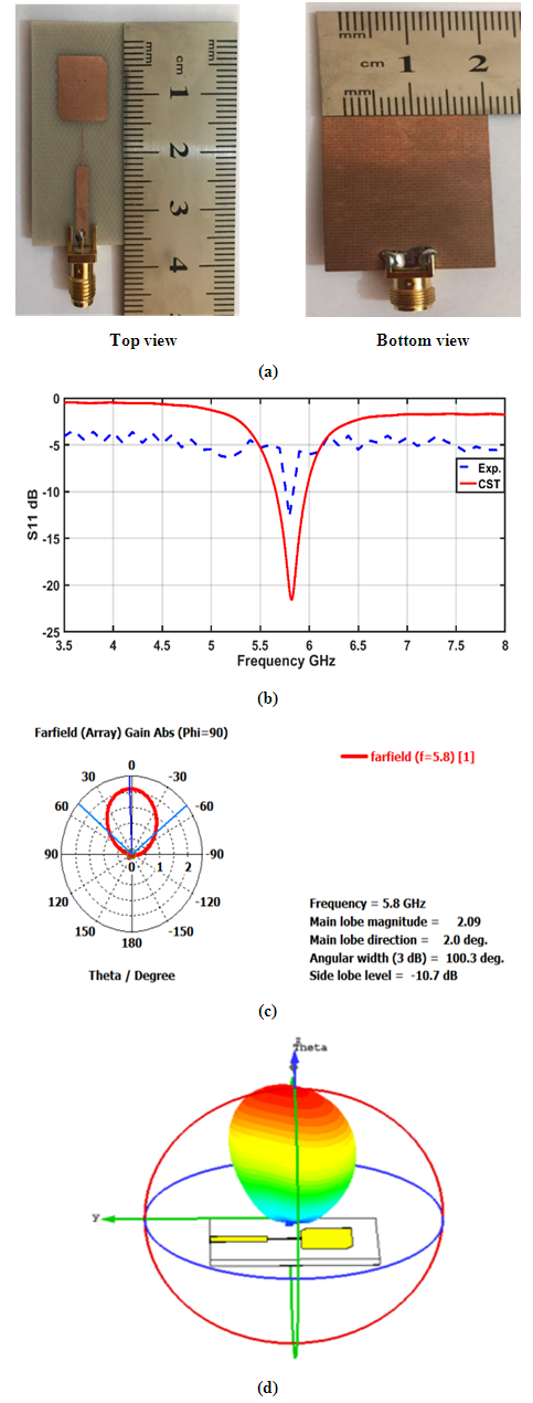 | Figure 5. 5.8 GHz Square truncated edge-fed antenna. (a) Experimental version (b) Simulated and measured S11 spectra (c) Polar radiation pattern (d) 3D radiation pattern |
 | Figure 6. 5.8 GHz Printed microstrip-fed Yagi-Uda Dipole Array antenna. (a) Experimental version (b) Simulated and measured S11 spectra (c) Polar radiation pattern (d) 3D radiation pattern |
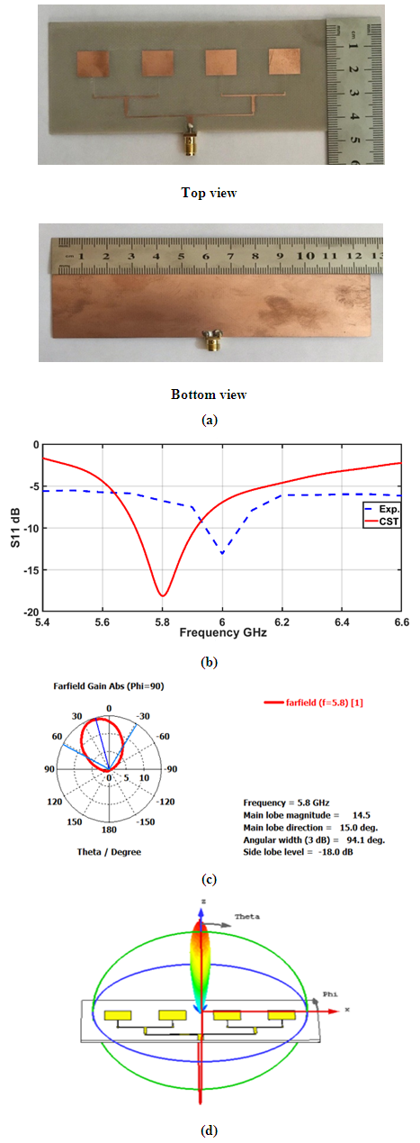 | Figure 7. 5.8 GHz Inset-fed 4-by-1 rectangular patch array with corporate feed antenna. (a) Experimental version (b) Simulated and measured S11 spectra (c) Polar radiation pattern (d) 3D radiation pattern |
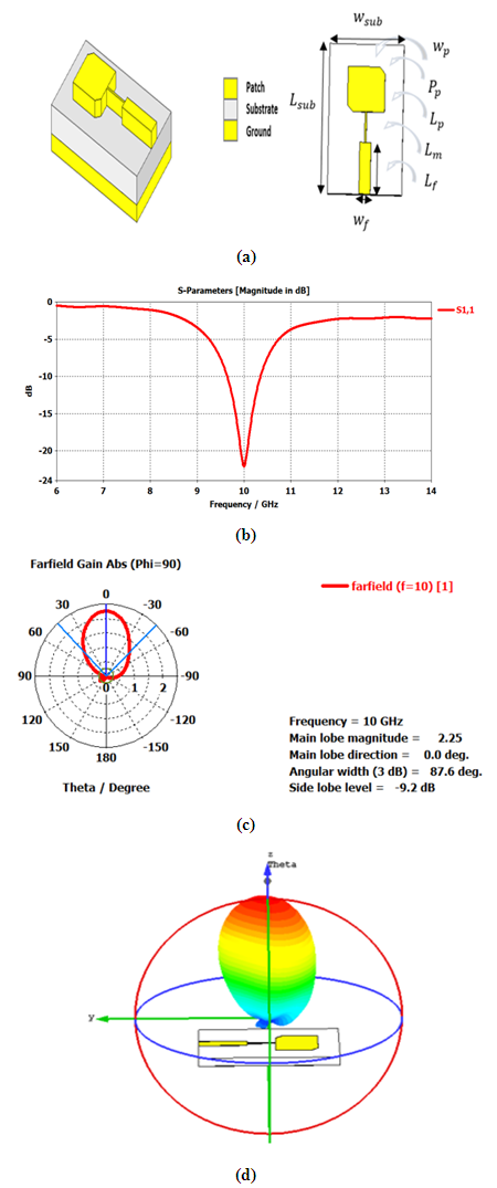 | Figure 8. 10 GHz Square truncated edge-fed antenna. (a) Antenna configuration. (b) Simulated S11 spectra. (c) Polar radiation pattern (d) 3D radiation pattern |
Table 4. Performance comparison among the six designed single-element antennas
 |
| |
|
4. Performance Simulation of the Designed PAAs
This section presents simulation results for six PAAs, each uses one of the radiating elements described in the previous section as the basic radiator. These PAAs are denoted here by PAAi (i = 1, 2, .., 6) which corresponds to the case when the ith single-element antenna described in the previous section is used in the design. The results are reported for different number of radiating elements N, used to design the PAA, and the effective wavelength spacing  The simulation results are based on "OptiSystem ver. 14-1" and "CST ver. 15.1" softwares and performed through two successive steps(i) The photonic TTDL-based beam-steering network is simulated in the OptiSystem environment (see Figure 9). This software are usually used to simulate optical communication systems and used here to predict the time delay associated with the microwave signal embedded on the propagated optical carrier as a function of
  This software may be coupled with OptiGrating software if extra modeling is required for the used LCFBG. Both OptiSystem and OptiGrating software are issued by the same company under the title of Optiwave [11].(ii) The time delay results obtained in step ‘i’ are fed to the PAA designed in the CST environment to control its steering angle. The CST also gives radiation performance simulation results related to the PAA operating with each of the steering angles.
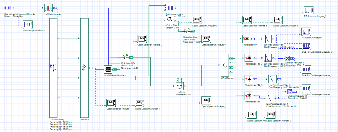 | Figure 9. Designed photonic TTDL-based beam-steering network in the OptiSystem environment |
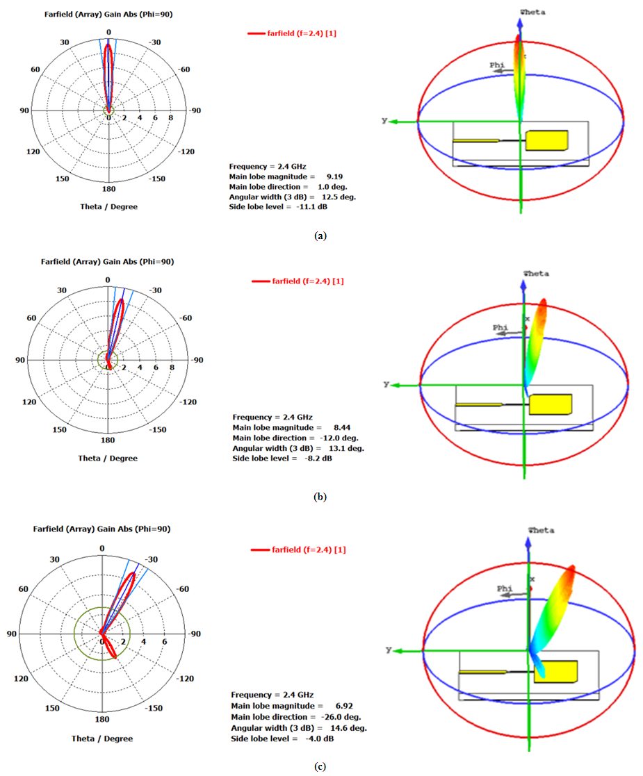
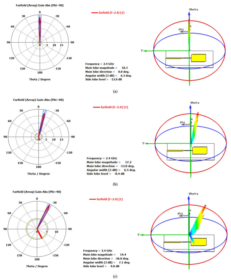
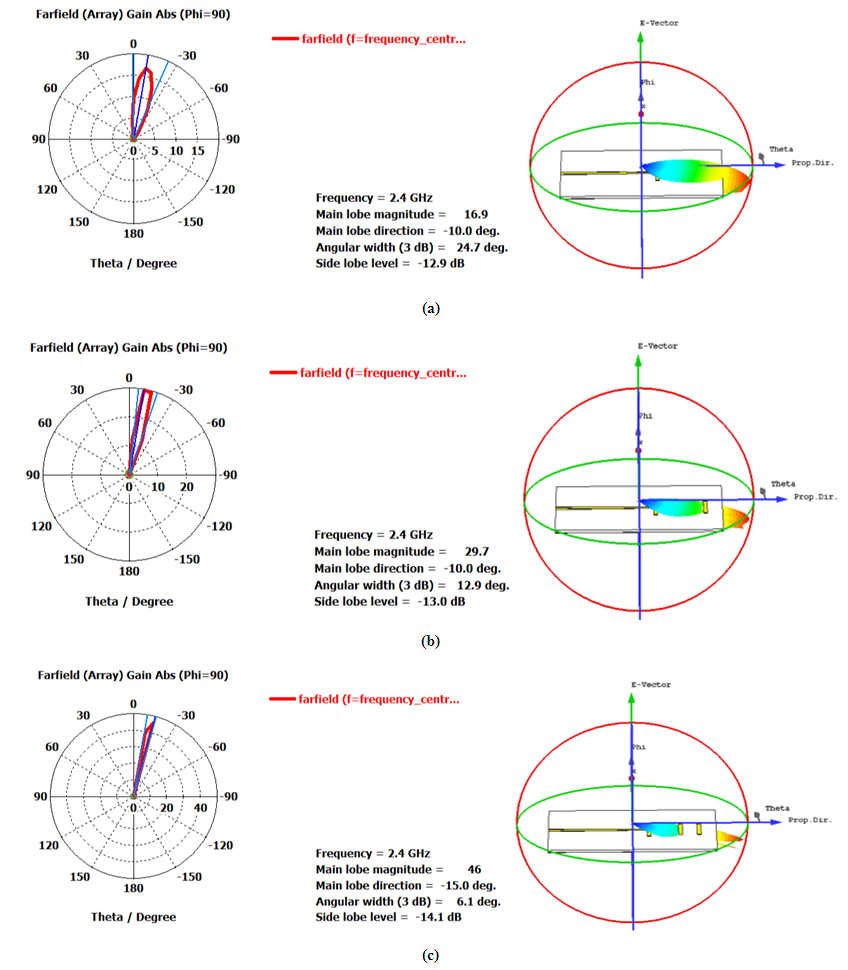
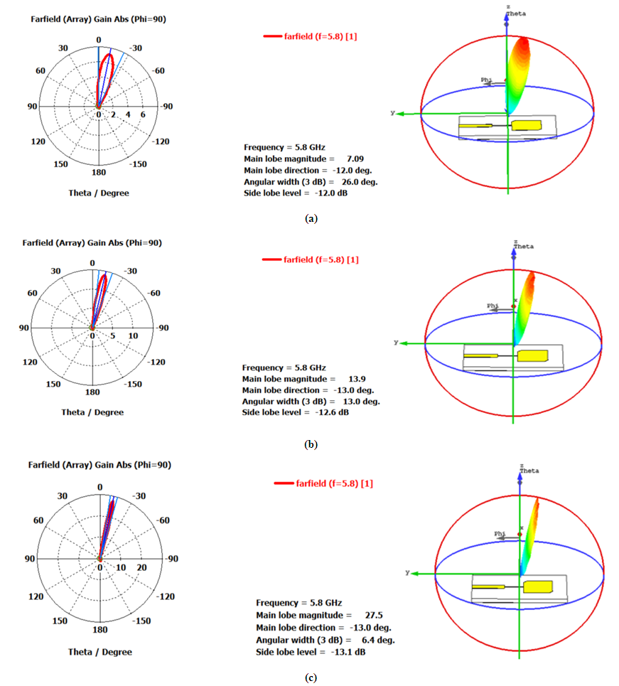
The radiation performance of PAA1, which is designed with 2.4GHz radiating elements, are simulated for three values of N (N = 4, 8, and 16) and the results are depicted in Figures 10-14. Figures 10 (a-c) show the polar and 3D radiation patterns corresponding to  steering angle
  and for N = 4, 8, and 16, respectively. The variation of radiation pattern with
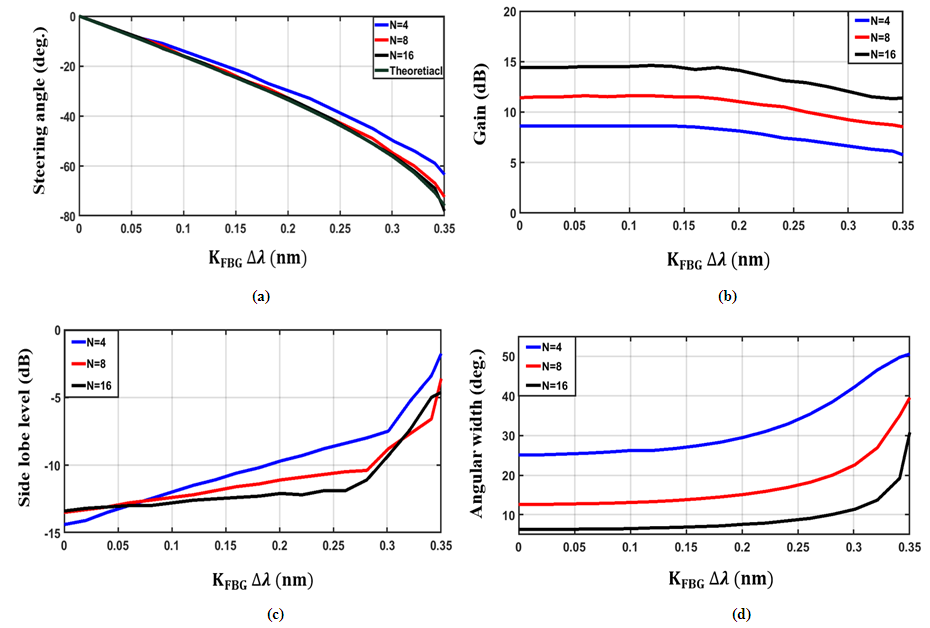
  is given in Figures 11, 12, and 13 for N=4, 8, and 16, respectively. The variations of steering angle, antenna gain, side lobe level, and angular beam width
  with the effective wavelength spacing
  are illustrated for different values of N in Figures 14 (a-d). Investigating the results in Figure 14 reveals the following findings.(i) When N = 8 and 16, the simulated
  characteristics matches the theoretical prediction. (ii) Increasing N from 4 to 8 will increase the gain by approximately 1.4dB over the values of
  considered here. This value should be compared with 1.3dB when N increases from 8 to 16.
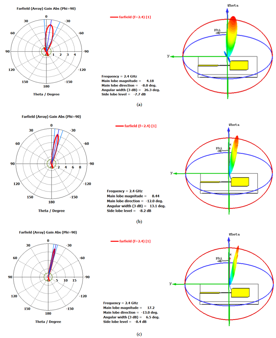 | Figure 10. Radiation patterns at  for PAA1 designed with 2.4 GHz square truncated edge-fed antenna radiating element. (a) N = 4, (b) N = 8, and (c) N = 16 for PAA1 designed with 2.4 GHz square truncated edge-fed antenna radiating element. (a) N = 4, (b) N = 8, and (c) N = 16 |
 | Figure 11. Radiation patterns of PAA1 designed with four radiating elements.  |
 | Figure 12. Radiation patterns of PAA1 designed with eight radiating elements.  |
 | Figure 13. Radiation patterns of PAA1 designed with sixteen radiating elements.  |
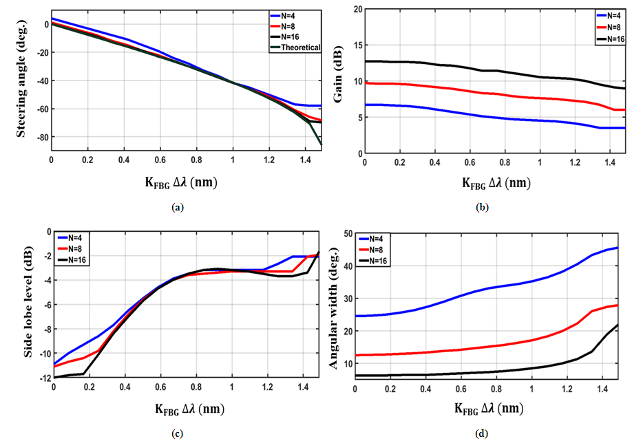 | Figure 14. Radiation performance parameters of PAA1. (a) Steering angle. (b) Gain. (c) Side lobe level. (d) Angular beam width |
(iii) Both side lobe level and angular beam width  increase with increasing
  . The angular beam width is a decreasing function of N. When
  and 6.3 degree for N = 4, 8, and 16. These values are to be compared with 28.9, 13.8, and 6.7 degree for
  nm and 35.2, 17.1, 8.5 degree for
  nm, respectively.The radiation performance of the other five PAAs are also simulated and their radiation profiles are given in the Appendix. Here only the dependence of their radiation performance parameters (steering angle, gain, side lobe level, and angular beam width) on
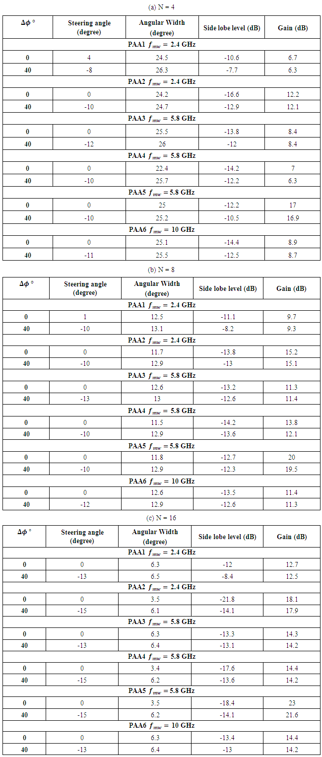
  and N are given. The results are reported in Figures 15-19 for PAA2- PAA6, respectively.Tables 5 (a-c) summarize the radiation performance parameters of the six PAAs at
  and
and  for N= 4, 8, and 16, respectively. Investigating the results in these tables highlights the following findings (i) The gains of the antennas are almost independent of the steering angle when N is fixed.(ii) PAA5 offers the highest gain among the antennas.(iii) All the PAAs have angular beam width less than 6.5° when designed with N=16.
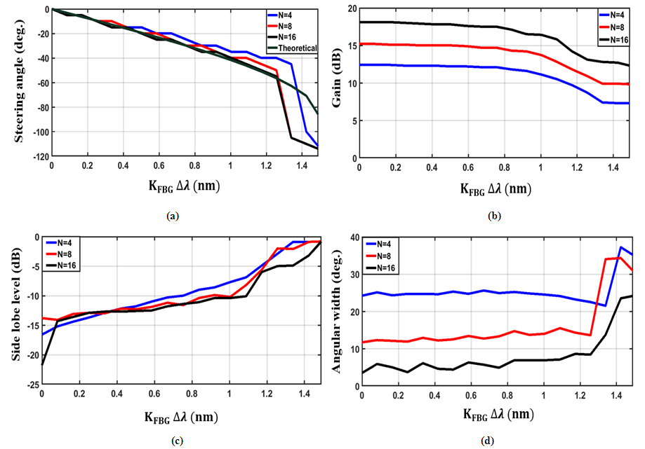 | Figure 15. Radiation performance parameters of PAA2. (a) Steering angle. (b) Gain. (c) Side lobe level. (d) Angular beam width |
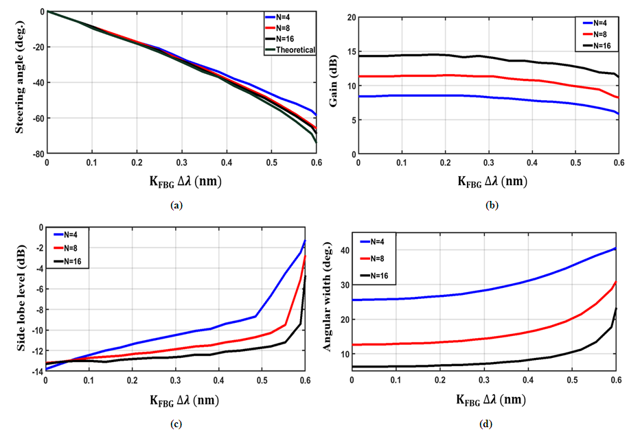 | Figure 16. Radiation performance parameters of PAA3. (a) Steering angle. (b) Gain. (c) Side lobe level. (d) Angular beam width |
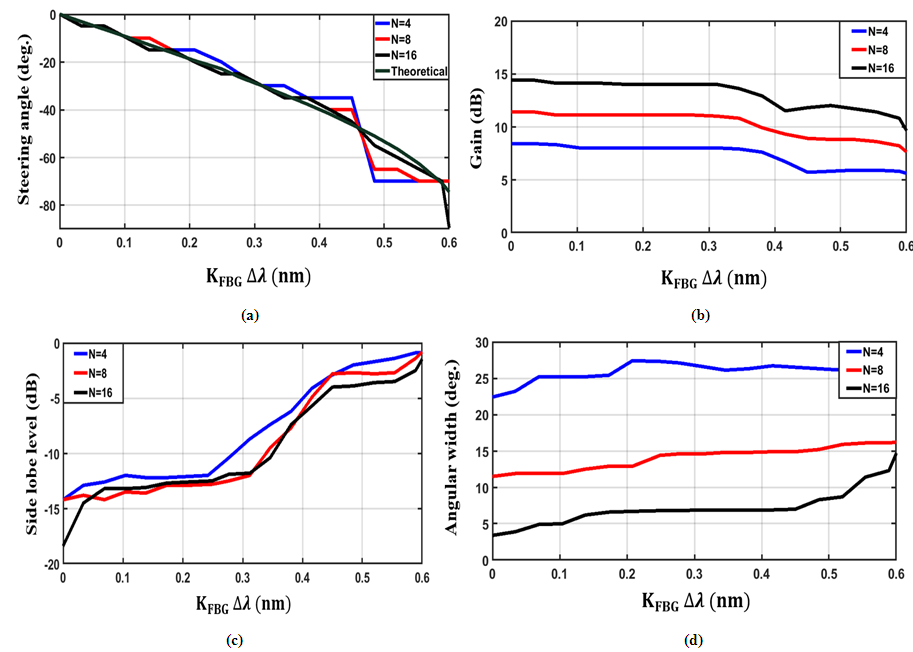 | Figure 17. Radiation performance parameters of PAA4. (a) Steering angle. (b) Gain. (c) Side lobe level. (d) Angular beam width |
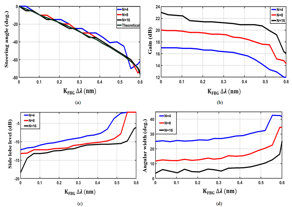 | Figure 18. Radiation performance parameters of PAA5. (a) Steering angle. (b) Gain. (c) Side lobe level. (d) Angular beam width |
 | Figure 19. Radiation performance parameters of PAA6. (a) Steering angle. (b) Gain. (a) Side lobe level. (d) Angular beam width |
Table 5. Radiation performance parameters of the designed six PAAs at
 and 40° steering angles. The values of and 40° steering angles. The values of
 used to obtain 40° steering angle are 335.23, 138.71, 80.45 pm when fmw = 2.4, 5.8, and 10 GHz, respectively used to obtain 40° steering angle are 335.23, 138.71, 80.45 pm when fmw = 2.4, 5.8, and 10 GHz, respectively
 |
| |
|
5. Conclusions
Six PAAs have been designed based on simulation and experimental results related to single-radiating elements operating at 2.4, 5.8 and 10GHz frequency. The scanning capability of these antennas has been investigated when the beam-steering network is designed with the proposed configurable TTDL. The results reveal that(i) The steering network uses 2, 1, and 1 of the designed LCFBGs for 4-element PAA operating at 2.4, 5.8, 10 GHz, respectively. These values are to be compared, respectively, with (3, 2, and 1 for 8-PAAs) and (6,3, and 2 for 16-PAAs). (ii) As the number of radiating elements used in the PAA increases, the simulation results of the steering angle approach the theoretical predictions. (iii) The gains of the six designed PAAs are almost independent of the steering angle when number of radiating elements is kept constant. (iv) PAA5 based on 4-by-1 rectangular patch radiating element offers the highest gain among the six investigated PAAs. (v) When N = 8 and 16, the simulated  characteristics matches the theoretical predictions. (vi) Increasing N from 4 to 8 will increase the gain by approximately 1.4dB over the values of
  considered here. This value should be compared with 1.3dB when N increases from 8 to 16.(vii) Both side lobe level and angular beam width
  increase with increasing
  . The angular beam width is a decreasing function of N. When
 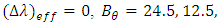 and 6.3 degree for N = 4, 8, and 16. These values are to be compared with 28.9, 13.8, and 6.7 degree for
  = 0.5 nm and 35.2, 17.1, 8.5 degree for
  nm, respectively.The work will be extended in the future to address the possibility of using the proposed photonic TTDL for beam steering of planar PAAs and massive multi-input multi-output antennas used in 5G mobile communications.
Appendix : Radiation Patterns of PAA2-PAA6
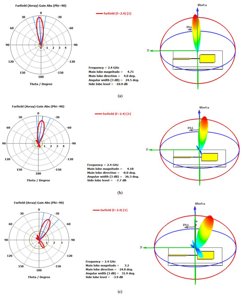
 | Figure A1. Radiation patterns at  for PAA2 (designed with 2.4 GHz microstrip-Yagi-Uda dipole antenna). (a) N = 4, (b) N = 8, and (c) N = 16 for PAA2 (designed with 2.4 GHz microstrip-Yagi-Uda dipole antenna). (a) N = 4, (b) N = 8, and (c) N = 16 |
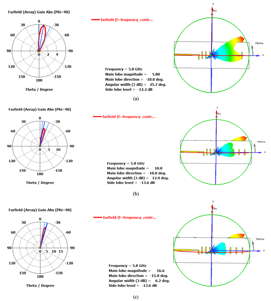
 | Figure A2. Radiation patterns at  for PAA3 (designed with 5.8 GHz square truncated edge-patch antenna). (a) N = 4, (b) N = 8, and (c) N = 16 for PAA3 (designed with 5.8 GHz square truncated edge-patch antenna). (a) N = 4, (b) N = 8, and (c) N = 16 |
 | Figure A3. Radiation patterns at  for PAA4 (designed with 5.8 GHz microstrip-Yagi-Uda dipole antenna). (a) N = 4, (b) N = 8, and (c) N = 16 for PAA4 (designed with 5.8 GHz microstrip-Yagi-Uda dipole antenna). (a) N = 4, (b) N = 8, and (c) N = 16 |
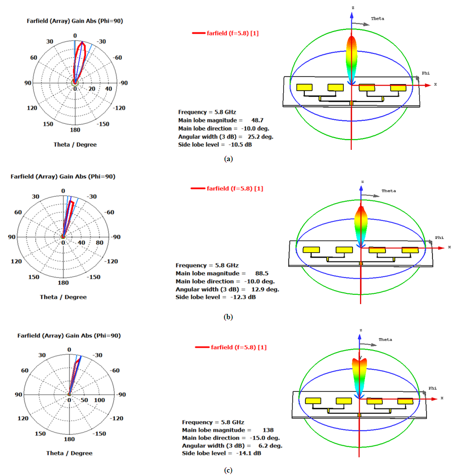 | Figure A4. Radiation patterns at  for PAA5 (designed with 5.8 GHz 4-by-1rectangular patch antenna). (a) N = 4, (b) N = 8, and (c) N = 16 for PAA5 (designed with 5.8 GHz 4-by-1rectangular patch antenna). (a) N = 4, (b) N = 8, and (c) N = 16 |
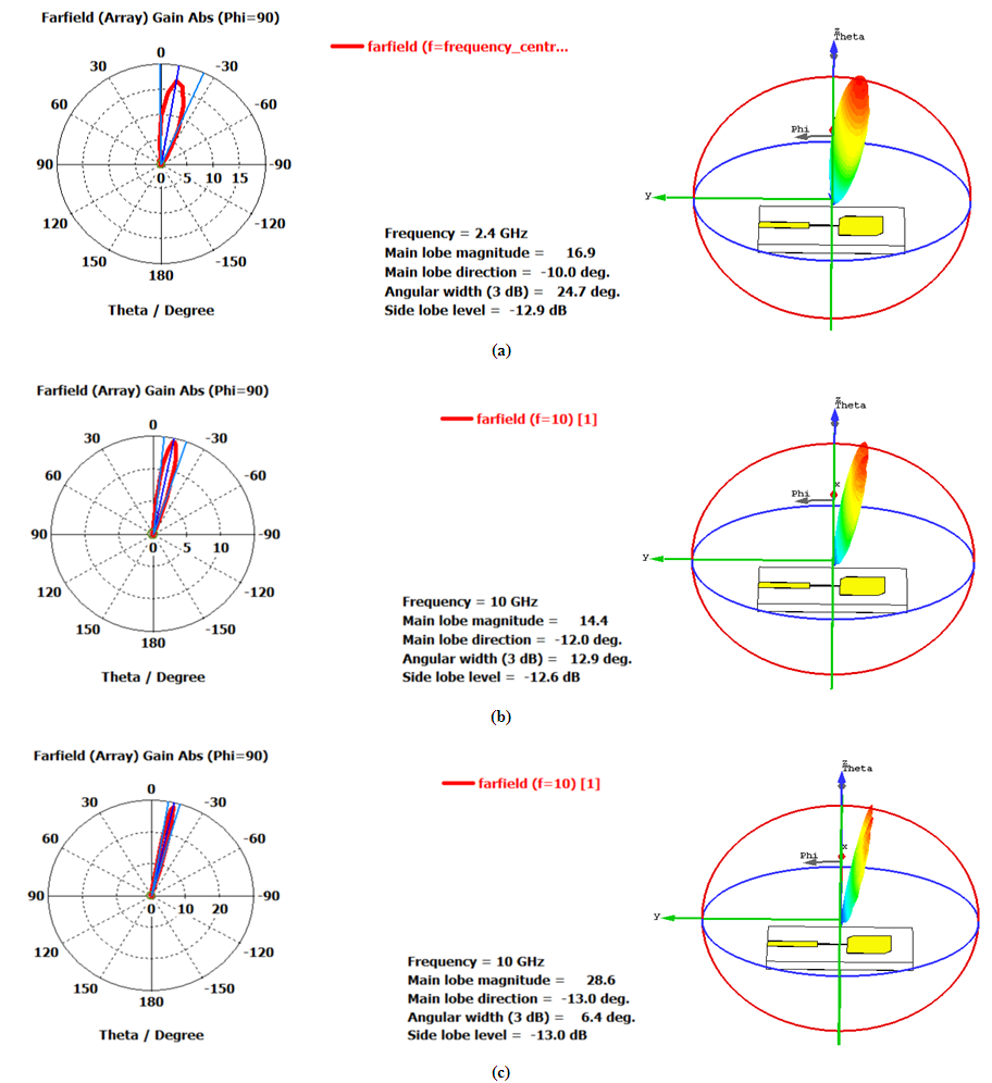 | Figure A5. Radiation patterns at  for PAA6 (designed with 10 GHz square truncated edge-patch antenna). (a) N = 4, (b) N = 8, and (c) N = 16 for PAA6 (designed with 10 GHz square truncated edge-patch antenna). (a) N = 4, (b) N = 8, and (c) N = 16 |
References
| [1] | D. A. K. Aljaf and R. S. Fyath, "Configurable Beam-Steering Network for Phase Array Antennas-Part I: Proposed Configurable Photonic True Time Delay Line", Accepted for publication in International Journal of Networks and Communications, 2019. |
| [2] | D. Marpaung, J. Yao, and J. Capmany, "Integrated Microwave Photonics", Nature Photonics, vol. 13, no. 3, pp. 80- 90, Feb. 2019. |
| [3] | M. Duan and J. Ma, "Optical True Time Delay Unit With Wide Range and High Resolution for Phased Array Beamforming", Photonic Network Communications, 2019-Online. https://link.springer.com/article/10.1007%2Fs11107-018-0816-2. |
| [4] | X. Feng, L. Yan, H. Jiang, P. Li, J. Ye, Y. Zhou, W. Pan, B. Luo, X. Zou and T. Zhou, "Photonic Generation of Multilevel Frequency-Hopping Microwave Signal", IEEE Photonics Journal, vol. 11, no. 1, Article no. 5500207- 5500207, Feb. 2019. |
| [5] | Y. Gu and Jianping Yao, "Microwave Photonic Link With Improved Dynamic Range Through π Phase Shift of the Optical Carrier Band", IEEE Journal of Lightwave Technology, vol. 37, no. 3, pp. 964- 970, Feb. 2019. |
| [6] | R. Maram, S. Kaushal, J. Azana, and L. R. Chen, "Recent Trends and Advances of Silicon-Based Integrated Microwave Photonics", Photonics Journal, vol. 6, no. 1, pp. 1-40, Jan. 2019. |
| [7] | Y. Shen, X. Meng, Q. Cheng, S. Rumley, N. Abrams, A. Gazman, E. Manzhosov, M. S. Glick, and K. Bergman, "Silicon Photonics for Extreme Scale Systems", IEEE Journal of Lightwave Technology, vol. 37, no. 2, pp. 245- 259, Jan. 2019. |
| [8] | B. E. Caroline, S. C. Xavier, A. P. Kabilan, and J. William, "Performance analysis and comparison of optical signal processing beamforming networks: a survey", Photonic Network Communications, vol. 37, no. 1, pp. 38-52, Feb. 2019. |
| [9] | L. Huang, P. Dai, and X. Chen, "Signal-to-Noise Ratio of True-Time Delay Beamformers Based on Microwave Photonic Links Using an Incoherent Broadband Optical Source", Journal of Quantum Electronics, vol. 55, no. 1, Article no. 8700109, pp. 1-9, Feb. 2019. |
| [10] | J. Yao, "Microwave Photonics", IEEE Journal of Lightwave Technology, vol. 27, no. 3, pp. 314-335, Feb. 2009. |
| [11] | https://optiwave.com. |

 Abstract
 Reference
 Full-Text PDF
 Full-text HTML