-
Paper Information
- Paper Submission
-
Journal Information
- About This Journal
- Editorial Board
- Current Issue
- Archive
- Author Guidelines
- Contact Us
International Journal of Networks and Communications
p-ISSN: 2168-4936 e-ISSN: 2168-4944
2019; 9(1): 1-22
doi:10.5923/j.ijnc.20190901.01

Performance Investigation of Unamplified C-Band Nyquist 16-QAM Half-Cycle Transmission for Short-Reach Optical Communications
 Abstract
 Reference
 Full-Text PDF
 Full-text HTML
Mays M. Ibrahim, Raad S. Fyath
Department of Computer Engineering, Al-Nahrain University, Baghdad, Iraq
Correspondence to: Mays M. Ibrahim, Department of Computer Engineering, Al-Nahrain University, Baghdad, Iraq.
| Email: |  |
Copyright © 2019 The Author(s). Published by Scientific & Academic Publishing.
This work is licensed under the Creative Commons Attribution International License (CC BY).
http://creativecommons.org/licenses/by/4.0/

This paper investigates the transmission performance of 16-QAM Nyquist half-cycle single-side band transmission over unamplified C-band optical fiber link. The system uses optical carrier assisted intensity modulation/direct detection scheme with digital signal processing unit is employed in the receiver to compensate fiber dispersion and nonlinear optics effect. Expressions are derived to assess the noise and bit error rate (BER) characteristics of the receiver. Results are presented to address the effect of the assisted optical carrier on the BER performance of 56, 112, 224 Gbps receivers. Simulation results are presented for 112 and 224 Gbps single-channel system to address the effect of various system parameters on the maximum reach. Then the simulation is extended to WDM system incorporating with 112 and 224 Gbps channel data rates. Simulation results obtained using Optisystem software reveal that a maximum reach of 86 and 65 km is achieved for 32×112 Gbps (≈ 3.6 Tbps) and 32×224 Gbps (≈ 7.2 Tbps) system, respectively, with 0 dBm signal and carrier lasers powers.
Keywords: Nyquist half cycle optical communication, Unamplified C-band, 16-QAM IM/DD, Optical SSB 16-QAM
Cite this paper: Mays M. Ibrahim, Raad S. Fyath, Performance Investigation of Unamplified C-Band Nyquist 16-QAM Half-Cycle Transmission for Short-Reach Optical Communications, International Journal of Networks and Communications, Vol. 9 No. 1, 2019, pp. 1-22. doi: 10.5923/j.ijnc.20190901.01.
Article Outline
1. Introduction
- The demand for high-capacity communication services continues to grow at around 30% to 60% per year with increase data delivery in both long-haul backbone and short-haul optical network [1-3]. This capacity demand has attracted intense research on high-spectral efficiency (SE) optical communication networks [4-8]. To increase the SE of these networks, high-order modulation formats such as quadrature-amplitude modulation (QAM) have been employed [4, 5] and supported by advanced multiplexing techniques such as orthogonal frequency-division multiplexing (OFDM) [9, 10] and Nyquist wavelength-division multiplexing (WDM) [11-13]. The operation of high-data rate long-haul and metro optical networks are mainly based on coherent receivers which require complex hardware including local laser to act as a local oscillator, balanced photodiode (PD) configuration, and analog-to-digital converters (ADCs) [14-17]. The expense of coherent receiver-based scheme can be shared by a large number of subscribers which makes this high-efficiency scheme suitable for such types of optical networks. In contrast, short-reach optical network serves fewer subscribers and hence the cost and complexity of coherent detection less justifiable here. Therefore, intensity modulation/direct detection (IM/DD) schemes have attracted increasing interest for short-range applications [18-20]. The DD system only needs one single-ended PD and one ADC for each polarization in the receivers and hence it is characterized by low cost and easy integration [14, 21].Various modulation techniques have been used for IM/DD-based short-reach optical networks [21]. Among these techniques are multilevel pulse amplitude modulation (PAM) [22-24], OFDM [24, 25], carrierless amplitude/phase (CAP) modulation [26, 27], and QAM with subcarrier modulation (SCM) [28, 29]. In general, OFDM and CAP are more complex than SCM. OFDM uses fast Fourier transform (FFT) and inverse FFT while CAP uses orthogonal filter pairs in the transmitter and receiver [30, 31]. In contrast, SCM can be implemented with relatively low complexities by digital frequency up-conversion without electrical mixer or radio frequency (RF) sources [21]. Further, SCM shares OFDM and CAP by using the complex-valued signal to modulate the subcarrier according to QAM signaling. However, the major limitation of bit rate-transmission distance product of DD optical communication system is fiber chromatic dispersion (CD). The CD introduces spectrally selective power fading distortion due to square-law photodetiction [32]. To reduce the effect of CD, single-sideband (SSB)-SCM rather than double-sideband (DSB)-SCM has been proposed to DD optical communication systems [33-35]. To reduce the effect of CD further, digital Nyquist pulse shaping has been used to realize SCM having subcarrier frequency equals half the symbol rate (half cycle) [14, 21, 36, 37]. The Nyquist half cycle (NHC) SSB–SCM achieves the most efficient bandwidth usage while ensuring zero intersymbol interference (ISI) at the decision detection time at the receiver.In recent years, different research groups have been worked in the analysis, performance evaluation, and demonstration of NHC-SCM. For example, Liu et al. [28] experimentally demonstrated 40 Gbps 16-QAM vestigial sideband NHC-SCM transmission over 100 km dispersion-uncompensated standard single-mode fiber (SSMF). The losses of the fiber were compensated using Er-doped optical amplifier (OA) and the results show that the proposed system out performs DD-optical OFDM. Tang et al. [21] analyzed and demonstrated the transmission of single-polarization (SP) and dual-polarization (DP) 64/128-QAM NHC-SCM over unamplified SSMF. Their results show that when 3 GHz-electrical bandwidth is used, the bit-error rate (BER) of 32.5 Gbps DP 64-QAM format after 20 km fiber transmission is under 3.8×10⁻³, and BER of 38 Gbps DP 128-QAM format is under 2.4×10⁻². In 2016, Zou [14] demonstrated the transmission of 200 Gbps NSC SSB-SCM over 80 km-amplified SSMF using 16-QAM signaling and DP direct detection. In 2017, Zhu et al. [36] demonstrated 224 Gbps 16-QAM NHC SSB-SCM transmission over 160 km amplified SSMF using optical carrier-assisted (OCA) technique. In their experiment, an optical carrier is added using an additional laser at the transmitter side, which is delivered along with the signal. Their results show that OCA-SSB is analogue to heterodyne detection and requires the simplest structure of DD with one single-ended PD and one ADC. A 112 Gbps 16-QAM SSB-SCM was also demonstrated over 960 km-amplified SSMF using NHC signaling and nonlinear distortion suppression technique [34]. The design and fabrication of a silicon photonic in-phase quadrature-phase (IQ) modulator for generating Nyquist shaped SSB signals was reported by Raun et al. [35]. They demonstrated 50 Gbps 16-QAM Nyquist-shaped SSB transmission over 320 km-amplified SSMF. The use of WDM technique to enhance the transmission rate of NHC SSB-SCM system also demonstrated but to a lesser extent. For instance, Zou et al. [32] demonstrated the transmission of 8×100 Gbps 16-QAM NHC signals over 320 km-amplified SSMF. All the references mentioned in the above literature survey use 1550 nm-wavelength or C-band for transmission. For O-band operation, Zhong et al. [37] demonstrated the transmission of 608 (4×152) Gbps 16-QAM NHC-SCM over unamplified SSMF. The maximum transmission distance achieved by the experiment is 10 km for the single-channel (152 Gbps) system and 2 km for the 4-channel WDM system.It is clear from the above survey that most of the work reported in the literature about NHC-based optical communication systems are concerned on the transmission of a single-channel over amplified SSMFs. In these cases, Er-doped OA is inserted after each span of the transmission link to compensate the fiber loss. The OA may be also inserted at the transmitter-end of the fiber to boost the optical signal power or at the receiver-end side of the fiber to yield a preamplified optical receiver. The implementation of Er-doped OA requires a pumping laser source and this will increase the cost and system complexity when short-reach applications are considered. This paper addresses the transmission performance of single-channel and multichannel NHC SSB-SCM over a C-band SSMF-link implemented without optical amplification. The OCA-Nyquist SCM system proposed in [36] is used as the basic system for investigation in this paper. The noise characteristics and sensitivity of the OCA NHC SSB-SCM receiver are addressed analytically. The system is then implemented in Optisystem software environment and used to deduce simulation results describing the transmission performance. Both SP and PD configurations are considered for single-channel transmission and extended for WDM transmission. Simulation results are presented for 16-QAM system operating with bit rates of 56, 112, and 224 Gbps per polarization per wavelength.The rest of the paper is organized as follows. Section two presents brief description and noise modeling for a single-channel NHC-SCM system operating over unamplified 1550 nm optical link. Related design issues and calculated BER characteristics are given in Section 3. Simulation results related to single and WDM transmission are given in Section four and five, respectively. Section six summarizes the main findings of this work.
2. System under Investigation
2.1. System Description
- Figure 1 shows a block diagram of a single-channel OCA-SCM optical communication system implemented using IM/DD scheme. The system is based on NHC-SSB modulation supported by M-QAM signaling. At the transmitter, the input binary data is mapped into M-QAM format. Each of the real and imaginary parts of the QAM symbol is applied a PAM generator whose output passes through a root raised-cosine (RRC) filter to ensure zero ISI at the receiver decision circuit. The filtered versions of the two PAM signals are applied to an RF quadrature modulator. This modulator is driven by an RF subcarrier to modulate the two filtered PAM signals yielding I and Q modulated components. These two components are summed to yield the quadrature modulator output which is used as an electrical modulating waveform to control the intensity of a continuous-wave (CW) laser. This is achieved by using a SSB optical intensity modulator driven by quadrature modulated electrical signal to modulate the intensity of the CW laser field passing through it. This laser is called the signal laser to distinguish it from another laser used in the system. This SSB optical modulator is implemented here using a conventional DSB optical modulator followed by a high-order optical bandpass filter (OBPF) to select one of the two generated optical SSB.
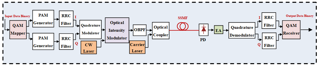 | Figure 1. Block diagram of optical-carrier assisted intensity modulation/direct detection (IM/DD) system incorporating Nyquist half-cycle (NHC) single-sideband (SSB) modulation format. PAM: Pulse amplitude modulation; RRC: Root raised-cosine; CW: Continuous-wave; OBPF: Optical bandpass filter; PD: Photodiode; EA: Electronic amplifier |
2.2. System Model
- Let Rb and Rs denote bit rate and QAM symbol rate, respectively. For a QAM modulation format dealing with M discrete symbol, Rs=Rb/log2M. Let the RRC filter is designed with r roll-off factor. The DSB-bandwidth of modulated RF subcarrier is given by 2[(1+r)Rs/2]=(1+r)Rs. When r=0, NHC shaping is achieved which has a rectangular-spectrum filter characteristic (see Fig. 2a). After optical intensity modulation, the RF signal spectrum appears as a lower sideband (LSB) and upper sideband (USB) around the signal laser frequency ƒs (see Fig. 2b). A high-order OBPF of bandwidth equals (1+r)Rs is used to select one of the sidebands. The LSB is choose in this work as illustrated in Fig. 2c. The field of the CW carrier laser operating with frequency ƒc=ƒs+Rs/2 is add with the LSB component of modulated optical signal to composite the transmitter optical waveform (Fig. 2.d).
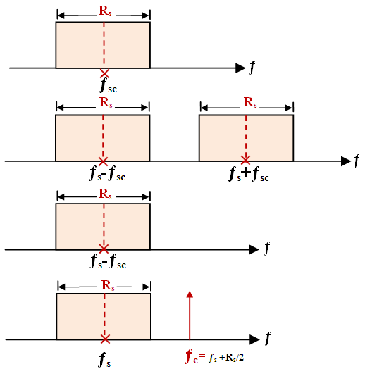 | Figure 2. Illustrative spectral shapes showing the concept of NHC-SSB optical transmitter operating with OCA-technique and r=0. (a) Modulated RF subcarrier. (b) Output of the optical intensity modulator. (c) Lower SSB of the modulated optical signal. (d) Combined optical signal lunched into the fiber |
 | (1) |
 | (2a) |
 | (2b) |
 | (3) |
 | (4) |
 | (5) |
 | (6) |
 | (7a) |
 | (7b) |
 | (7c) |
 | (8) |
 | (9a) |
 | (9b) |
 | (10a) |
 | (10b) |
 | (10c) |
 | (10d) |
 | (11) |
 | (12a) |
 | (12b) |
 | (13) |
 | (14) |
 | (15) |
 | (16) |
 | (17) |
 | (18) |
2.3. Remarks
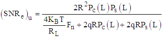
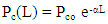
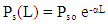
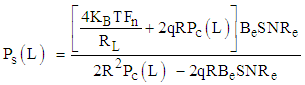
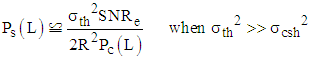
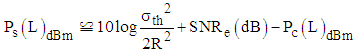
- Few remarks are given here corresponding to the case when the unamplified link is supported by carrier laser inserted at the transmitter side. These remarks are based on eqns. 14 and 16.(i) For a given carrier power Pc the received signal power required to achieve a certain BER level is given by
 | (19a) |
 | (19b) |
 | (20) |
 | (21a) |
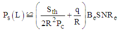
 Note that for a given BER (i.e., given SNRe) increasing Pc(L)dBm by a certain amount (i.e., ∆(dBm)) will reduce the required value of Ps (in dBm) by the same amount (i.e., ∆(dBm)).
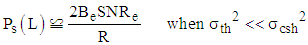 | (21b) |
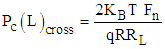 (iv) The value of Pc(L)dBm required to achieve a certain BER level increases linearly with logBe when the modulated format is fixed. Therefore, the required Ps(L)dBm increases by 3 dBm when the bit rate doubles.
3. BER Characteristics
3.1. Design Issues
- Ideally, the RF quadrature modulator in the transmitter side should use a rectangular-shape RRC filter having a bandwidth BRRCF=Rs/2 (i.e., r=0) and RF subcarrier of frequency ƒsc=Rs/2. For practical implementation, a small value of the roll-off factor r is used such as r = 0.02 to ensure that the spectrum of the output waveform of the RRC filter does not have completely Sharpe transition. This is useful to select efficiently one of the SSB components later. In this case,
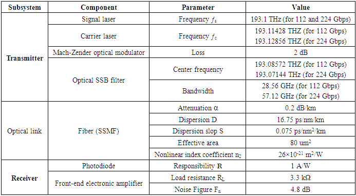
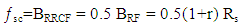 Note that the bandwidth of the modulated RF carrier BRF=2BRRCF since it carries both the upper and lower SSBs (see Fig. 2). The optical modulator shifts the RF spectrum to the optical-frequency domain. The modulated optical carrier has a DSB/SC spectrum with lower and upper sidebands, each carries a copy of the RF signal spectrum. A residual optical carrier at the optical frequency ƒs may exist if the optical modulator is not well-designed for DSB/SC operation and this residual carrier can be rejected by the high-order optical SSB filter. The spectrum of the lower optical SSB extends from a low frequency ƒL = ƒs-2[0.5(1+r)Rs] = ƒs-(1+r)Rs to a high frequency ƒh=ƒs. The OBPF used to select this sideband is characterized by a center frequency ƒOBPF = (ƒL+ƒh)/2 = ƒs-0.5(1+r)Rs and bandwidth BOBPF= (1+r)Rs. The OCA laser frequency is set to ƒs+0.51Rs.For example, consider a 1553.5 nm (193.1 THz) 16-QAM NHC system operating with 224 Gbps bit rate. The symbol rate Rs= Rb/log216 = Rb/4=56 GSps. For r=0.02, ƒsc= (1+r)Rs =28.56 Gbps.The bandwidth of the modulated RF carrier BRF=2×28.56 GHz=57.12 GHz. The bandwidth and center frequency of the optical SSB filter are, respectively, 57.12 GHz and ƒOBPF = ƒs-0.5(1+r)Rs=193.1-28.56×10-3=193.07144 THz. The filter center wavelength λOBPF =c/ƒOBPF =1553.829 nm.
 3.2. Calculated BER Characteristics
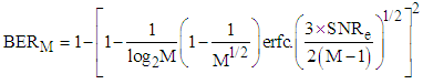
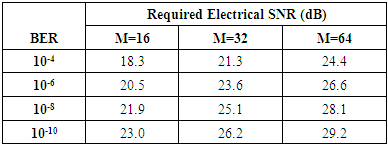
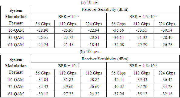
- In this subsection, the BER characteristics of M-QAM NHC-SCM receiver is presented for different values of received signal power Psr, received carrier power Pcr, number of discrete levels M (16, 32, and 64), and bit rate (56, 112 and 224 Gbps). Figure 3 illustrates the variation of BER with electrical SNR and calculated using eqn. 18 for different values of M. Note that at a fixed value of SNRe, the results are independent of bit rate, Psr, and Pcr since these three parameters determine the level of SNRe used in this equation. Table 1 is deduced from Fig. 3 and shows the values SNRe required to achieve BER=10-4, 10-6, 10-8, and 10-10 for the three values of M.
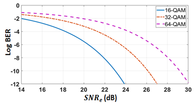 | Figure 3. Variation of BER with received electrical SNR for M-QAM system |
|
|
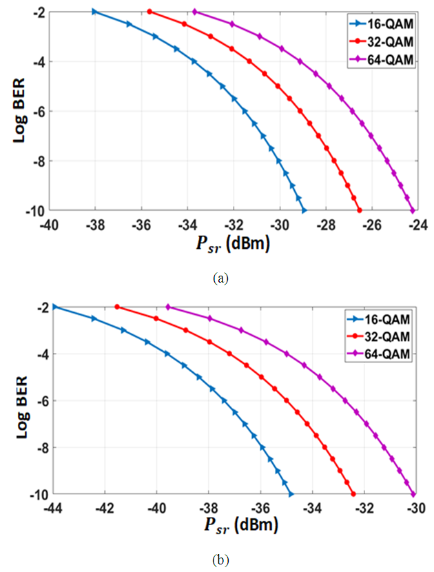 | Figure 4. Dependence of BER on received signal power for 56 Gbps system. (a) Pcr=10 µw. (b) Pcr=100 µw |
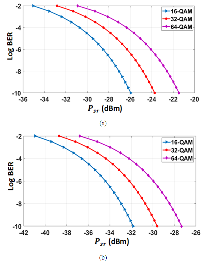 | Figure 5. Dependence of BER on received signal power for 112 Gbps system. (a) Pcr=10 µw. (b) Pcr=100 µw |
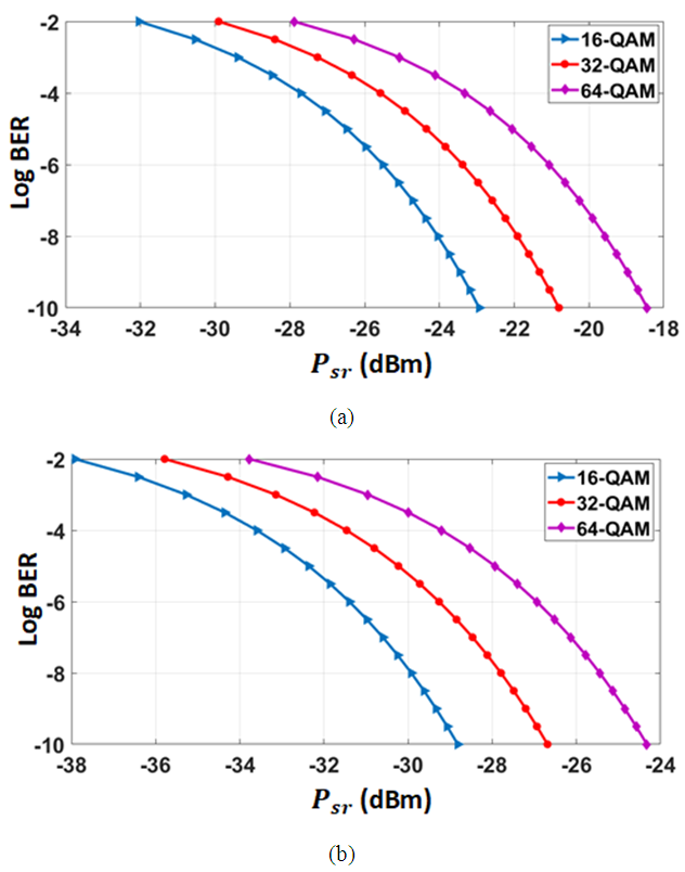 | Figure 6. Dependence of BER on received signal power for 224 Gbps system. (a) Pcr=10 µw. (b) Pcr=100 µw |
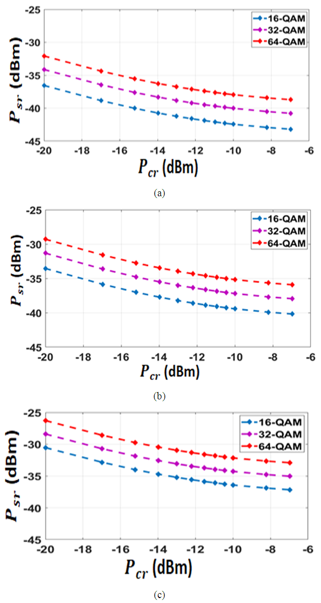 | Figure 7. Receiver Pcr-Psr characteristics when the carrier laser is inserted at the transmitter side. (a) Rb=56 Gbps. (b) Rb=112 Gbps. (c) Rb=224 Gbps |
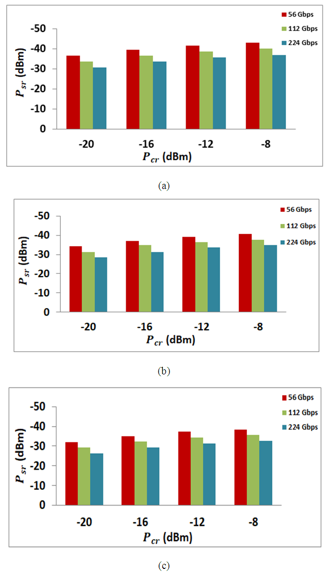 | Figure 8. Values of Psr required to achieve a BER=4.5×10⁻³ at different bit rates. (a) 16-QAM. (b) 32-QAM. (c) 64-QAM |
4. Results for Single-Channel System
- This section presents simulation results describing the transmission performance of a single-channel NHC communication system operating at 1550 nm wavelength without optical amplification. The system is based on SSB-SCM scheme with optical carrier-assisted technique. The results are reported for both 112 and 224 Gbps data rates and for 16-QAM signaling. Unless otherwise stated, the values of the main system parameters used in the simulation are listed in Table 3. A BER threshold (BERth) of 4.5×10⁻³ is used to estimate the maximum allowable transmission distance Lmax from the simulation tests.
|
4.1. Performance of 224 Gbps System
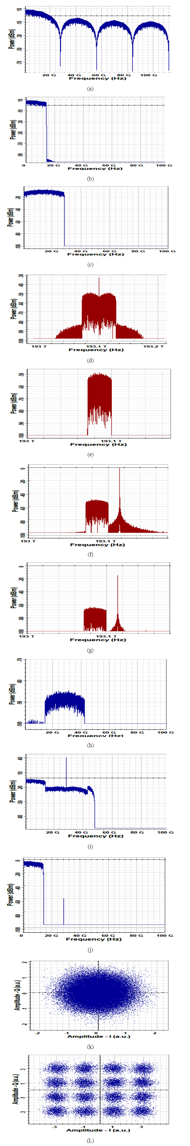
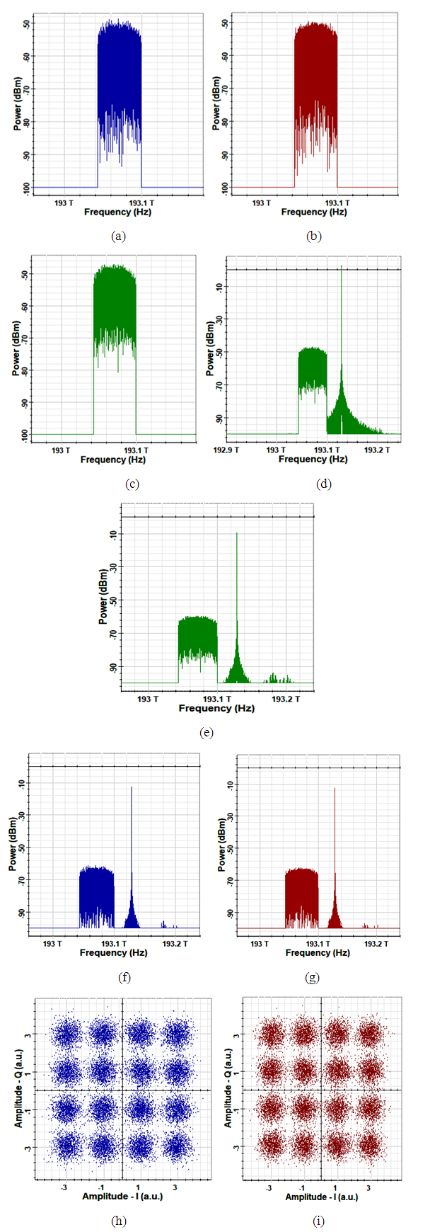
- Figure 9 shows the electrical and optical spectra at different points in the 224 Gbps 16-QAM system. The results are presented for 0 dBm signal laser and 0 dBm carrier laser (inserted in the transmitter side). A 62 km of SSMF is used here which corresponds to Lmax when Pc=Ps=0 dBm. Figure 9 contains also the receiver constellation diagrams before and after the receiver DSP unit. Figure 9a shows the spectrum of the I-electrical QAM pulse generator. The spectrum contains a baseband component covers the frequency range from 0-56 GHz. Note that the 56 GHz corresponds to the symbol rate Rs=Rb/4. The spectrum also contains high frequency components extending above 56 GHz. The Nyquist shaping filter used in the QAM modulator gives an output electrical signal whose spectrum is limited to Rs/2=28 GHz (see Fig. 9b). The RF QAM modulator uses ƒSCM=28 GHz and yields a DSB/SC signal at its output whose spectrum extends from 0-56 GHz (see Fig. 9c). This signal is used to modulate the signal laser leading to an optical DSB waveform whose spectrum is illustrated in Fig. 9d. This optical spectrum indicates that there are LSB and USB components (each of 56 GHz bandwidth) in additional to a residual optical carrier. The optical SSB chooses the LSB component (Fig. 9e) which is combined with the carrier laser field using an optical coupler before launching into the fiber input (Fig. 9f). The spectrum of the received optical waveform is given in Fig. 9g and can be considered as a copy of the spectrum at the fiber input except the signal and carrier power levels are reduced due to fiber loss. The peak of the signal and carrier spectrum is reduced by about 12.4 dB after transmission over the 62 km link and this corresponds to the total loss of this link which has 0.2 dB/km attenuation parameter.Figure 9h displays the spectrum of the amplified photo generated current waveform which has a DSB/SC spectrum around the 56 GHz RF subcarrier with each sideband has 28 GHz bandwidth. The RF QAM demodulator down converts the signal spectrum to the baseband (Fig. 9i) and the required spectrum (0-28 GHz) is obtained after filtering (see Fig. 9j). The constellation diagram at the QAM demodulator output is displayed in Fig. 9k and indicates clearly the presence of random phase effect which comes from the fiber dispersion. The effect of dispersion is compensated using DSP which leads to a clear 16-QAM constellation diagram as shown in Fig. 9L.
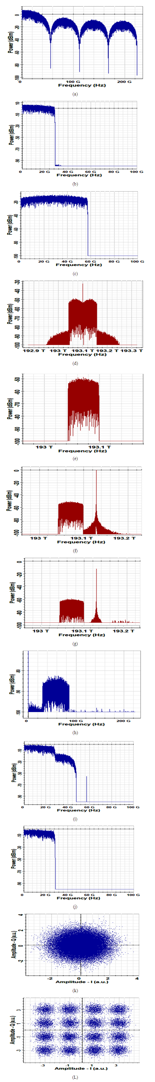 | Figure 9. Spectra and constellation diagrams related to 224 Gbps 16-QAM system operating at 1550 nm band with L=62 km, Ps=0 dBm and Pc=0 dBm (carrier at transmitter). (a) Spectrum of the QAM pulse generator output (I-phase component). (b) Spectrum of the QAM modulator input. (c) Spectrum of the QAM modulator output. (d) Spectrum of the optical modulator output. (e) Spectrum of the optical SSB signal. (f) Spectrum of signal SSB + assisted carrier. (g) Spectrum of the optical signal at the fiber output. (h) Spectrum of the amplified photocurrent. (i) Spectrum of the QAM demodulator output. (j) Spectrum of the filtered QAM demodulator output. (k) Receiver constellation diagram at the DSP input. (L) Receiver constellation diagram at the DSP output |
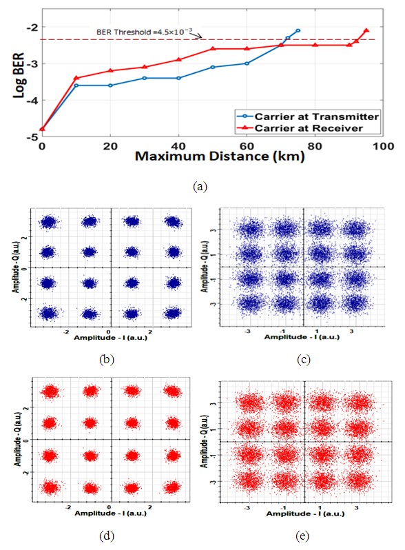
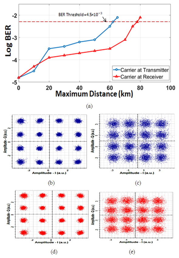 | Figure 10. (a) Dependence of BER on transmission distance for 224 Gbps 16-QAM system operating with 0 dBm signal launch power and 0 dBm carrier power. (b) Receiver constellation diagram for B2B transmission (carrier at the transmitter). (c) Receiver constellation diagram after 62 km transmission (carrier at the transmitter). (d) Receiver constellation diagram for B2B transmission (carrier at the receiver). (e) Receiver constellation diagram after 78 km transmission (carrier at the receiver) |
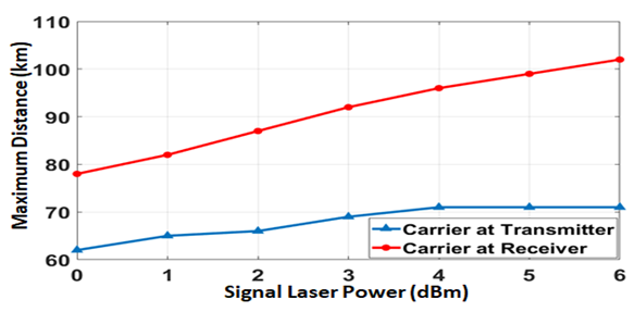 | Figure 11. Variation of maximum reach Lmax with signal laser power Ps assuming 224 Gbps 16-QAM system operating with Pc=0 dBm |
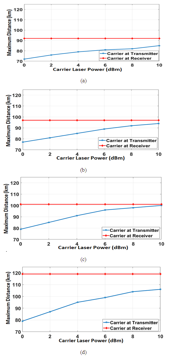
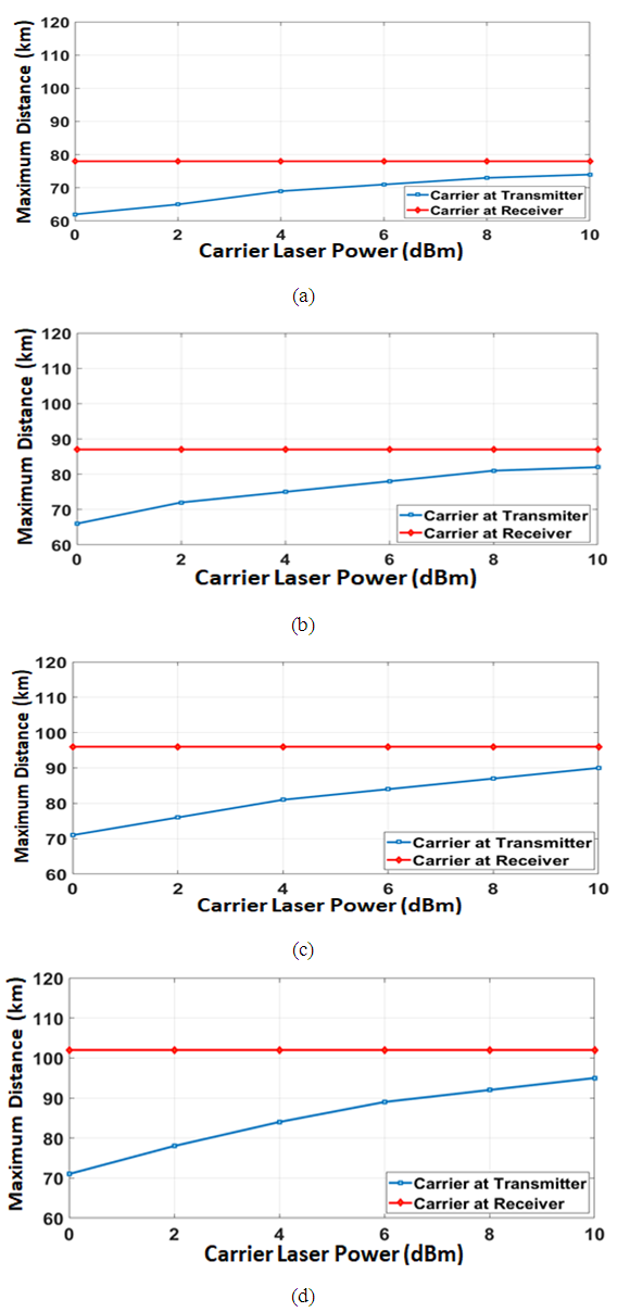 | Figure 12. Dependence of maximum transmission distance on carrier laser power for 224 Gbps 16-QAM system. (a) Ps=0 dBm. (b) Ps=2 dBm. (c) Ps=4 dBm. (d) Ps=6 dBm |
|
4.2. Performance of 112 Gbps System
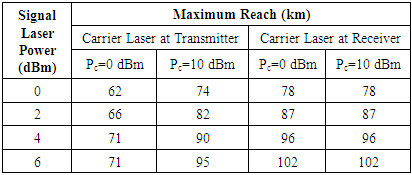
- The simulation tests of section 4.1 are repeated for 112 Gbps 16-QAM system and the results are adapted in Figs. 13-15 and Table 5. The electrical and optical spectra at different points of the system is given in Fig. 13 and indicate clearly that the transmitter Nyquist shaping filter limits the spectrum of its output waveform to 14 GHz (=Rs/2=Rb/8). When Ps=Pc=0 dBm, the maximum reach is 72 and 92 km depending on the location of the carrier laser (in the transmitter or receiver, respectively), (see Fig. 14). These two values are to be compared with 62 and 78 km for the 224 Gbps counterpart, respectively. Table 5 lists the maximum reach for different values of Ps when Pc=0 and 10 dBm. The table can be used to estimate the optimum value of signal laser power, (Ps)opt. The value of (Ps)opt in dBm, when the carrier laser is inserted in the transmission side, gives the highest value of reach, Lopt, which equals 79 km. When the carrier laser is used at the receiver side, (Ps)opt=8 dBm and gives Lopt=122 km. Note that the values of (Ps)opt are almost identical for both 112 and 224 Gbps systems.
|
 | Figure 13. Spectra and constellation diagrams related to 112 Gbps 16-QAM system operating at 1550 nm band with L=72 km, Ps=0 dBm and Pc=0 dBm (carrier at transmitter). (a) Spectrum of the QAM pulse generator output (I-phase component). (b) Spectrum of the QAM modulator input. (c) Spectrum of the QAM modulator output. (d) Spectrum of the optical modulator output. (e) Spectrum of the optical SSB signal. (f) Spectrum of signal SSB + assisted carrier. (g) Spectrum of the optical signal at the fiber output. (h) Spectrum of the amplified photocurrent. (i) Spectrum of the QAM demodulator output. (j) Spectrum of the filtered QAM demodulator output. (k) Receiver constellation diagram at the DSP input. (L) Receiver constellation diagram at the DSP output |
 | Figure 14. (a) Dependence of BER on transmission distance for 112 Gb/s 16-QAM system operating with 0 dBm signal launch power and 0 dBm carrier power. (b) Receiver constellation diagram for B2B transmission (carrier at the transmitter). (c) Receiver constellation diagram after 72 km transmission (carrier at the transmitter). (d) Receiver constellation diagram for B2B transmission (carrier at the receiver). (e) Receiver constellation diagram after 92 km transmission (carrier at the receiver) |
 | Figure 15. Dependence of maximum transmission distance on carrier laser power for 112 Gbps 16-QAM system. (a) Ps=0 dBm. (b) Ps=2 dBm. (c) Ps=4 dBm. (d) Ps=6 dBm |
4.3. Summary
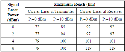
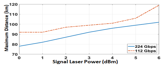
- Figures 16 and 17 give summary for the transmission performance comparison between the 112 and 224 Gbps 16-QAM system. Figure 16 displays the dependence of the maximum reach on signal power Ps when the carrier laser is in the transmitter side. The simulation is repeated in Fig. 17 assuming the carrier laser is inserted at the receiver side. In both figures, the value of Ps is limited to (Ps)opt corresponding to the case under observation. Investigation of the results of Fig. 16 reveals the following findings. At fixed values of Pc and Ps, the maximum reach of the 112 Gbps system is about 10 km higher than that of 224 Gbps system. When Ps=0 dBm, the highest values of Lmax equals 85 and 74 km for the 112 and 224 Gbps system, respectively. Thus transmission distance above 100 km cannot be achieved under these conditions. Increasing Ps to 6 dBm increases Lmax to 106 and 95 km for the 112 and 224 Gbps system, respectively, when Pc=10 dBm. Note further transmission distance above 100 km cannot be achieved for 224 Gbps system. The maximum reach of the 112 Gbps system approaches 100 km when Ps=4 dBm and Pc=10 dBm. When the carrier laser is inserted in the receiver side, the Lmax-Ps relation becomes almost insensitive to value of Pc. Therefore, Fig. 17 is presented for a simple case (Pc=0 dBm) and indicates that Lmax=92 and 78 km for 112 and 224 Gbps, respectively, when Ps=0 dBm. Increasing Ps to 6 dBm increases Lmax to 119 and 102 km, respectively.
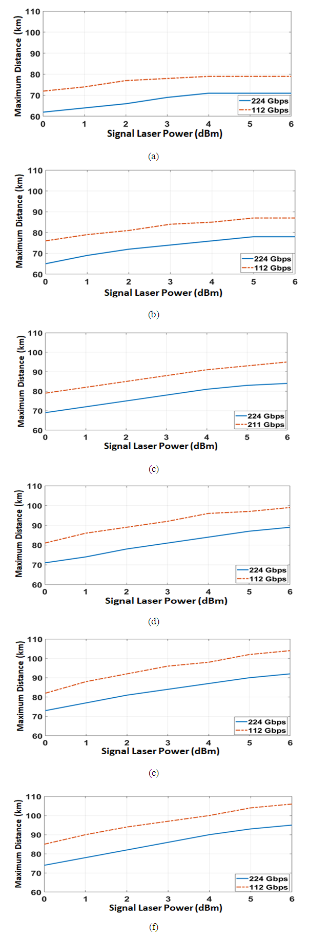 | Figure 16. Variation of maximum distance with signal laser power for 16-QAM system operating with carrier laser inserted at the transmitter side. (a) Pc=0 dBm. (b) Pc=2 dBm. (c) Pc=4 dBm. (d) Pc=6 dBm. (e) Pc=8 dBm. (f) Pc=10 dBm |
 | Figure 17. Variation of maximum distance with signal laser power for 16-QAM system operating with 10 dBm carrier laser inserted at the receiver side |
5. Capacity Enhancement of NHC System Using Multiplexing Techniques
- This section presents feasibility study for enhancing the transmission data rate of NHC system using multiplexing techniques and addressees the transmission performance of the generated multiplexed systems. Both polarization-division multiplexing (PDM) technique, i.e., DP configuration, and WDM technique are used. The results are reported for SSB 16-QAM NHC systems operating at 224 and 112 Gbps per channel without using optical amplification.
5.1. Polarization-Division Multiplexing System
5.1.1. System Configuration
- Polarization-division multiplexing technique has been used widely in advanced coherent-detection optical communication systems to double the transmission data rate and hence yields double spectrum efficiency [41, 42]. In this technique, each of two data source is used to modulate one of the two orthogonally polarized components of the laser field. The system is equivalent to transmitting two channels in parallel through the fiber using only one transmitter laser. In coherent optical communication systems, the state of polarization (SOP) of the local laser used in the receiver should match the SOP of the transmitter laser. However, optical fibers suffer from polarization dispersion effect where the two orthogonally polarized optical components do not travel at the same speed on the fiber. This makes the SOP of the received optical signal differs from its SOP at the fiber input. Therefore, matching between the SOPs of the received optical signal and the local laser field should be controlled and updated continuously. This increases the cost and the complexity of the receiver. In this subsection, the concept of PDM is applied to SSB NHC system operating with carrier assisted laser inserted at the transmitter side. Since in this configuration both signal and carrier lasers are at the transmitter, the optical fiber will alter their SOPs by the same amount and therefore, static SOP matching technique can be adopted at the transmitter.Figure 18 gives a simplified diagram describing the concept of a dual-polarization NHC communication system. The SOPs of both signal and local laser fields are controlled to yield linearly polarized fields with 45° polarization angle. The 45° ensures that the optical powers of the two orthogonal components of each field are equal.
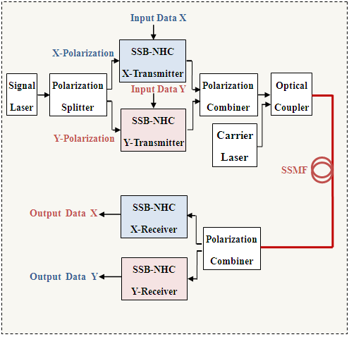 | Figure 18. Block diagram of a dual-polarization NHC communication system. SSB: Single side-band; NHC: Nyquist half-cycle |
5.1.2. Simulation Results
- This subsection presents simulation results related to 2×224 Gbps dual-polarization SSB 16-QAM NHC system operating at the 1550 nm window without optical amplification. Different simulation tests are performed to address the maximum reach corresponding to different values of Pc and Ps. The results reveal that one can get almost the same value of the maximum reach obtained in the 224 Gbps SP counterpart when the signal and carrier lasers powers are doubled. This is clearly noted from Fig. 19 where the maximum reach Lmax for DP system is plotted versus signal laser power and for different values of carrier laser power. Pc-DP Results corresponding to SP system are also included in this figure for comparison purpose and estimated when both lasers powers are half that of the DP counterpart. [Ps-DP=Ps-SP+3 (dBm) and Pc-DP=Pc-SP+3 (dBm)].
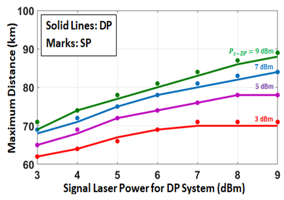 | Figure 19. Variation of maximum reach of the 2×224 Gbps dual-polarization 16-QAM system with both signal laser power Ps-DP and carrier laser power Pc-DP. The marks correspond to a single-polarization system operates with half the DP lasers powers (Ps-SP=0.5 Ps-DP and Pc-SP=0.5 Pc-DP) |
 | Figure 20. Spectra and constellation diagrams related to 2×224 Gbps DP 16-QAM system operating at 1550 nm with L=62 km, Ps=3 dBm and Pc=3 dBm (carrier at transmitter). (a) Spectrum of the signal at the X-transmitter output. (b) Spectrum of the signal at the Y-transmitter output. (c) Spectrum of the signal at the output of the transmitter polarization combiner. (d) Spectrum of the optical signal at the fiber input. (e) Spectrum of the optical signal at the fiber output. (f) Spectrum of the received signal at the X-receiver. (g) Spectrum of the received signal at the Y-receiver. (h) Receiver constellation diagram at the DSP output at the X-receiver. (i) Receiver constellation diagram at the DSP output at the Y-receiver |
5.2. Nyquist-Half Cycle WDM System
- This subsection investigates the possibility of using WDM technique to enhance the capacity of SSB 16-QAM NHC system operating with 112 or 224 Gbps per channel data rate. The WDM system operating in the C-band using unamplified SSMF link.
5.2.1. System Configuration and Design Issues
- Figure 21 shows a simplified block diagram for the NHC WDM system under investigation. Each channel operates with OCA-scheme where the carrier laser is inserted in the optical receiver. Inserting the carrier laser in the channel transmitter side is almost impossible due to the presence of neighbouring optical channels. The N-channel WDM transmitter consists of N SSB NHC single-channel transmitters, each operates with its own signal laser and signal date. The N signal lasers have different C-band wavelengths but with fixed frequency channel spacing Δƒ. The center frequency of the optical SSB filter in each NHC channel transmitter is adapted according to the symbol rate and signal laser frequency of that channel. The bandwidth of this filter is identical for all channels and set to the symbol rate Rs.
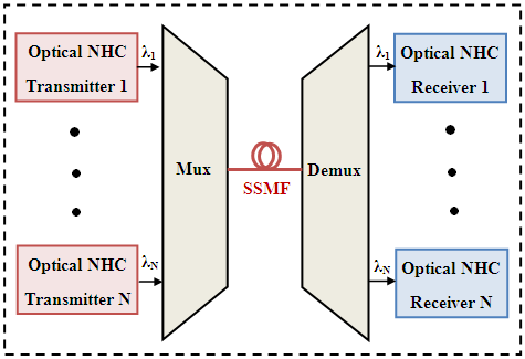 | Figure 21. Block diagram of SSB NHC-based wavelength division multiplexing communication system |
 | (22) |
5.2.2. Simulation Results
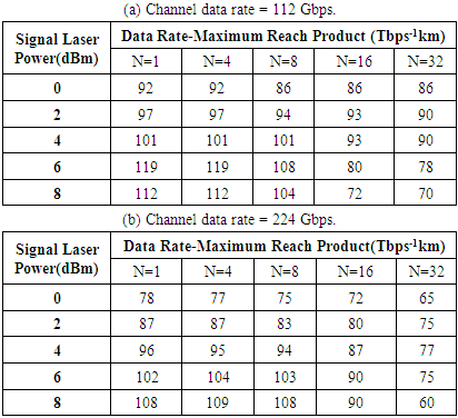
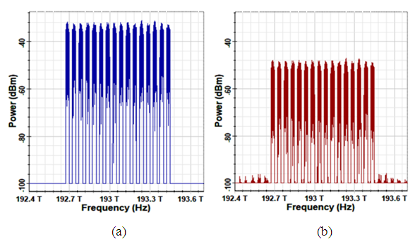
- Simulation results are presented here for SSB 16-QAM NHC system operating with 4-, 8-, 16-, and 32- channel WDM techniques and supported by 0 dBm-OCA scheme. The value of Pc does not affect the maximum reach since the carrier is inserted in the receiver side. The results are reported for both 112 and 224 Gbps channel data rates.The transmission performance of WDM communication systems is usually affected by fiber nonlinear optics and it is mainly due to the dependence of fiber core refractive index on the total intensity of light passing through it and also due to nonlinear fiber scattering effects [4, 10, 43]. In contrast, simulation tests performed on the WDM system under investigation reveal that the effect of fiber nonlinearities are almost negligible even with 16-channel system operating with channel signal laser having 6 dBm power. The reason behind that is that the power of the optical SSB NHC transmitter is much less than the corresponding signal laser power. For example, consider the 16-channel WDM system operating with Ps=6 dBm, 224 Gbps channel data rate, and 16-QAM signaling. The optical modulator used in the system is based on dual-port Mech-Zehnder (MZM) configuration having 2 dB insertion loss. The modulator generates a double-side band (DSB) signal of -6.4 dBm power. The SSB filter chooses one SSB and yields an output signal of -9.5 dBm which is almost half the DSB signal power. The optical power of the WDM waveform at the multiplexer output (which represent the total power launched into the fiber) is found to be 2.5 dBm from the simulation and it corresponds to (-9.5+10log16) dBm. This level of total launch power is relatively low and cannot enhance the effect of nonlinear fiber optics. This conclusion can be deduced from Fig. 22 which compares the optical spectrum of the 16-channel WDM signal at the fiber input with that after 90 km transmission. The results are reported for a system operating with Ps=6 dBm, 16-QAM signaling, and 224 Gbps channel data rate. Note that the signal spectrum at the fiber output matches that at the fiber input from the frequency contents point of view. The level of transmitted signal reduces by 18 dB across the 90 km fiber due to fiber loss (0.2 dB/km).
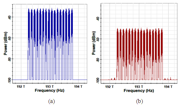 | Figure 22. Optical power spectra corresponding to 16×224 Gbps WDM system operating with 16-QAM signal and Ps=6 dBm. (a) At the fiber input. (b) After 90 km transmission |
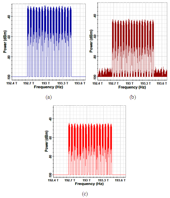
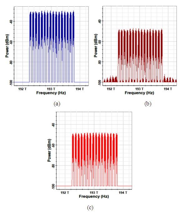 | Figure 23. Optical power spectra corresponding to 16×224 Gbps WDM system operating with 16-QAM signal and Ps= 8 dBm. (a) At the fiber input. (b) After 90 km transmission in the presence of fiber nonlinear optics. (c) After 90 km transmission in the absence of fiber nonlinear optics |
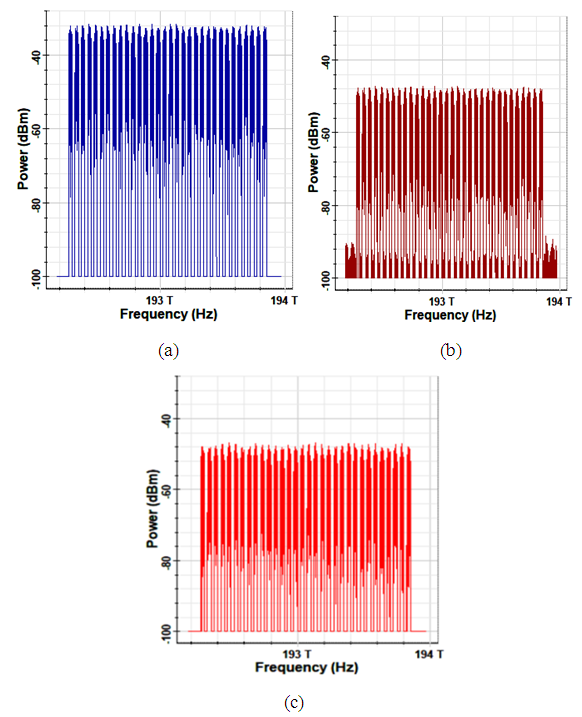
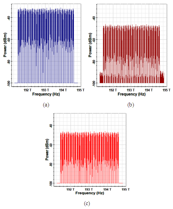 | Figure 24. Optical power spectra corresponding to 32×224 Gbps WDM system operating with 16-QAM signal and Ps=6 dBm. (a) At the fiber input. (b) After 75 km transmission in the presence of fiber nonlinear optics. (c) After 75 km transmission in the absence of fiber nonlinear optics |
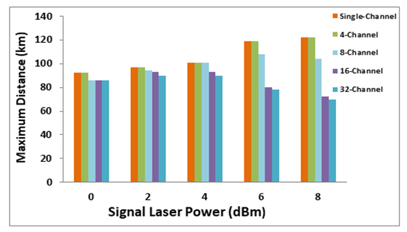
 | Figure 25. Dependence of maximum reach of 16-QAM WDM system on signal laser power and assuming Pc=0 dBm and channel data rate=224 Gbps |
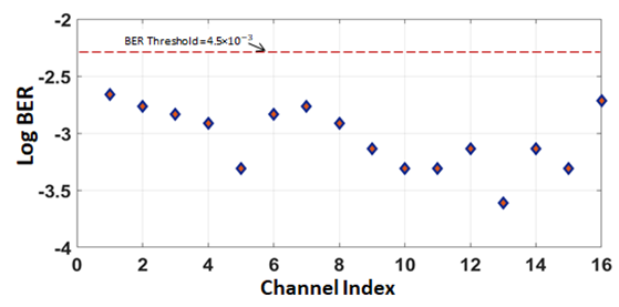 | Figure 26. Variation of BER with channel index for 16-channel WDM system operating with Pc=0 dBm,Ps=6 dBm, Rb=224 Gbps per channel, L=90 km, and 16-QAM signaling |
|
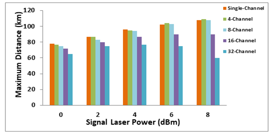
 | Figure 27. Dependence of maximum reach of 16-QAM WDM system on signal laser power and assuming Pc=0 dBm and channel data rate of 112 Gbp |
Appendix Optical Spectra for 112 Gbps
 | Figure 28. Optical power spectra corresponding to 16×112 Gbps WDM system operating with 16-QAM signal and Ps=6 dBm. (a) At the fiber input. (b) After 80 km transmission |
 | Figure 29. Optical power spectra corresponding to 16×112 Gbps WDM system operating with 16-QAM signal and Ps=8 dBm. (a) At the fiber input. (b) After 72 km transmission in the presence of fiber nonlinear optics. (c) After 72 km transmission in the absence of fiber nonlinear optics |
 | Figure 30. Optical power spectra corresponding to 32×112 Gbps WDM system operating with 16-QAM signal and Ps=6 dBm. (a) At the fiber input. (b) After 78 km transmission. (c) After 78 km transmission in the absence of fiber nonlinear optics |
6. Conclusions
- The BER characteristics and transmission performance of unamplified optical carrier assisted NHC-SSB system have been investigated numerically and by simulation. Results have been presented for 16-QAM 1550 nm single-channel and C-band multichannel transmission with channel data rate up to 224 Gbps. The main conclusions of this study are (i) Doubling the bit rate of a given signaling format increase the receiver sensitivity by about 3 dBm.(ii) For giving bit rate, going from 16-QAM to 32-QAM increases the receiver sensitivity by about 2.4 dB. This is to be compared with about 2.3 dB when one goes from 32-QAM to 46-QAM signaling.(iii) The maximum reach Lmax channel increases slightly with signal laser power when the carrier laser is inserted at the transmitter side. (for 62 km at Ps=0 dBm to 71 km at Ps=6 dBm when the carrier laser power Pc=0 dBm). Using the carrier laser at the receiver side increases Lmax notably. (From 78 to 102 km when Ps increases from 0 to 6 dBm).(iv) The effect of fiber nonlinear optics almost negligible for the NHS-SSB WDM system.(v) With Ps=Pc=0 dBm, Lmax equals 86 km for the 32×112 Gbps system and 65 km for the 32×224 Gbps system.