Oluwafemi A. Ilesanmi, Charles U. Ndujiuba
Electrical & Information Engineering, Covenant University, Ota, Nigeria
Correspondence to: Oluwafemi A. Ilesanmi, Electrical & Information Engineering, Covenant University, Ota, Nigeria.
| Email: |  |
Copyright © 2018 The Author(s). Published by Scientific & Academic Publishing.
This work is licensed under the Creative Commons Attribution International License (CC BY).
http://creativecommons.org/licenses/by/4.0/

Abstract
Different dielectric materials affect the electrical characteristics of a patch antenna differently. In this paper, the design frequency and the thickness of the substrate were kept constant, while different substrate materials were used in the design of an inset fed rectangular patch antenna in other to study the effect of these substrate materials on the Gain and radiation pattern of the antenna. Substrate materials like FR4 with dielectric constant of 4.4, Duroid (tm) with dielectric constant of 2.2, Foam with dielectric constant of 1.05 and Neltec NH9348 with dielectric constant of 3.48 were investigated. The antenna was designed and simulated using HFSS software. The result obtained shows that foam, with the least dielectric constant has the highest gain with a wide beam radiation pattern, followed by Duroid, while FR 4 has the least gain.
Keywords:
Substrate, Gain, Radiation Pattern, Patch Antenna
Cite this paper: Oluwafemi A. Ilesanmi, Charles U. Ndujiuba, Effects of Using Different Substrates on the Performance of an Inset-Fed Rectangular Microstrip Patch Antenna, International Journal of Networks and Communications, Vol. 8 No. 2, 2018, pp. 37-41. doi: 10.5923/j.ijnc.20180802.03.
1. Introduction
Antennas play a key role in the present day wireless and mobile communication systems, and microstrip patch antennas are widely deployed in our mobile and portable communication devices because of their small sizes, low production cost, light weight, conformability, ease of fabrication and the ease with which they can be etched on a circuit board. A microstrip Patch is a form of a narrow band with a wide beam antenna, which can be described simply as being made up of a metallic radiating patch and a ground plane each one at one side of a dielectric substrate and a feeding point which can either be connected to the radiating patch directly or indirectly, depending on the feeding method used. They can also be seen as planar resonant cavities that radiates from fringing fields around their edges and which has peak efficiency when its impedance is well matched [1, 6, 8].The radiating patch is made up of a conducting material which can be copper or gold, and different feeding methods can be employed to excite the patch [8, 10]. The substrate is used primarily to provide adequate spacing and mechanical support between the radiating patch and the ground plane. More often, substrate with high dielectric-constant materials are used to load the patch and reduce its size at the expense of the bandwidth and radiation efficiency [13, 14]. While a thicker substrate with lower permittivity gives a better radiation efficiency, improved bandwidth while sacrificing the size [15]. It is therefore very important to carefully select the substrate to use based on the aim of the design. Ideally, the substrate material should have low insertion loss with a loss tangent of less than 0.005 [13]. Microstrip patch antennas are the most versatile and commonest form of etched antennas. They have a lot of advantages when compared with other types of conventional antennas and hence have wide area of applications like mobile and satellite communication, global positioning system and radar application to mention a few.Patch antennas come in different shapes like: rectangular, square, circular, elliptical and triangle and their sizes depend on the thickness of the substrate. The most popular of these are the rectangular and the circular patch antennas and both have wide radiation patterns [5].One major problem associated with a patch antenna is its narrow bandwidth and this limits the range of frequency over which this antenna can perform excellently. A very thick substrate with a low dielectric can be used to get a better performance of wider bandwidth, better radiation and efficiency from this antenna at the expense of the size of the antenna. Also the larger the size of the ground plane, the better the performance of the patch antenna [2, 13].
2. Feeding Techniques
There are different feed techniques that have been employed in patch antenna design in other to improve its performance. This is because if the feeding method is bad, the overall performance and efficiency of the antenna will be low no matter how good the design is [5]. These feed techniques can be broadly categorized as contact and non- contact feed methods. They can also be termed as direct and indirect feed method.In the contact feed, direct connection exists between the feed line and the radiating patch, e.g microstrip line and coaxial feed. While in the non-contact method, the feed line is electromagnetically coupled to the radiating patch e.g proximity coupling and aperture coupling. The various feed techniques are reported in [8].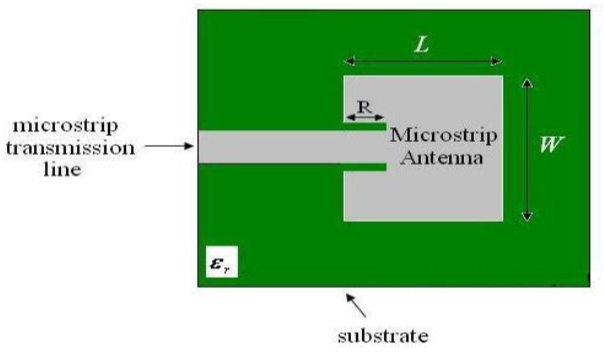 | Figure 1. Microstrip line feed showing edge feed and inset cut feed |
Feed point should be located in such a way as to provide good impedance matching. This is necessary to minimize the return loss of the antenna [12].
3. Design and Methodology
The following equations are used to determine the dimensions of a conventional rectangular patch antenna, following the steps:Determining the width of the patch: the width W is calculated using [5, 9]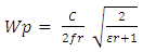 | (1) |
Where, c is the speed of light in free space = (3x10⁸m/s)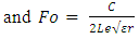 | (2) |
Le being the effective length of the patch and is given as 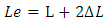 | (3) |
Next is to calculate the effective dielectric constant: 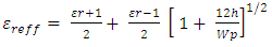 | (4) |
Where εr is the dielectric constant of the substrate and  is the effective dielectric constantNext is to calculate the effective length, which is given as
 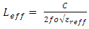 | (5) |
Next step is to determine the extended length of the patch due to the fringing field and it’s given as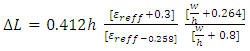 | (6) |
The real length of the patch is given as: 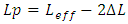 | (7) |
To determine the ground plane dimensions length (Lg) and width (Wg) | (8) |
 | (9) |
Feed point Location of an Inset Fed Rectangular Patch (xo, yo, wf, Lf).There are different methods of feeding a patch antenna like: probe feed, microstrip line feed, aperture coupled feed and proximity coupling feed. But of all, microstrip line feed and the coaxial probe feed are commonly used because of their simplicity.Microstrip inset feed method was used in this design for proper input impedance matching [2] and the line parameters were designed using a standard input impedance of 50Ω. Feed point location where input impedance is approximately 50Ω can be calculated using [3, 4]. | (10) |
where, | (11) |
 | (12) |
 | (13) |
 | (14) |
where 
4. Feed Point Location
Theoretically impedance varies with its peak value at the edges of the patch and reduces to 0Ω at the centre of the patch [12], So it is a bit difficult to locate a feed point with 50Ω impedance on the patch.Feed point location for edge fed patch, where input impedance is approximately 50Ω is given as [7] | (15) |
 | (16) |
Using equations 1-16, antenna dimensions were calculated using matlab.With these antenna dimensions, Fr4, Duroid, Foam and Nectec were used as substrate for four different antenna designs. Using HFSS as the design and simulation software, the result obtained are as shown below.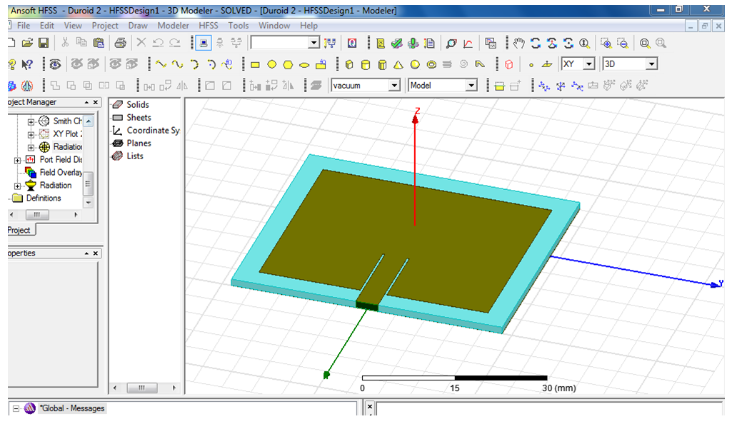 | Figure 2. Rectangular Patch Antenna in HFSS Environment |
5. Result and Analysis
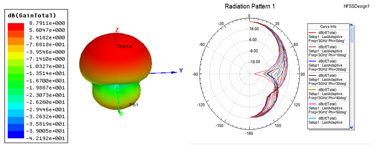 | Figure 3. Gain plot and the radiation pattern of a patch antenna with Foam as Substrate |
Figure 3, above shows that with foam as the substrate the gain of the antenna is 8.7dB and the has a wide beam directional radiation pattern. 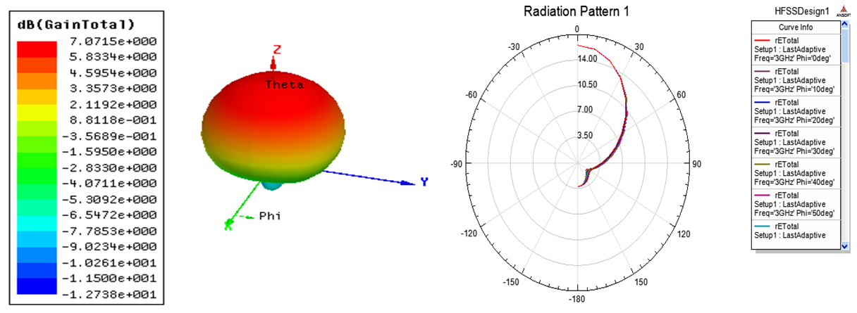 | Figure 4. Gain plot and radiation pattern for a patch antenna with Duroid as Substrate |
Figure 4 above shows that the antenna with duroid as substrate also has a high gain of 7db and highly directional.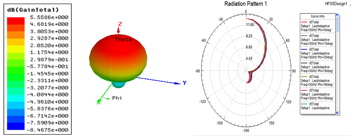 | Figure 5. Gain Plot and radiation pattenr for a Patch antenna with Neltec as Substrate |
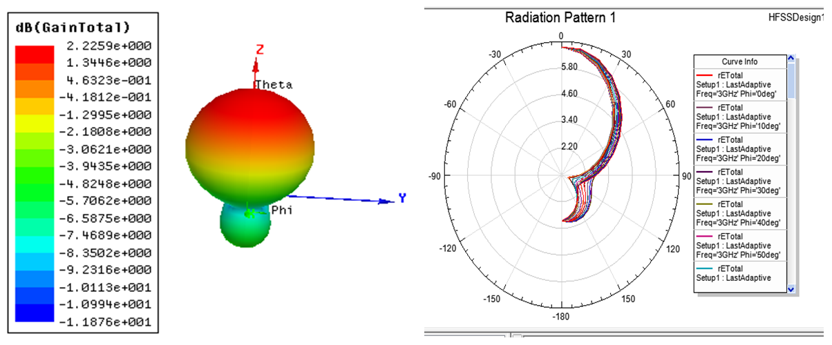 | Figure 6. Gain Plot and radiation pattern for a Patch antenna with FR4 as Substrate |
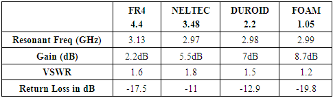
From figure 6, we can see that the gain of this antenna with FR4 as the substrate material is 2.2 dB, which is far lower than the rest.The table below shows the summary of all the results obtained from the simulationsTable 1. Variation of antenna characteristics with different substrate materials
 |
| |
|
6. Conclusions
From the result shown in table 1 above, it can be seen that foam with the least dielectric constant has the highest gain of 8.7dB and also lowest loss with a return loss of -19.8dB. This low loss is also confirmed by the VSWR value of 1.2. It is also evident that the gain of the antenna reduces as the value of the dielectric constant increases, from 8.7dB for Foam to 2.2dB for FR4, when all other design parameters like the frequency and the thickness are kept constant. This result shows that the lower the dielectric constant the better is the gain and the radiation efficiency. Also the result shows that microstrip patch antenna exhibit a wide radiation pattern and high directivity.
References
| [1] | Milligan, Thomas A. Modern Antenna Design. s.l.: Wiley-IEEE Press, 2005. |
| [2] | Nita Kalambe, Dhruv Thakur, Shubhankar Paul, Design of Microstrip Patch Antenna for Wireless Communication Devices. International Journal of Science and Research, 2015. |
| [3] | Choudhury, Suvadeep, Effect of Dielectric permittivity and height on a Microstrip Fed Rectangular patch antenna, Interntional journal of Electronics & communication Technology, 2014, pp. 1-2. |
| [4] | M.A Martins, A.I. Sayeed, A design rule for Inset fed Rectangular Microstrip Patch Antenna., WSEAS Transactions on Communications, 2010. |
| [5] | Hussain, Hind S, Inverted E-shape Microstrip Antenna for Bandwidth and Gain Enhancement. Journal of Wireless Networking and Communication, Vol. 6 No. 2, 2016, pp. 47-55. |
| [6] | Suhana Rashid, Chandan Kumar Chakrabarty, Bandwidth Enhanced Rectangular Patch Antenna Using Partial Ground Plane Method For WLAN Applications.: Universiti Tenaga Nasional, Putrajaya Campus. 2015. The 3rd National Graduate Conference. |
| [7] | Ali A. D. and A.Karim, (2011). Improving bandwidth of Rectangular patch antenna using different thickness of dielectric substrate. ARPN Journal of Engineering and Applied Sciences, Vol.6, No.4. |
| [8] | Charles U. Ndujiuba, Adetokunbo O. Oloyede, Selecting Best Feeding Techniques for a Rectangular patch Antenna for an Applications. International Journal of Electromagnetics and Applications, 2015, 5(3), 99-107. |
| [9] | Charles U. Ndujiuba, Adebiyi A. Adelakun, Oboyerulu E. Agboje, Hybrid Method of Analysis for Aperture - Coupled patch Antenna Array for MIMO System. International Journal of Electromagnetics and Applications, 2015, 5(2), 90-97. |
| [10] | Charles U. Ndujiuba, Samuel N. John, Taofeek O. Bello, Design of Duplexers for Microwave Communication Systems using Open-loop Square Microstrip Resonators. International Journal of Electromagnetics and Applications 2016, 6(1): 7-12 DOI: 10.5923/j.ijea.20160601.02. |
| [11] | Gopal1, Er. Ankur Singhal, Design & Simulation of Circular Rectangular Microstrip Patch Antenna for Wireless Applications, Engineering And Technology Journal, Volume 3 Issue 01 January-2018, Page No-361-365. |
| [12] | A.S.M. Bakibillah, Md. Sakhawath Hossain, Ivy Saha Roy, Design of a micro strip patch antenna to minimize return loss for WI-MAX application, International Journal of Advanced Research in Computer and Communication Engineering Vol. 3, Issue 12, December 2014, pg.8897-8899. |
| [13] | Mohamed BE, Design and Analysis of Rectangular Microstrip Patch Array Antenna for Fifth Generation of Mobile Technology, SciFed Journal of Telecommunic 1:1, 2017, pg.1-9. |
| [14] | M. Lakshmu Naidu, B. Rama Rao, C. Dharma Raj, Compact Rectangular Microstrip Patch Antenna with Defected Ground Structure (DGS) of Swastik Shape for LTE Applications, International Journal of Applied Engineering Research ISSN 0973-4562 Volume 12, Number 20 (2017) pp. 10063-10067. |
| [15] | Gurpreet Kaur, Er. Sonia Goyal, To study the Effect of Substrate Material for Microstrip Antenna, International Journal of Engineering Trends and Technology, Vol 36, No.9, June 2016. |

 Abstract
 Reference
 Full-Text PDF
 Full-text HTML