Md. Omor Faruk, Shaikh Enayet Ullah
Department of Applied Physics and Electronic Engineering, University of Rajshahi, Rajshahi, Bangladesh
Correspondence to: Md. Omor Faruk, Department of Applied Physics and Electronic Engineering, University of Rajshahi, Rajshahi, Bangladesh.
| Email: |  |
This work is licensed under the Creative Commons Attribution International License (CC BY).
http://creativecommons.org/licenses/by/4.0/

Abstract
In this paper, a comprehensive study has been made on observing the performance of orthogonal multi-level chaos shift keying modulation scheme aided MIMO wireless communication system. The 4 4 multi antenna supported such simulated system incorporates various channel coding (1/2-rated Convolutional, (3, 2) SPC, LDPC and concatenated 1/2-rated Convolutional) and signal detection (MMSE, ZF and MMSE-SIC) techniques. Under scenario of audio signal transmission over AWGN and Rayleigh fading channels with utilization of Chaotic Walsh-Hadamard Transform codes, it is observable that the impact of channel coding concatenation under implementation of MMSE signal detection technique is very much significant in performance enhancement of the presently considered simulated system.
Keywords:
OM-DCSK modulation, Hilbert transform and Walsh-Hadamard codes, MIMO channel, Channel coding, Signal to noise ratio (SNR), Bit error rate (BER), MMSE, ZF and MMSE-SIC
Cite this paper: Md. Omor Faruk, Shaikh Enayet Ullah, Performance Evaluation of Orthogonal Multi-level Chaos Shift Keying Modulation Scheme Aided MIMO Wireless Communication System, International Journal of Networks and Communications, Vol. 8 No. 1, 2018, pp. 10-17. doi: 10.5923/j.ijnc.20180801.02.
1. Introduction
In existing and future generation wireless networks, a great emphasis is being given on the physical layer security to meet up ever-increasing demand for authenticated, confidential and secret data transmission in presence of malicious eavesdroppers. The multiple-input multiple-output (MIMO) multiplexing transmission with chaos modulation plays a significant role in achieving both high quality transmission and physical layer security [1, 2]. The chaotic signals generated by low-cost and low-power devices are very much helpful in enhancing the security of chaos-based communication systems.Additionally, the chaotic signals inherently possess good correlation, wideband, and noise-like characteristics which ratifies that the chaotic communication systems are good candidates for spread spectrum communications. Various types of wireless communication systems including personal area networks (WPAN), mobile radio and indoor communication systems are extremely vulnerable to multipath fading and signal distortion effects.Differential chaos shift keying (DCSK) has low complexity receiver and shows excellent performance for multipath fading or time-varying channels among all chaos shift keying modulations. The differential chaos-shift-keying (DCSK) scheme together with a non-coherent detector offers very good error performance over multipath channels. Due to low-cost property, DCSK scheme has been considered in wireless personal area networks (WPANs) multiple input multiple output (MIMO) system, cooperative communication systems power line communication system [3, 4].Several enhanced versions of DCSK have been designed, including quadrature chaos shift keying (QCSK), multi-level DCSK/FM-DCSK, high-efficiency differential chaos shift keying (HE-DCSK) and orthogonal chaotic vector shift keying (OCVSK) systems in order to increase the data rate or to obtain higher energy efficiency [5]. As underwater communication has numerous applications in the field of marine research, marine commercial operation, oceanography, and marine defence, a novel differential chaos shift keying (DCSK) scheme based hybrid chaotic system for underwater acoustic channels communication system has been proposed with achievement of better BER performance in underwater acoustic channels [6]. In perspective of providing promising solutions to enhance the lifetime of wireless networks, applicability of energy harvesting (FH) technique is being considered. A MISO-configured non-coherent SR-DCSK SWIPT (short reference differential chaos shift Keying simultaneous wireless information and power transfer) communication scheme chaos-based proposed communication system has been demanded to be promising in terms of has been proposed to perform simultaneous wireless information and power transfer. Such SWIPT data rate, energy efficiency, user autonomy and complexity reduction [7].In this present study, a novel non-coherent multi-level differential chaos shift keying (DCSK) modulation scheme has been implemented. Such scheme can achieve a higher attainable data rate, lower energy loss in reference transmission, increased bandwidth efficiency, better data security and better bit error rate (BER) performance as compared to the conventional DCSK. This scheme is based on both the transmitted-reference technique and multi-level orthogonal modulation, where each data-bearing signal is chosen from a set of orthogonal chaotic wavelets constructed by a reference signal [8].
2. Signal Processing Techniques
In this section, an overview of both signal detection and channel coding schemes have been outlined in concise form. In our 4 x 4 simulated orthogonal Multi-level chaos shift keying modulation scheme aided MIMO wireless communication system, the transmitted and received signals are represented by x=[x1, x2, x3, x4]T and y=[y1, y2, y3,y4]T respectively. If n= [n1, n2, n3, n4]T denotes the white Gaussian noise with a variance σn2 and the channel matrix is represented by H=[h1 h2 h3 h4], we can write | (1) |
As the interference signals from other transmitting antennas are minimized to detect the desired signal, the detected desired signal from the transmitting antenna with inverting channel effect by a weight matrix W is given by 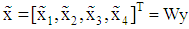 | (2) |
In Minimum mean square error (MMSE) scheme, the MMSE weight matrix is given by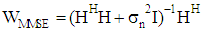 | (3) |
and the detected desired signal from the transmitting antenna is given by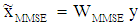 | (4) |
In Zero-Forcing (ZF) scheme, the ZF weight matrix is given by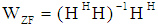 | (5) |
and the detected desired signal from the transmitting antenna is given by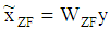 | (6) |
In MMSE-SIC based signal detection scheme, the received signal, channel matrix and noise are extended as 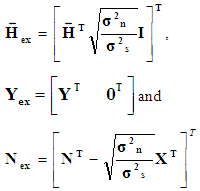 | (7) |
Where,  is the ratio of average receive noise power to average receive signal power. The signal model in terms of transmitted and received signals, noise and channel coefficients can be written as:
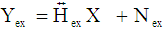 | (8) |
On QR factorization of 8 × 4 sized extended channel matrix,  we get
 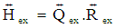 | (9) |
Where,  and
and  represent 8 × 8 sized unitary matrix and 8 × 4 sized upper triangular matrix respectively. Substituting the values of
  in Equation (9) and multiplying with
  , we get
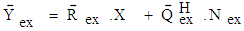 | (10) |
Equation (9) can be rewritten with neglecting  .
.  term as:
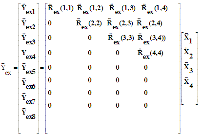 | (11) |
From Equation (11), the primarily estimated detected signal  from the four transmitting antennas can be written as [9, 10]:
 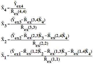 | (12) |
2.1. (3, 2) SPC Channel Coding
In SPC channel coding, the transmitted binary bits are rearranged into very small code words consisting of merely two consecutive bits. In such coding, (3, 2) SPC code is used with addition of a single parity bit to the message u = [u0, u1] so that the elements of the resulting code word x = [x0, x1, x2] are given by x0 = u0, x1 = u1 and x2 = u0  u1 [11]Where, the symbol
  is indicative of the sum over GF (2)
2.2. LDPC Channel Coding
The Gallager code invented as early as 1962 is represented as Low-density parity-check (LDPC) code. In such block code, its parity-check matrix H contains only a few 1’s in comparison to 0’s. The parity-check matrix Hp used in this present study is 64×128 sized. In LDPC channel coding, the input binary data are rearranged into blocks with each block containing 64 binary bits. For each individual block, a 1×128 matrix sized code word c is produced. Its first 64 bits are the parity bits and the last 64 bits are the information bits. In LDPC channel decoding, iterative Log Domain Sum-Product LDPC decoding technique has been implemented to operate alternatively on the bit nodes and the check nodes to find out the most likely code word c that satisfies the condition cHpT= 0[12]. In such decoding scheme, the log-likelihood ratio (LLR) of transmitted code ward c is estimated from received bit sequence rxi converted from (0/1) format into (-1/1) format and passed through AWGN channel of noise variance of N0 as: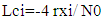 | (13) |
Where, i=1, 2, 3………………….128.The mathematical formulations presented in this section are based on MATLAB source codes available in the website at [13] for iterative Log Domain Sum-Product LDPC decoding algorithm. However, considering all 128 sampled values from Equation (20), a 64×128 sized [LPI] matrix is formed with identical sampled values at its each of 64 rows. In perspective of messages sending sent from bit nodes i to check nodes j, a 64×128 sized [SS] matrix is considered which is formed from the element wise product of two matrices [Hp] and [LPI] as: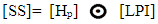 | (14) |
Two useful parameters,  and
and  are estimated from the matrix [SS] using the following relation:
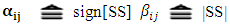 Initially, a 64×128 sized [SSS] matrix is considered as null matrix. In horizontal stepping for finding non zero in the column of Hp matrix, the mmij parameter values at the position (r,l) are estimated using the relation:
 | (15) |
At each position of non-zero element, new values mmij (i,c1) are estimated from the summation of all column wise mmij values previous mmij value at that position where, i=1,2, …….64, c1 is the non-zero elemental position in the column for a row identified by i. With estimated values of mmij (i,c1), mmSum(i,c1) are estimated as: | (16) |
Similarly, another parameter ppp(i,c1) values are estimated from the product of all column wise multiplied  values with
  n value at that position. The previously considered [SSS] matrix is upgraded through inserting the parameter sssji(i,c1) values as:
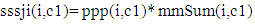 | (17) |
In vertical stepping for finding non zero in the row of Hp party matrix, the Lnij parameter values at the position (r1,j) are updated using the relation: | (18) |
Where, i=1,2………128, j=1,2………128.Finally, a new parameter value is estimated as: 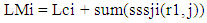 | (19) |
If LMi less than zero, the transmitted bit is 1, otherwise the transmitted bit is 0.
2.3. Convolution Channel Coding and Its Concatenated Form
Convolutional codes are commonly specified by three parameters (n, k, m): n = number of output bits; k = number of input bits; m = number of memory registers. The quantity k/n called the code rate and it is a measure of the efficiency of the code. The constraint length L (=k (m-1)) represents the number of bits in the encoder memory that affect the generation of the n output bits. The presently considered Convolutional Channel Encoder is specified with ½ coding rate, a constraint length of 7 and code generator polynomials of 171 and 133 in octal numbering system. The code generator polynomials G1 and G2 can be written as [14],  | (20) |
 | (21) |
In concatenated channel coding scheme, two convolutional channel encoder are serially connected.
3. System and Signal Models
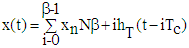
The block diagram of simulated orthogonal multilevel chaos shift keying modulation scheme aided MIMO wireless communication system is depicted in Figure 1. In such simulated system, it has been considered that a segment of audio signal will be processed. The extracted binary signal vector s∈(0,1) from audio signal is channel encoded and interleaved and subsequently processed for coefficient mapping using two consecutive binary bits in two time slots (N=2). In each cases, one of the coefficient values is unity and the remaining are zero. In first time slot (duration of a single bit), a repeated chaotic signal generator outputs directly a chaotic sequence  with the length of the sequence is of β. This sequence is than delayed and repeatedly outputted for one more time, till the end of two consecutive bit duration.The generated chaotic sequence undergoes pulse shaping and can be written under consideration of chip time
  and for a length of time β-1 slot
 | (22) |
In case of considering  as the impulse response of a pulse shaping filter with time duration of Tc, the reference signals in the n-th symbol duration can then be expressed as
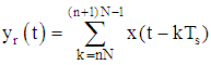 | (23) |
and the data-bearing signal in the n-th symbol duration is computed by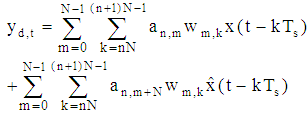 | (24) |
Where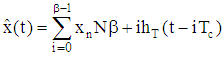 | (25) |
And  is the Hilbert transform of
  and
and  are the four orthogonal Walsh Hadamard codes used for proper identification of individual signal. The reference signal in (23) and the data-bearing signal in (24) are then modulated onto a cosine and a sine carrier, respectively, so that they could be sent via the in phase and quadrature channels.Finally, the transmitted signal in the n-th symbol duration is obtained as
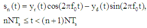 | (26) |
Where  is the frequency of the sinusoidal carriers, such that
  is a multiple of
  . Satisfying
  In an AWGN and Rayleigh fading channel H the received signal is corrupted by a stationary Gaussian noise with zero mean and power spectral density of
  . The received signal can be described by
 | (27) |
The received signal is passed through signal detection technique and fed into spatial multiplexing decoder and to produce a signal channel data vector, 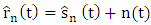 | (28) |
This  signal is multiplied with both in phase and quadrature components of RF signal and filtered with properly designed matched filters. The matched filtered output can be written as;
 | (29) |
 | (30) |
Where  and
and  are two independent Gaussian random variables both with zero mean and variance
  From the signal format in OM-DCSK, it can be easily inferred that and in (29) and (30) as follow;
 | (31) |
 | (32) |
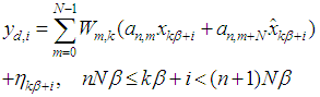
The output of the m-th correlator (Figure 1) is then obtained as: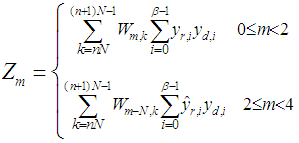 | (33) |
By comparing all the correlator outputs, the coefficient  associated with the largest correlator output will be set to one, while the others are zero.Finally, the data bits can be recovered based on the signals compare and de-mapping. The estimated coefficient values converted into binary form, de-interleaved, channel decoded, binary to integer converted and eventually the transmitted audio signal is retrieved.Orthogonal multi-level chaos shift keying modulation scheme aided MIMO wireless communication system simulation model to be implemented has been discussed thoroughly.The block diagram of such simulated system is depicted in Figure 1.
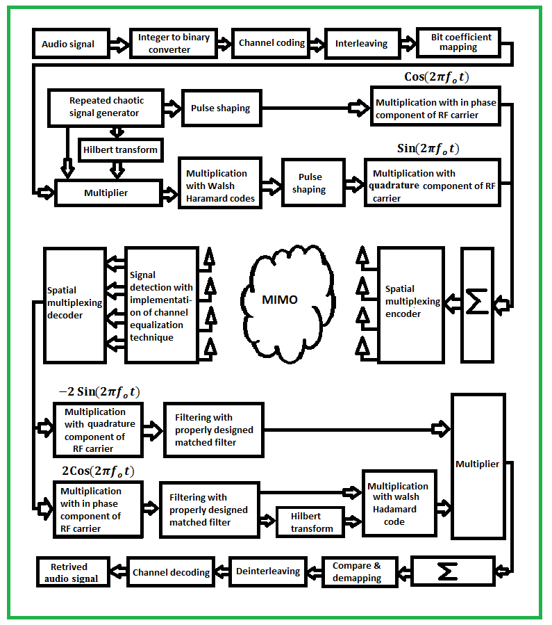 | Figure 1. Block diagram of Orthogonal Multi-Level Chaos Shift keying modulation scheme aided MIMO wireless communication system |
4. Result and Discussion
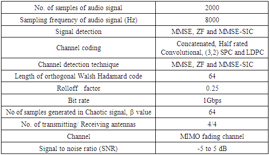
In the section, we have presented the simulation results showing the impact of the various channel coding and signal detection techniques on performance evaluation of Orthogonal Multi-level Chaos Shift Keying Modulation Scheme aided MIMO Wireless Communication System. The system performance has been shown in term of BER using MATLAB Ra2017a based on the simulation parameters presented in table 1.Table 1. Summary of the Simulated Model Parameters
 |
| |
|
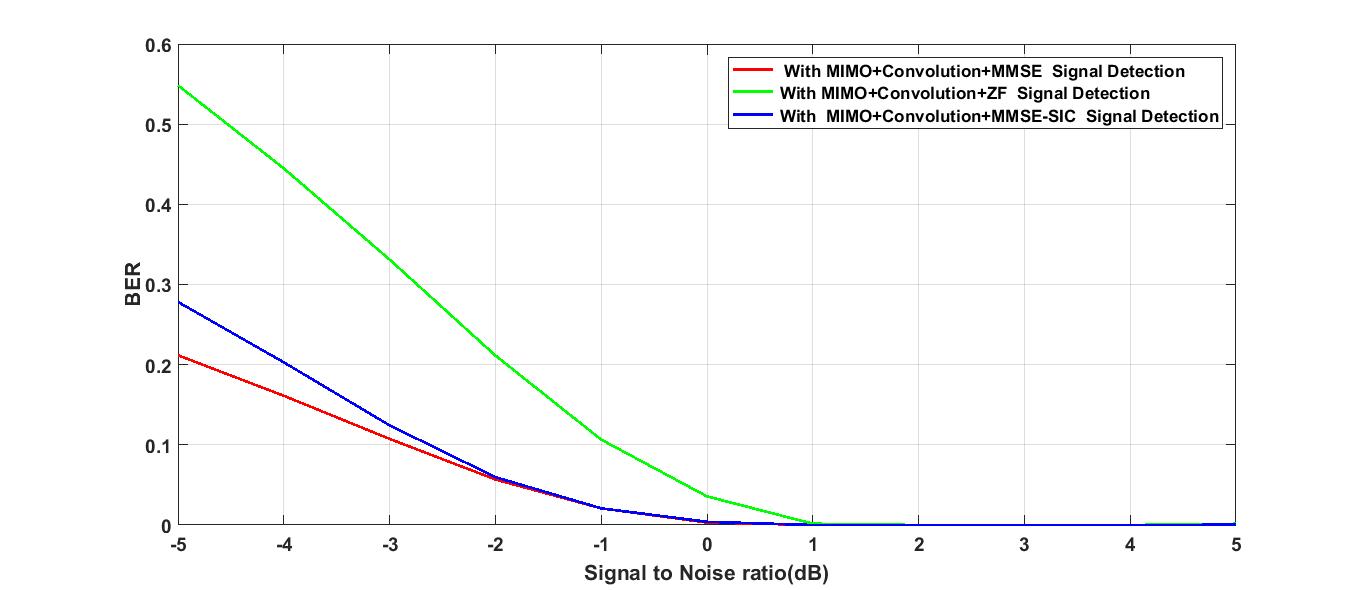
Form the graphical illustration presented in Figure 2 through Figure 5 it is keenly observable that the simulation system shows comparatively better performance under implementation of MMSE signal detection technique.In Figure 2, the system performance under scenario of various signal detection and concatenated channel coding in very much well defined. For a typically assumed a SNR value of -4 dB, the estimated BER values are 0.0554, 0.1014 and 0.2779 in case of MMSE, ZF and MMSE-SIC signal detection technique which is indicative of system performance improvement of 2.625 dB and 7.003 dB in case of MMSE relative to ZF and MMSE-SIC signal detection technique respectively. At 5% BER a SNR gain of 0.65 dB is achieved in MMSE as compared to ZF and 2.70 dB in MMSE as compared to MMSE-SIC.Under identical consideration of SNR value, it is noticeable from Figure 3, For a typically assumed a SNR value of -4 dB that the estimated BER values are 0.1612, 0.4448 and 0.2029 in case of MMSE, MMSE-SIC, ZF signal detection technique respectively. In such case system performance improvement 4.4079 dB and 0.9917 dB are achieved in MMSE as compared to MMSE-SIC and ZF signal detection techniques. At 10% BER SNR gain of 0.30 dB and 1.90 dB are obtained in MMSE as compared to MMSE-SIC and ZF signal detection technique.In Figure 4, it is observable that the system performance in case of MMSE and MMSE-SIC signal detection technique is not we discriminated from each other over a significant SNR reason. For a typically assumed SNR value of -4 dB, the estimated BER values are 0.2249 and 0.2794 in case of MMSE and ZF signal detection techniques which ratifies a system performance improvement of 0.9424 dB. At 10% BER SNR gain of 0.70 is obtained in MMSE as compared to ZF.In Figure 5, it is seen that the system performance in case of MMSE signal detection technique is improving linearly at low SNR value region with increase in SNR value. For a typically assumed SNR value of -4 dB 0.1192 and 0.2669 in case of MMSE and ZF which is indicative a system performance 3.9633 dB.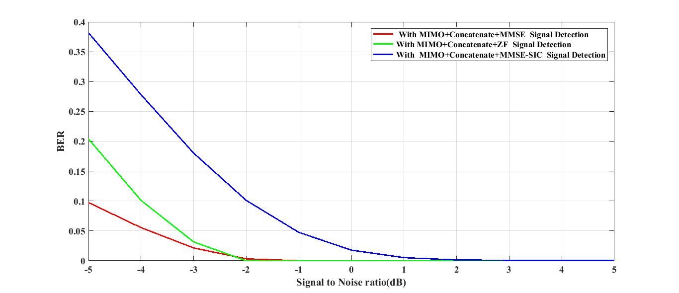 | Figure 2. BER performance of Multi-level chaos shift keying modulation scheme aided wireless communication system in concatenate channel using MMSE, ZF and MMSE-SIC signal detection technique |
 | Figure 3. BER performance of Multi-level chaos shift keying modulation scheme aided wireless communication system in Convolution channel using MMSE, ZF and MMSE-SIC signal detection technique |
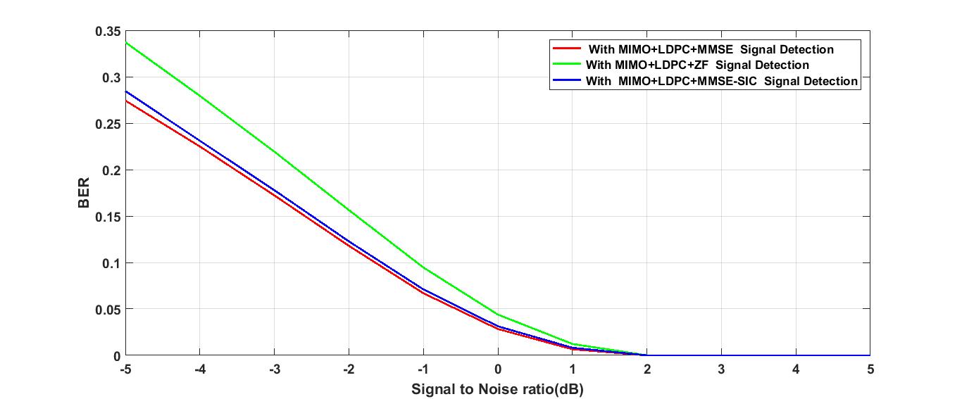 | Figure 4. BER performance of Multi-level chaos shift keying modulation scheme aided wireless communication system in LDPC channel using MMSE, ZF and MMSE-SIC signal detection technique |
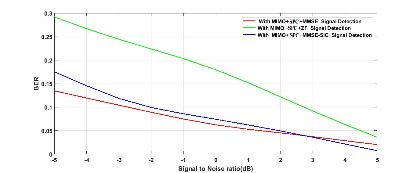 | Figure 5. BER performance of Multi-level chaos shift keying modulation scheme aided wireless communication system in (3, 2) SPC channel using MMSE, ZF and MMSE-SIC signal detection technique |
5. Conclusions
In this paper, the performance of orthogonal multi-level chaos shift keying modulation scheme aided MIMO wireless communication system has been investigated on audio signal transmission using various channel coding and signal detection techniques. It is found from the simulation based study that our presently considered simulated system is very much robust in retrieving data at very low SNR value regime under implementation of concatenated convolutional channel coding scheme with proper utilization of MMSE signal detection technique. It can be concluded that orthogonal multi-level chaos shift keying modulation scheme using concatenated convolutional channel coding and MMSE signal detection techniques can be effectively considered in future generation 5G/6G and IOT applications.
References
| [1] | Xiangyun Zhou, Lingyang Song and Yan Zhang, Physical layer security in wireless communications, 1st ed. CRC Press, Taylor and Francis Group, 2013. |
| [2] | Naoto Horiike, Eiji Okamoto and Tetsuya Yamamoto, 2017, Performance Improvement of chaos MIMO scheme by LDPC code concatenation using symbol MAP detection and STBC, in Proceeding of IEEE International Conference on Information Networking (ICOIN), 200-205. |
| [3] | Tingting Huang, Lin Wang, Weikai Xu and Francis C.M. Lau, 2016, Multilevel code-shifted differential-chaos shift-keying system, IET Communications, 10, 1189 – 1195. |
| [4] | Weikai Xu, Tingting Huang, Lin Wang, 2017, Code-Shifted differential chaos shift keying with code index modulation for High Data Rate Transmission, IEEE Transactions on Communications, 65, 4285-4294. |
| [5] | Hua Yang, Wallace K. S. Tang, Guanrong Chen, and Guo-Ping Jiang, 2017, Multi-Carrier chaos shift keying: System Design and Performance Analysis, IEEE Transactions on Circuits and Systems–I, 64, 2182-2194. |
| [6] | BAI Chao, REN Hai-Peng, LI Jie, 2016, A Differential chaos-shift keying scheme based on hybrid system for underwater acoustic communication, Proceeding of IEEE/OES Ocean Acoustics symposium, Harbin, China, 1-5. |
| [7] | Georges Kaddoum Ha-Vu Tran, Long Kong and Micheal Atallah, 2017, Design of simultaneous wireless information and power transfer scheme for short reference DCSK communication systems, IEEE Transactions on Communications, 65 (1), 431-443. |
| [8] | Hua Yang, Wallace K. S. Tang, Guanrong Chen, Guo-Ping Jiang, 2016, System design and performance analysis of orthogonal multi-level differential chaos shift keying modulation scheme, IEEE Transactions on Circuits and systems 63 (1), 145-146. |
| [9] | Yong Soo Cho, Jackson Kim, Won Young Yang, Chung G. Kang, MIMO-OFDM wireless communications with MATLAB, John Wiley and Sons (Asia) PTE Limited, Singapore, 2010. |
| [10] | Lin Bai, Jinho Choi, Low Complexity MIMO Detection, Springer Science and Business Media, LLC, New York, USA, 2012. |
| [11] | Giorgio M. Vitetta, Desmond P. Taylor, Giulio Colavolpe, Fabrizio Pancaldi and Philippa A. Martin, Wireless Communications Algorithmic Techniques, John Wiley and Sons Ltd, United Kingdom, 2013. |
| [12] | Yuan Jiang, A practical guide to error-control coding using MATLAB, Artech House, Norwood, MA, USA, 2010. |
| [13] | Bagawan Sewu Nugroho, https://sites.google.com/site/bsnugroho/ldpc. |
| [14] | Sneha Bawane, V.V.Gohokar, 2014, Imulation of convolutional encoder, International Journal of Research in Engineering and Technology (IJRET), India, 3 (3), 557-561. |

 Abstract
 Reference
 Full-Text PDF
 Full-text HTML