-
Paper Information
- Paper Submission
-
Journal Information
- About This Journal
- Editorial Board
- Current Issue
- Archive
- Author Guidelines
- Contact Us
International Journal of Networks and Communications
p-ISSN: 2168-4936 e-ISSN: 2168-4944
2018; 8(1): 1-9
doi:10.5923/j.ijnc.20180801.01

An Efficient Chaotic Interleaving with Convolution Encoder and Decoder for Simplicity in LTE System
 Abstract
 Reference
 Full-Text PDF
 Full-text HTML
M. E. Abd Elhameed1, M. A. M. El-Bendary2, E. O. Begheet3, H. M. Abd Elkader3
1Worker University, Egypt
2Department of Communication Technology, Faculty of Industrial Education, Helwan University, Egypt
3Department of Electonics and Communication, Faculty of Engineering, Banha University, Egypt
Copyright © 2018 Scientific & Academic Publishing. All Rights Reserved.
This work is licensed under the Creative Commons Attribution International License (CC BY).
http://creativecommons.org/licenses/by/4.0/

In this paper an efficient technique presents for reducing the computational complexity of the turbo coding in LTE (Long Term Evolution) system. It proposed the chaotic interleaving algorithm for the convolution codes. The presented interleaving is based on chaotic Baker map applied with (2,1,3) convolution codes and (2,1,7) convolution codes compared with turbo coding used in LTE system. The transmitted data will respect to transmit with shorter constrain length of the encoder and the chaotic interleaving enhances the security with the different secret key for every transmitted packet. The proposed system achieves the simplicity, decreases the time delay and saves power compared to the existing system.
Keywords: Convolution code, Chaotic, Zigzag and block Interleaving Mechanism, Mobility, Simplicity
Cite this paper: M. E. Abd Elhameed, M. A. M. El-Bendary, E. O. Begheet, H. M. Abd Elkader, An Efficient Chaotic Interleaving with Convolution Encoder and Decoder for Simplicity in LTE System, International Journal of Networks and Communications, Vol. 8 No. 1, 2018, pp. 1-9. doi: 10.5923/j.ijnc.20180801.01.
Article Outline
1. Introduction
- Wireless communication is a rapidly growing technology. The beginning of mobile communication technologies goes back to the first analog mobile radio systems, which are labeled as the first generation (1G). The second generation (2G) introduced the first digital mobile systems, while the third generation (3G) presented the first mobile systems handling broadband data transfer Long Term Evolution (LTE) “release 8.0” is often called the fourth generation (4G) but many claim that LTE “release 10.0”, also known as LTE-Advanced, is the true 4G evolution step, while LTE “release 8.0” is referred to as 3.9G [1]. The Third Generation Partnership Project (3GPP) set up its own set of technical requirements for LTE and LTE-Advanced that includes the incorporation of many of the latest wireless communication technologies such as: Orthogonal Frequency Division multiple Access (OFDMA), Multiple Input Multiple Output (MIMO), dynamic resource allocation, channel width flexibility and mobility management [2]. The evolution into the 4G systems is driven by many factors such as: the development of new services for mobile devices and the increasing demand for higher data rates and lower latency for many interactive services. LTE with its latest technologies promises a set of advantages for future mobile communication systems such as: increased data rates, support of high mobility, scalable channel bandwidths, improved spectral efficiency, throughput and access efficiency and lower latency.In this paper, we investigate a critical part of the LTE-based receivers that contributes significantly in achieving the LTE requirements for an acceptable overall performance this part is the coding part have a major impact on the whole system performance. Where trades off between complexity and BER have to be considered. Part of the system design requires identifying low-complexity while maintaining a satisfactory Bit Error Rate (BER) performance.A turbo code is the used code in LTE system which is consist of two constituent encoders and an interleaving which is very complicated it means increasing in hard ware implementation, high power consumption, delay in time. Where there are applications don’t need a high BER. so, we design code system consist of conventional code with a proposed interleaving m and compare between them by MATLAB simulation and by vertex 6 FPGA program and we can see the save in hard ware, time power, by another word save in cost.
2. LTE Coding Scheme
- The coding scheme presented in 3GPP LTE specification is a classic turbo coding scheme, including two constituent encoders and one interleaving module. It is described in Fig.1. One can observe at the input of the LTE turbo encoder the data block Ck. The K bits corresponding to this block are sent as systematic bits at the output in the steam Xk. In the same time, the data block is processed by the first constituent encoder resulting parity bits Zk, while the interleaved data block C’k is processed by the second constituent encoder resulting parity bits Z’k. Combining the systematic bits and the two streams of parity bits, the following sequence is obtained at the output of the encoder: X1, Z1, Z’1, X2, Z2, Z’2, …, Xk, Zk, Z’k. At the end of the coding process, in order to drive back the constituent encoders to the initial state, the switches from Fig. 1 are moved from position A to B. Since the final states of the two constituent encoders are different, depending on the input data block, this switching procedure will generate tail bits for each encoder. These tail bits have to be transmitted together with the systematic and parity bits resulting the following final sequence: Xk+1, Zk+1, Xk+2, Zk+2, Xk+3, Zk+3, X’k+1, Z’k+1, X’k+2, Z’k+2, X’k+3, Z’k+3.
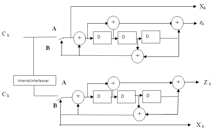 | Figure 1. Structure of the LTE Turbo encoder |
 | (1) |
 | (2) |
3. Interleaving Mechanisms
- Error correction codes are usually used to protect signals through transmission over wireless channels. Most of the error correction codes are designed to correct random channel errors. However, channel errors caused by mobile wireless channels are bursts in nature. Interleaving is a process to rearrange the samples of the transmitted signal so as to spread bursts of errors over multiple code words. The simplest and most popular of such interleaving mechanisms is the block interleaving. Firstly, the basics of block interleaving [4] are reviewed. Then, the proposed chaotic interleaving mechanism and the zigzag interleaving mechanism are presented in the next subsections.
3.1. The Block Interleaving Mechanism
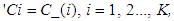
- The idea of block interleaving can be explained with the aid of Fig. 2 block interleaving is applied to the signal samples. The samples are first arranged to a matrix in a row-by-row manner and then read from this matrix in a column-by-column manner. Now, take a look at how the block interleaving mechanism can correct error bursts. Assume a burst of errors affecting four consecutive samples (1-D error burst) as shown in Fig. 2 (b) with shades. After de-interleaving, the error burst is effectively spread among four different rows, resulting in a small effect for the 1-D error burst as shown in Fig. 2 (c). With a single error correction capability, it is obvious that no decoding error will result from the presence of such 1-D error burst. This simple example demonstrates the effectiveness of the block interleaving mechanism in combating 1-D bursts of errors [10, 11].Let us examine the performance of the block interleaving mechanism when a 2-D (2 × 2) error burst occurs [5], as shown in Fig. 2 (b) with shades. Fig. 2 (c) indicates that this 2 × 2 error burst has not been spread, effectively, so that there are adjacent samples in error in the first and the second rows. As a result, this error burst cannot be corrected using a single error correction mechanism. That is, the block interleaving mechanism cannot combat the 2 × 2 bursts of errors.
 | Figure 2. Block interleaving of an 8 × 8 matrix |
3.2. The Proposed Chaotic Interleaving Mechanism
- As mentioned in the previous subsection, block interleaving is not efficient with 2-D bursts of errors. As a result, there is a need for advanced interleaving for this task. The 2-D Chaotic Baker map in its discretized version is a good candidate. The chaotic randomization step generates permuted sequences with lower correlation between their samples such that a reduction in the PAPR can be achieved. Also, the chaotic Baker map distributes the errors in a better way to samples after de-interleaving [12, 13]. Moreover, the chaotic Baker map adds a degree of encryption to the transmitted signal.The OFDM signals have large PAPR due to high correlation between their data frames. If this long correlation pattern of the in-phase and the in-quadrature components are broken down, a reduction in the PAPR can be achieved. Interleaving can be used to break these correlation patterns. The chaotic Baker map is used for the randomization of both components.The discretized Baker map is a good candidate to randomize the items in a square matrix. It can be described by B (n1, n2……, nk), where the vector, [n1, …, nk], represents the secret key, Skey. Defining M as the number of data items in one row, the secret key is chosen such that each integer mi divides M, and m1 + … + mk = M.Let Mi = m1 + … + mi. The data item at the indices (r,s), is moved to the indices [3, 12, 13]:
 | (3) |
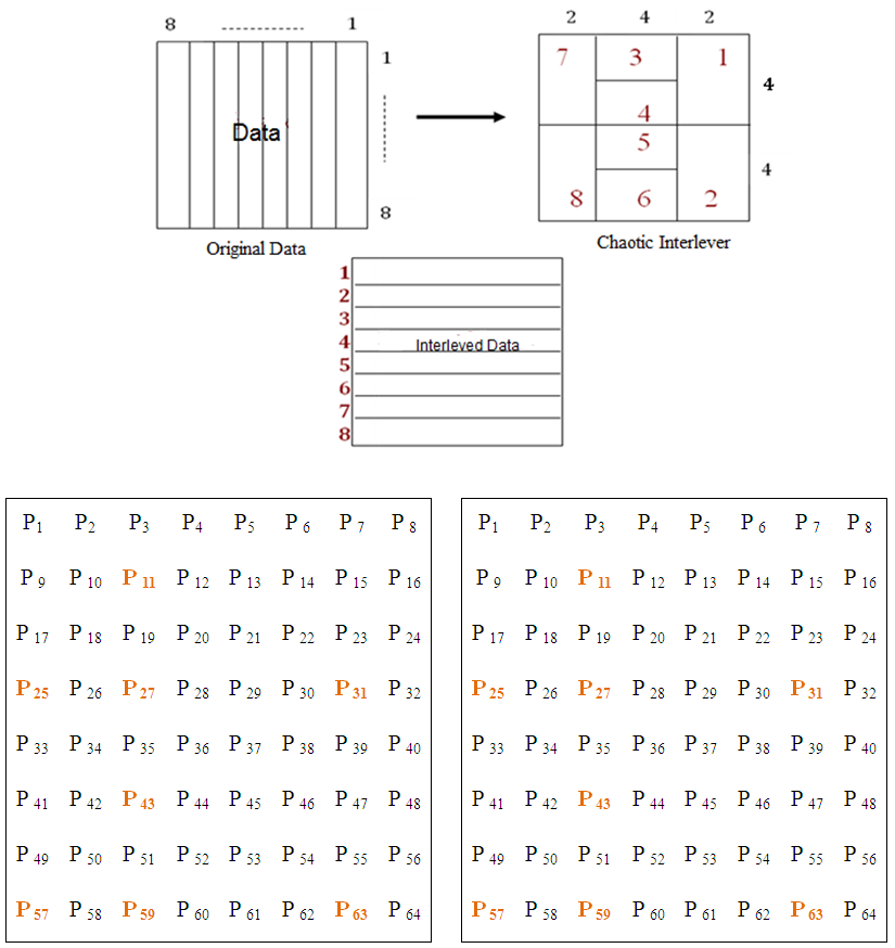 | Figure 3. 2-D chaotic encryption of an 8 8 matrix and its operation mechanism |
3.3. The Proposed Zig Zag Interleaving Mechanism
- Zigzag interleaving as proposed in is attractive for high data rate applications due to their low encoding and decoding complexity and their excellent performance particularly with high code rate [14]. The data bits DI, j ∈ {0,1} are arranged in an I ×J matrix. Each row of the matrix is called a segment of the zigzag interleave. The parity bits pi is determined as the modulo 2 sums over each segment i including the previous parity bit pi−1. The zigzag interleaving is completely described by the two parameters I and J. Low complexity decoding can be is using a forward and backward recursion. We examine the performance of the Zig Zag interleaving mechanism when a 2-D (2 × 2) error burst occurs, as shown in Fig. 4 (b) with shades. Fig. 4 (c) indicates that this 2 × 2 error burst has been spread. As a result, this error burst can be corrected to some extent using a single error correction mechanism. That is, the Zigzag interleaving mechanism can combat the 2 × 2 bursts of errors, approaching the two interleaving mechanisms mentioned before in addition to their low encoding and decoding complexity.
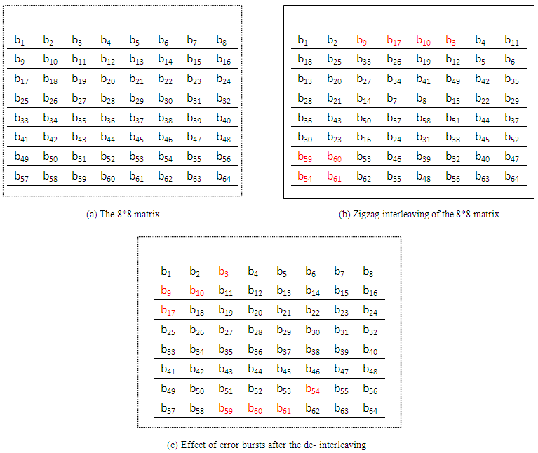 | Figure 4. Zig Zag Interleaving of 8 × 8 Matrix |
4. Proposed Modifications
- The proposed system is based on building the LTE system but with replacement the coding block from turbo encoder to (2,1,3) convolution codes and (2,1,7) convolution codes and test them with our model. We use different types of modulation with our designed system and find that the QPSK (Quadrature phase shift keying) modulation is the best one. We also compare between two types of equalizers the MMSE equalizer and the ZF (zero forcing) equalizer and we found that the ZF equalizer is the suitable for our model testing it on AWGN and Rayleigh Channel as we can be seen in Fig. 5.
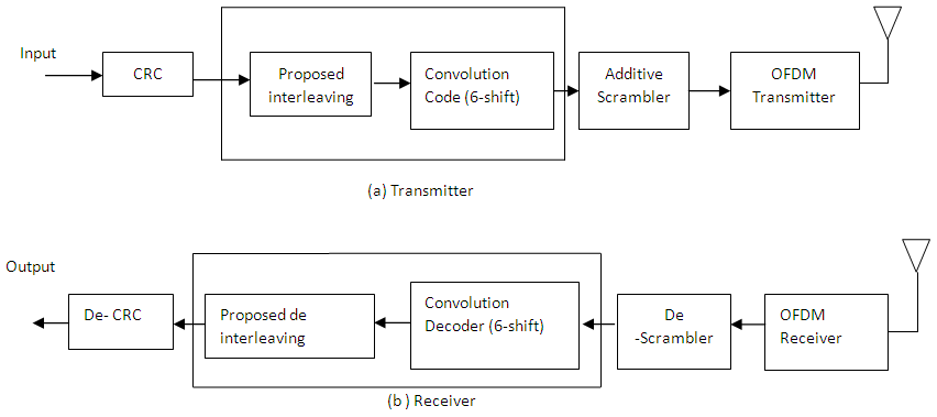 | Figure 5. The proposed model of LTE system |
5. Simulation Results
- First we examine the LTE proposed model with (2,1,7) convolution and with (2,1,3) convolution codes compared with the turbo code we find that the turbo code is the best in BER reductions as shown in Fig. 6. The convolution code achieves the simplicity with BER suitable for carrying sound and image. The transmission of sound or image doesn’t require the complication of turbo code while the proposed model saves hardware structure, time and power resulting in saving in cost. We compared between them by the use of vertex 6 FPGA. Encoder & decoder with chaotic interleaving and deinterleaving because the turbo code depend on algorithms and problem solving so it consume a logic gates which is not used In our system and we found the delay time in turbo code at clock cycle 50 nsec. 203.5µsec in the other side in our design system the delay time at clock cycle 50nsec is 18 µsec and we found our system con work until clock cycle 20nsec and the delay time will be 7.29 µsec then the delay time in turbo is increase about 28 time from our system.
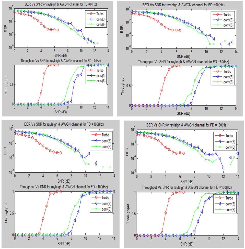 | Figure 6. BER and throughput via SNR[dB] for a Rayleigh & AWGN channel with different FD |
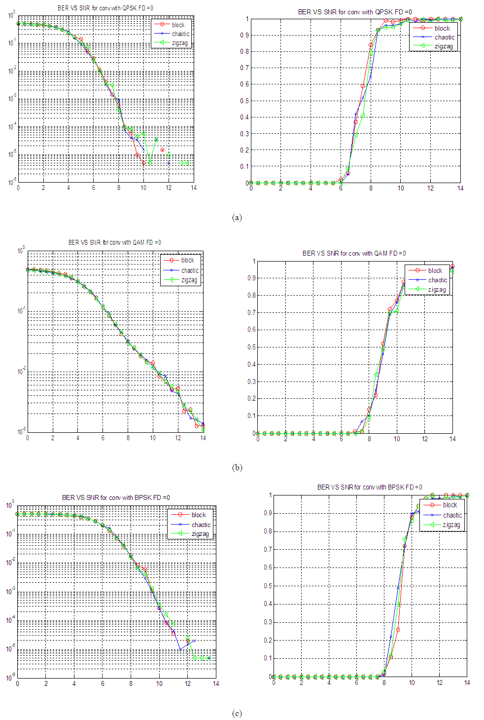 | Figure 7. Throughput and BER of LTE system with proposed interleavings and convoluational code (2,1,7) on AWGN and Rayleigh Channel for adaptive modulation techniques (a) QPSK, (b) QAM and (c) PPSK |
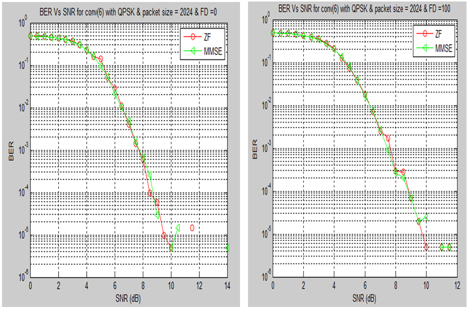 | Figure 8. BER via SNR[dB] in convolution code (1,2,7) with chaotic interleaving with using ZF & MMSE equalizers |
6. Conclusions
- This paper presented a simple and efficient novel chaotic interleaving and zigzag interleaving for the transmission of data over LTE system. A comparison study between the proposed interleaving and the turbo coding techniques used in LTE system has been presented. The computer simulation results have revealed the effectiveness of the proposed interleaving at simplicity and saving in hard ware implementation and have a BER accepted in a lot of application. Also, the proposed interleaving enhanced the security level as it is based on chaotic map.