Charles U. Ndujiuba, Oluwafemi A. Ilesanmi, Oboyerulu E. Agboje
Electrical and Information Engineering Department, Covenant University, Ota, Nigeria
Correspondence to: Charles U. Ndujiuba, Electrical and Information Engineering Department, Covenant University, Ota, Nigeria.
| Email: |  |
Copyright © 2017 Scientific & Academic Publishing. All Rights Reserved.
This work is licensed under the Creative Commons Attribution International License (CC BY).
http://creativecommons.org/licenses/by/4.0/

Abstract
In this paper, variation of the antenna parameters with the dimensions of an edge cut of an inset fed rectangular patch antenna with a partial ground was studied. Antenna parameters like the gain return loss and VSWR. Regular rectangular patch antenna with the ground plane reduced to half and symmetrically position around the feed point was designed and simulated using HFSS software. The partial ground was kept constant while the shape of the radiating patch was modified using different edge cut geometry. This was designed at an operating frequency of 3GHz, with FR4 of dielectric constant 4.4 as substrate. The result obtained shows that antenna parameters show noticeable improvement when the width of the edge cut is more than the length of the edge cut.
Keywords:
Edge-cut, Partial ground, Inset-fed, Patch Antenna, Microstrip
Cite this paper: Charles U. Ndujiuba, Oluwafemi A. Ilesanmi, Oboyerulu E. Agboje, Effect of Edge-cut Dimensions on the Electrical Parameters of an Inset-fed Rectangular Microstrip Patch Antenna with Partial Ground, International Journal of Networks and Communications, Vol. 7 No. 2, 2017, pp. 40-46. doi: 10.5923/j.ijnc.20170702.02.
1. Introduction
The concept of microstrip radiators was first put forward by Deschamps in 1953, but was never practically realized until in the 1970s, when researchers like Robert E. Munson and the rest took further steps to develop it using low-loss soft substrate materials that were just becoming available. Microstrip antennas are planar resonant cavities that radiate as a result of fringing fields around it edges attaining peak efficiency when its impedance is matched [1].Microstrip patch antennas are the most versatile and commonest form of etched antennas. They have a lot of advantages when compared with other types of conventional antennas and hence have wide area of applications like mobile and satellite communication, global positioning system and radar application to mention a few.The simplest form of microstrip patch antenna is made up of a dielectric substrate sandwiched between a metallic radiating patch at one end and a ground plane at the other end with a feeding point. The radiating patch is made of a conducting material which can be copper or gold and can be fed using any of the different feeding techniques. Patch antennas come in different shapes like: rectangular, square, circular, elliptical and triangle and their sizes depend on the thickness of the substrate. The most popular of these are the rectangular and the circular patch antennas and both have a wide radiation patterns.However, other shapes like those based on fractal genetic have been used in the design of microstrip patches [8]. According to [8], E shaped fractal patch antenna was designed for multiband application to cover the S band of the LTE, though using multilayered substrate which will definitely increase the size of the antenna. The need for multiband miniaturized antennas for our present day wireless application has given rise to various methods of designing microstrip patch antennas. One of these methods is by using fractal geometry. The fractal self-similarity characteristic can be used for multiband resonator application [9]. One of the most popular fractal geometry in use is the Gasket Sierpinski. According to [10], a Gasket Sierpinski has a base shape of an equilateral triangle and various heights of the triangle were used to achieve various frequency bands. Stacked sierpinski has also been used to further improve the multiband feature of a patch antenna.The larger the size of the ground plane, the better the performance of the patch antenna [2]. But using a large ground plane will make the antenna unsuitable for portable and mobile applications. This is the reason for the reduction in the size of the ground plane and is made up for by cutting the edge of the radiating patch. In this paper, edge cut of an inset fed conventional microstrip patch with partial ground is investigated using HFSS.
2. Design and Methodology
The following equations are used to determine the dimensions of a conventional rectangular patch antenna, following the steps:Determining the width of the patch: the width W is calculated using [5-7].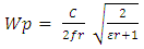 | (1) |
Where, c is the speed of light in free space = (3x10⁸m/s)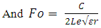 | (2) |
Le being the effective length of the patch and is given as  | (3) |
Next is to calculate the effective dielectric constant: 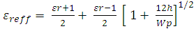 | (4) |
Where εr is the dielectric constant of the substrate and  is the effective dielectric constantNext is to calculate the effective length, which is given as
 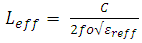 | (5) |
Next step is to determine the extended length of the patch due to the fringing field and it’s given as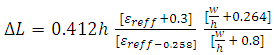 | (6) |
The real length of the patch is given as: 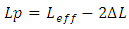 | (7) |
To determine the ground plane dimensions length (Lg) and width (Wg)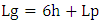 | (8) |
 | (9) |
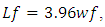
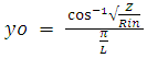
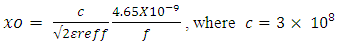
Feed point Location of an Inset Fed Rectangular Patch (xo, yo, wf, Lf).There are different methods of feeding a patch antenna like: probe feed, microstrip line feed, aperture coupled feed and proximity coupling feed. But of all, microstrip line feed and the coaxial probe feed are commonly used because of their simplicity.Microstrip inset feed method was used in this design for proper input impedance matching and the line parameters were designed using a standard input impedance of 50Ω [2]. Feed point location where input impedance is approximately 50Ω can be calculated using [3, 4]. | (10) |
Where,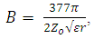 | (11) |
 | (12) |
 | (13) |
 | (14) |
Using equations 1-14, relevant antenna dimensions were calculated. Thereafter the dimension of the ground plane was reduced to half and the edges of the radiating patch modified. This was designed using different edge cut dimensions and simulated to investigate its effect on the electrical characteristics of the antenna. The table below shows the various geometry of the edge cut combined with a constant partial ground and the result obtained from the simulation using Ansoft HFSS software.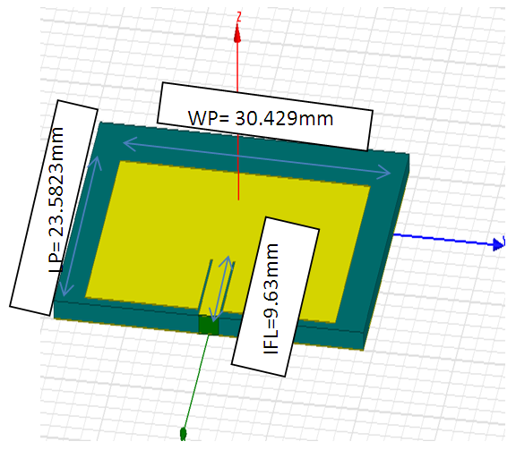 | Figure 1. Full radiating Patch |
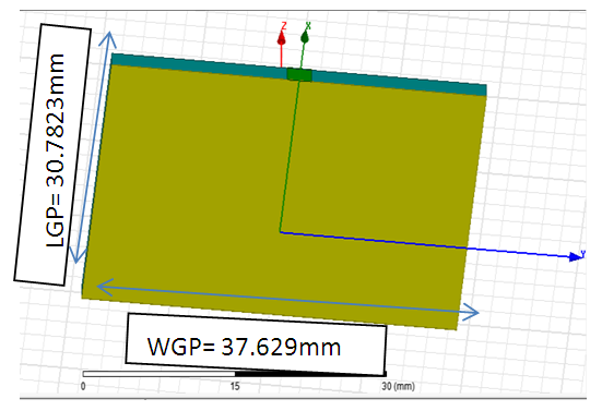 | Figure 2. Full ground Plane |
WP –Width of Radiating Patch, LP- Length of radiating Patch, IFL- Inset feed length, WGP- Width of Ground Plane, LGP – Length of Ground Plane, WPG – width of partial ground, LPG – Length of partial ground, EGW – Edge cut width, ECL – Edge cut Length Modified patch antenna.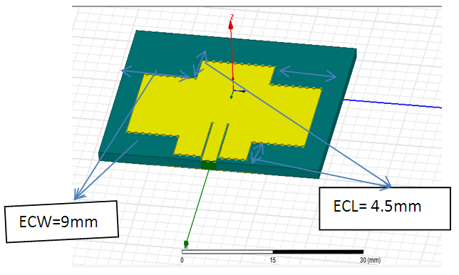 | Figure 3. Edge Cut (L= 4. 5mm, W = 9mm) |
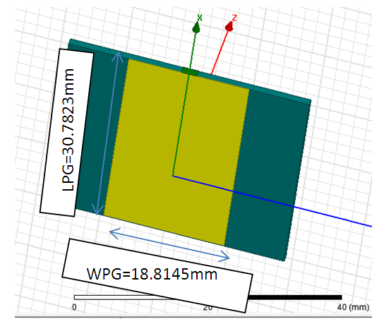 | Figure 4. Partial Ground |
3. Result and Analysis
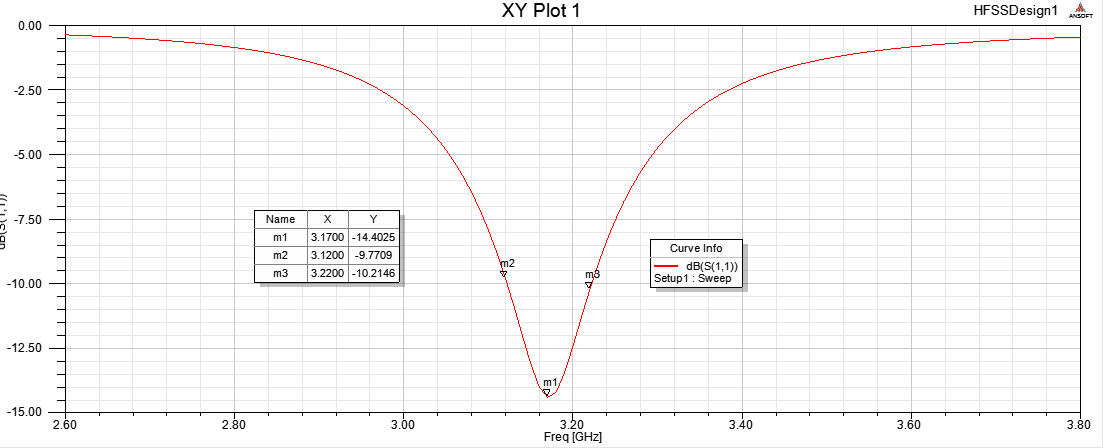
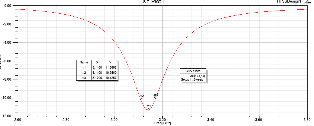
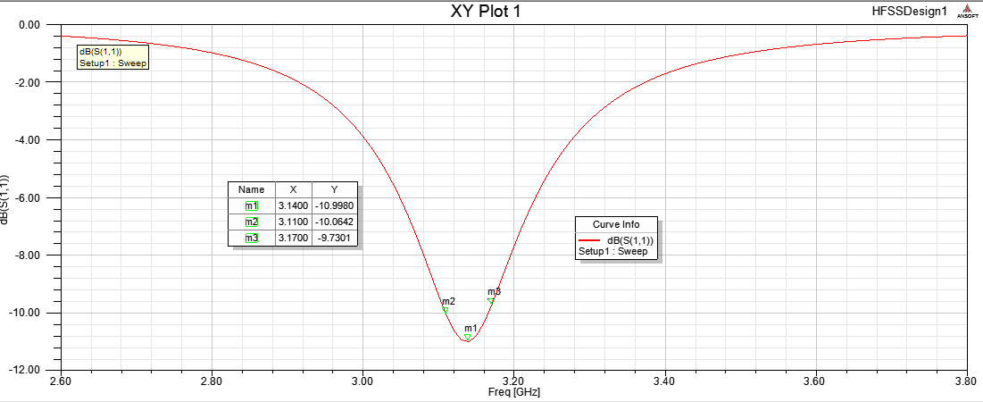 | Figure 5. Return loss for full radiating patch with partial ground |
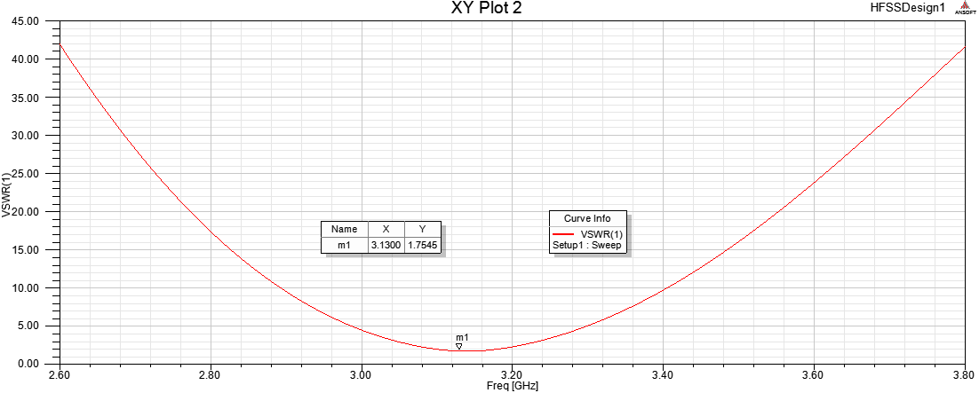
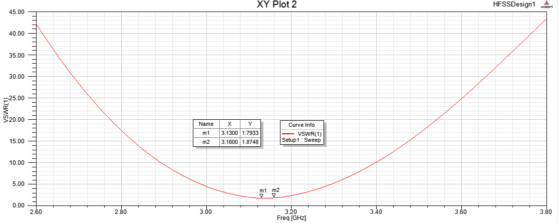 | Figure 6. VSWR for full radiating Patch with Partial Ground |
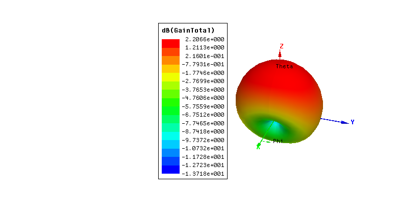
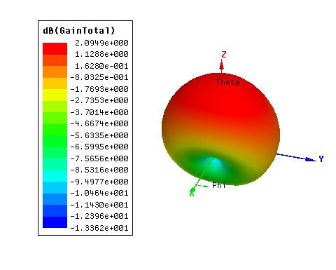
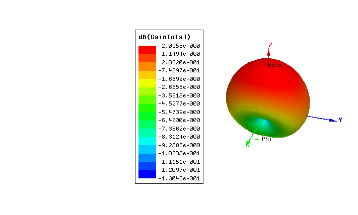 | Figure 7. Gain Plot for full radiating Patch with Partial Ground |
 | Figure 8. 1x7 Return loss |
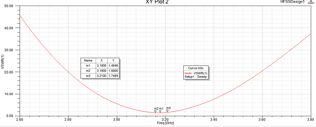 | Figure 9. 1x7 VSWR |
 | Figure 10. 1x7 Gain plot |
 | Figure 11. 7x1 return loss |
 | Figure 12. 7x1 VSWR |
 | Figure 13. 7x1 Gain |
The table below shows the summary of all the results obtained from the simulations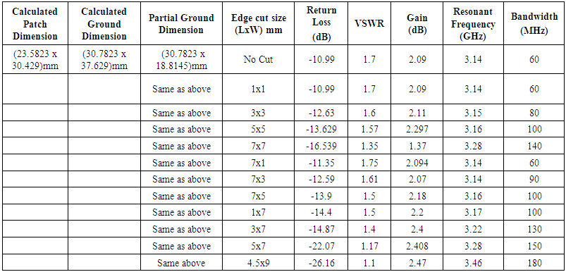 | Table 1. Variation of the antenna parameters with the radiating patch edge cut dimensions |
From the table shown above, it can be seen that the antenna parameters showed almost the same responses when the length and the width of the edge cut were the same and when the length was kept higher than the width.But when the width of the edge cut was kept higher than the length, a sharp improvement was noticed in the antenna response.
4. Conclusions
Reducing the dimension of the ground plane in a way affects the performance of a patch antenna but reduces the overall size of the antenna. The effect of this can be overcome by cutting the edges of the radiating patch.From the simulation result and the table shown, it is clear that by using partial ground with edge cut of patch. Better performance can be achieved from the patch antenna when the width of the edge cut is more than its length.
References
| [1] | Milligan, Thomas A. Modern Antenna Design. s.l.: Wiley-IEEE Press, 2005. |
| [2] | Nita Kalambe, Dhruv Thakur, Shubhankar Paul , Design of Microstrip Patch Antenna for Wireless Communication Devices., International Journal of Science and Research, 2015. |
| [3] | Choudhury, Suvadeep, Effect of Dielectric permittivity and height on a Microstrip Fed Rectangular patch antenna, Interntional journal of Electronics & communication Technology, 2014, pp. 1-2. |
| [4] | M.A Martins, A.I. Sayeed, A design rule for Inset fed Rectangular Microstrip Patch Antenna., WSEAS Transactions on Communications, 2010. |
| [5] | Hussain, Hind S, Inverted E-shape Microstrip Antenna for Bandwidth and Gain Enhancement.. Journal of Wireless Networking and Communication, Vol. 6 No. 2, 2016, pp. 47-55. |
| [6] | Suhana Rashid, Chandan Kumar Chakrabarty, Bandwidth Enhanced Rectangular Patch Antenna Using Partial Ground Plane Method For WLAN Applications.: Universiti Tenaga Nasional, Putrajaya Campus. 2015. The 3rd National Graduate Conference. |
| [7] | Charles U. Ndujiuba, Adebiyi A. Adelakun, Oboyerulu E. Agboje, Hybrid Method of Analysis for Aperture-Coupled Patch Antenna Array for MIMO Systems, International Journal of Electromagnetics and Applications 2015, 5(2): 90-97 DOI: 10.5923/j.ijea.20150502.03. |
| [8] | Puente J Anguera, C. Borja, J Solaer, Fractal –shaped antenna and their application to GSM 900/1800, Journal of the institution of British Telecommunication Engineers, Vol2, Part 3, July-Sept, 2001. |
| [9] | A Janani, A. Ptiya, Design of E- shaped fractal simple multiband patch antenna for S- Band LTE and various mobile Standards. |
| [10] | Mayank Jain, Prof. (Dr.) R.P Agarwal, Design and Fabrication of Sierpinski fractal antenna for multiband wireless Application, International journal of Engineering Research and Management, Vol3, Issue 12, 2016. |

 Abstract
 Reference
 Full-Text PDF
 Full-text HTML