Motaz Daadoo, Yousef-Awwad Daraghmi
Department of Computer Systems Engineering, Palestine Technical University - Kadoorie (PTUK), Tulkarm, Palestine
Correspondence to: Motaz Daadoo, Department of Computer Systems Engineering, Palestine Technical University - Kadoorie (PTUK), Tulkarm, Palestine.
| Email: |  |
Copyright © 2017 Scientific & Academic Publishing. All Rights Reserved.
This work is licensed under the Creative Commons Attribution International License (CC BY).
http://creativecommons.org/licenses/by/4.0/

Abstract
This paper focuses on an application of wireless sensor networks for leakage detection in underground water pipes to overcome the problem of water dispersion in water distribution networks. Leakage prevention and breaks identification in water distribution networks are fundamental for an adequate use of natural resources. To address this problem, and simplify the leakage identification process, the authors have designed a wireless network system making use of mobile wireless sensors able to detect breaks and save energy, time and cost with having Smart Water Leakage Detection (SWLD) in pipelines, measure water level in tank and control in pump to turn it on when water level is low. It focuses mainly on two parts: The first part is alarm based on Global System for Mobile technology (GSM) to send Short Message Service (SMS) to the owner. The system is made up of basic components: sensors, GSM module, Arduino, relays to control the device. The second is the controlling part; it uses Android application mobile to control the pump. The result of using the proposed system is improving the efficiency of operation, reducing delay time and cost of maintenance pipelines after leakage detection.
Keywords:
Arduino, GSM, SMS, Smart Water Leakage Detection (SWLD), Wireless Sensor Networks (WSN)
Cite this paper: Motaz Daadoo, Yousef-Awwad Daraghmi, Smart Water Leakage Detection Using Wireless Sensor Networks (SWLD), International Journal of Networks and Communications, Vol. 7 No. 1, 2017, pp. 1-16. doi: 10.5923/j.ijnc.20170701.01.
1. Introduction
Water is a limited resource and is essential for agriculture, industry and for creatures existence on earth including human beings. Lots of people don’t realize the real importance of drinking enough water every day. More water is wasted by many uncontrolled way. This problem is quietly related to poor water allocation, inefficient use, and lack of adequate and integrated water management. Therefore, efficient use and water monitoring are potential constraint for home or office water management system. Every living thing on earth needs water to survive. Human bodies are made up of more than 60 % water. We use clean water to drink, grow crops for food, operate factories, and for swimming, surfing, fishing and sailing. Water is vitally important to every aspect of our lives. Monitoring the quality of surface water will help protect our waterways from pollution. Farmers can use the information to help better manage their land and crops [1]. Our local, state and national governments use monitoring information to help control pollution, water leakage and losses levels. Water monitoring day was established in 2003 by America’s clean water foundation as a global educational outreach program that aims to build public awareness and involvement in protecting water resources around the world. World water monitoring day is celebrated on September 18.The main reason for leakage of the distribution water pipelines is the pressure on the pipelines when exceeds the maximum pressure rated by manufacturer when these pipelines designed. So, it will cause a deformation on the pipes and this will lead the pipes to explode during the water flowing through them [2]. After this occurs and the pipes explode, the water will leave its main track and will leave pipes and leakage will occurred [3].In this paper we will show the whole system ideas, procedure, benefits, devices and apparatus used to accomplish the whole system in technical way with high efficiency. The main idea talks about how to detect the leakage which occurs in water distribution pipelines and the decrease in water level in tank so, this problems causes many difficulties for home and its owners.By using water monitoring system SWLD, we avoid the water wastage, power consumption and easily prevent the water for our generation. If our idea applied in fully technical true way, this will be very useful for domestic environment. This experimental system will save money for owners and will detect the leakage in water distribution pipelines and helps the owner to be familiar with the problems early to make the required maintenance. In our system we make a home model to be a prototype for SWLD system. We arrange water pipelines and put water sensors on points which have high probability for water leakage. A microcontroller also required (Arduino) to control and process the actuators on its output ports, also to receive data from water sensors. The Arduino connect to GSM to detect the water leakage and decreasing in water level rapidly and remotely and then send SMS to the owner. And we use the Android application to receive these data from GSM and control on pump. The goal of this system is to design and manage a Wireless Sensor Networks (WSN) that helps to monitor the location of water leakage with the help of information sensed by the sensors located above water hoses, so as to keep the water resource within a standard described for domestic usage and to be able to take necessary actions to restore the health of the degraded water quantity. We use Arduino mega2560 microcontroller to design and build a water leakage detection & wireless control system which provides the user with new features such as water leakage detection and water level control in tank by mobile application. The purpose of the system is to bring comfort and energy saving to our lives.
2. GSM Technology
The wireless voice services started by the first generation circuit switched analogue service, which was for voice only; this technology did not provide SMS or other data services. Upgrading from first generation to Second digital system Generation (2G); this transition was posted due to several services provided by 2G technologies such as: data storing, coping, encryption and compression, and permits data transmission without loss be supporting error correction. The Second generation technologies 2G, includes GSM that is based on both Time Division Multiple Access mechanism (TDMA), and Frequency Division Multiple Access mechanism (FDMA), where a spectrum is divided into small slices, as well each slice is divided in time to multiple time slices, where users are allocated in turn to specific spectrum slice, and specific time slice as well [4]. Moving from 2G to 2.5G technologies, GSM/GPRS (General Packet Radio Services) that is a data-oriented technology extending the GSM voice services where GPRS theoretical can provide up to 200Kbps; which made an introduction to another revolutionary change [5].The Third Generation cellular networks (3G) were developed with the aim of offering high speed data and up to 2 Mbps in the served areas or more which allow the operators to offer a multimedia connectivity and other data services to the end customers. A few technologies are able to fulfill the mentioned data rate such as Code Division Multiple Access (CDMA), Universal Mobile Telecommunications System (UMTS) and others. High Speed Packet data Access (HSPA) has been an upgrade to Wideband Code Division Multiple Access (WCDMA) networks used to increase packet data performance. The required downloads and data volume demand has been recently increased per user. The High Speed downlink Packet Access (HSDPA) is developed to provide more data rates and up to 14.4Mbps to meet the users demand. HSDPA using different telecommunication techniques to increase the down-link data flow by developing different modulation and using Multiple-Input and Multiple-Output (MIMO) technology. Moreover, the upgrading to the Fourth Generation system 4G means that more data demand going to be booming during the coming decades, the fourth generation which called Long Term Evolution (LTE) is developed to meet the rapidly data demand [6, 7].The 4th generation still not utilizing major part in the market share due to the lack of devises that can support the LTE Orthogonal Frequency-Division Multiple Access (OFDMA) technique and the existing network infrastructure required [8]. Nowadays, the LTE still supporting the data services only and not the voice, but it is in the process and development to support the voice also, after that, it will be called as “advanced LTE”. The LTE can support more than 100 Mbps depends on the network structure and spectrum used [9]. This paper mainly focuses on providing security when the user is away from home. SMS is a GSM mobile technology that can perform remote communication wherever they are. The aim of paper is to use Arduino microcontroller to design and build a water leakage detection & wireless control system, that give us send fast information to user GSM mobile device using SMS and also activate - deactivate system by SMS, which provides the user with new features such as water leakage detection and water level control in tank by mobile application. The result of using the proposed system is improving the efficiency of operation, reducing delay time and cost of maintenance pipelines after leakage detection.
3. Proposed System
In this paper we produce a system for detecting the water leakage and control water pump which is related to a domestic use and needs, so we apply this system on a model of a simple home to show and explain how this system can be applicable to be built in of any civil structure. The main purpose of this paper is to describe the structure that we built for our system. We use a home model to build the plumbing network in, also to provide this network with the control parts and the sensors that we used to detect the water leakage and the water level in the upper tank. Also the water supply distribution pipes and collector will be shown in the following Figure 1 which describe and show the architecture design structure model that we use. The Figure 1 shows the main parts of the control board, the microcontroller (Arduino), water pump (actuator) and the GSM and their connections.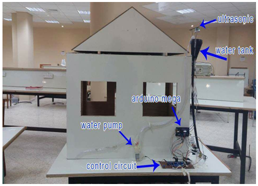 | Figure 1. Model of SWLD system |
All actuators which are solenoid valve and the water pump are activating by a DC voltage with fixed value of 12 volt. A water pump is used to supply the water tank when the water level decreased, this will be happened when the owner of the home use the Android mobile application to turn on the pump depending on the alarm notification alarm of the water level in the upper tank.
4. Methodology
Based on the design requirements and specifications, the system block diagrams shown in Figure 2 and Figure 3 are developed. This block diagram defines all the function to be performed by the system. A modular approach to system design was taken. The system is designed based on an Adriano mega2560 microcontroller which based on ATmega2560 microprocessor. In this paper, some of the basic concepts of circuits that are used in the system design are explained.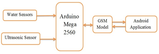 | Figure 2. System block diagram |
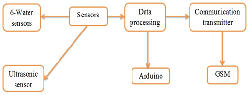 | Figure 3. Functional block diagram of the SWLD |
The system contains water sensors to detect leakage and ultrasonic sensor to measure water level in tank. The sensors collect information and the system is controlled by the mega Arduino, the controller decides the risk and sends SMS to the owner using a GSM module, according to the sensors information. The system also consists of two parts: the first is the alarm, if there is one of the risk the system sends SMS using GSM; it also decreases the risk by opening the water solenoid valves in case of leakage. The second part is controlling using Android application. The application controls the pump and turns on if there is low water level in tank.Tank water level monitoring, is used to avoid overflowing and under flowing level of water in the tank. Water controlling system implementation makes potential significance in home applications. The existing automated method of level detection is described and that can be used to make a device on/off. Moreover, the common method of level control for home appliance is simply to start the feed pump at a low level and allow it to run until a higher water level is reached in the water tank. This is not properly supported for adequate controlling system. Besides this, liquid level control systems are widely used for monitoring of liquid levels, reservoirs, silos, and dams etc. Based on the design requirements and specifications, the first main function of this system is to detect water leakage which occurs in the distribution units and tracks of the domestic plumping network, this will be experimentally true and result an acceptable results that will be using water leakage sensors which will be classified in the hardware components specification. These sensors will be fixed and located mechanically in true way on the distribution water hoses above the hoses and around the elbows that used to change the direction of the flowing water hoses, the mechanical distribution shown in Figure 4.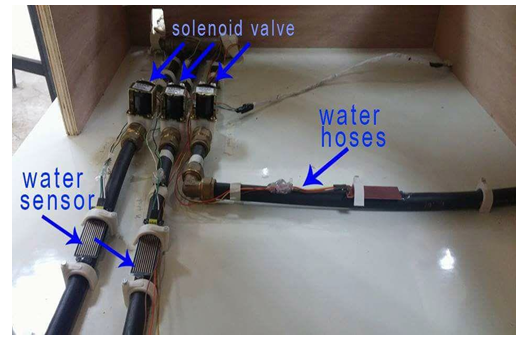 | Figure 4. Water leakage sensors and their mechanical distribution |
Water leakage sensors distributed mechanically with a sequence related to the solenoid valves. In other meaning, when one of the water leakage sensors detect the leakage and send a signal to the controller, the solenoid valve which is related and supply the water track which this sensor located on, this valve will close and stop water flow through it.The second main function of this system idea is to detect and measure the water level of the upper domestic tank which is usually located on the roof, we use an ultrasonic sensor to measure the water height in the tank, depending on the comparison between the actual value of water level and the preselected value, an actuator which is water pump will be turned on to supply the upper tank. This actuation of the pump will be wireless control feature using an Android application to control the activation of the pump. As shown in Figure 1 the pump connected to the upper tank and the ultrasonic located above the upper level of the water tank.The next Figure 5 shows the main functions of our system which deals mainly with water leakage and the controlled pump far away using the mobile and GSM technology, we can use this figure to explain theoretically what happened actually to the system depending on the controller and the control features from the user of the Android application. Also, all parameters which are used in the system are shown in the figure and how these parameters are related together.
5. Hardware Design
We’ve mentioned the hardware components as shown in Figure 2, in this paper we will go through the system hardware setup step by step in details for combining the components with each other to establish the desired tools and making the connection between the hardware parts with the software commands to get automation sensing unit and actuators. Hardware part of the system nearly was simple and easy to understand and deal with, it contains the controller which is Arduino mega category #2560, water leakage sensors, solenoid valves, ultrasonic sensor, water pump, electrical relays to control the activation of the valves and the pump depending on the input data from sensors and we use ULN 2003 to connect the output pins of the controller with the electrical relays. The following sections describe all hardware components and its specifications and classifications.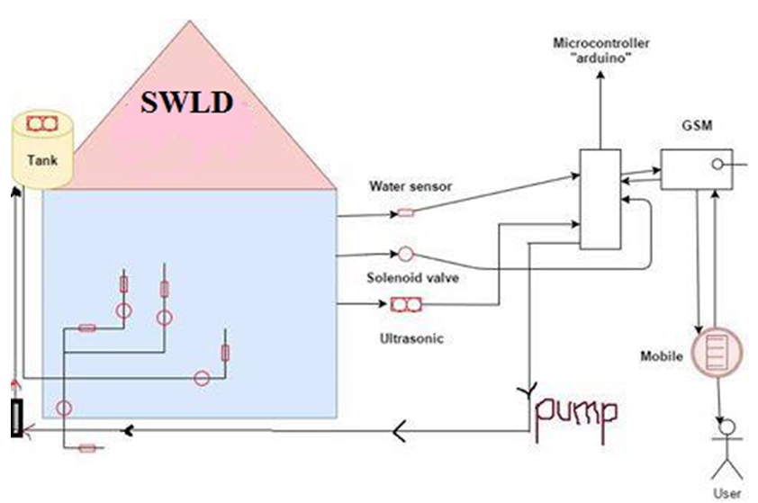 | Figure 5. General purpose scheme of SWLD system |
5.1. Arduino MEGA 2560 Microcontroller
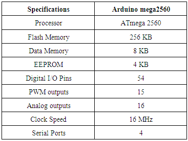
This paper is using an Arduino mega2560 (Figure 6), which is based on an ATmega2560 microprocessor. An Arduino mega2560 microcontroller has been designed based on an ATmega2560 microprocessor that runs at the speed of 16MHz. As Table 1 shows, it contains 54 digital input/output pins, 15 of them could be used as Pulse Width Modulation (PWM) which is a method for getting analog results with digital means outputs. Furthermore, it contains 16 analog inputs and 4 hardware serial ports.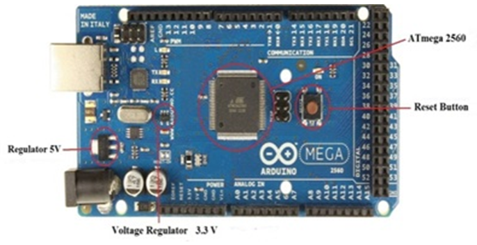 | Figure 6. Arduino mega2560 |
Table 1. Specifications of Arduino mega2560 microprocessor
 |
| |
|
5.2. GSM Module Unit
The GSM modem unit is built using SIMCOM SIM900 modem that specialized for Arduino controller and support GPS technology as shown in Figure 7. This unit can send SMS to user mobile phone and also can receive SMS from user.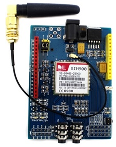 | Figure 7. SIM900 for Arduino controller |
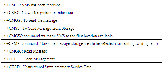
The working of GSM modem is based on commands, the commands always start with AT (which means ATtention) and finish with a character. The AT commands are given to the GSM modem with the help of PC or controller. The GSM modem is serially interfaced with the controller with the help of MAX232. Here MAX232 acts as driver which converts TTL levels to the RS-232 levels. For serial interface GSM modem requires the signal based on RS-232 levels. The T1_OUT and R1_IN pin of MAX232 is connected to the TX and RX pin of GSM modem. The AT commands for GSM-GPRS support is as follows in Table 2:Table 2. AT commands for GSM-GPRS
 |
| |
|
Since many GSM network operators have roaming agreements with foreign operators, users can often continue to use their mobile phones when they travel to other countries. SIM cards (Subscriber Identity Module) holding home network access configurations may be switched to those will metered local access, significantly reducing roaming costs while experiencing no reductions in service.To connect the GSM 900 with Arduino mega we will do the connections as follows:Ÿ RX of GSM ------------> TX of ArduinoŸ TX of GSM -------------> RX of ArduinoŸ GND of GSM ------------> GND of Arduino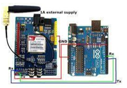 | Figure 8. Connect the GSM 900 with Arduino mega |
5.3. Water Sensor
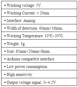
Water sensor brick is designed for water detection, which can be widely used in sensing the rainfall, water level, even the liquate leakage. The brick is mainly comprised of three parts: an electronic brick connector, a 1 MΩ resistor, and several lines of bare conducting wires.This sensor works by having a series of exposed traces connected to ground and interlaced between the grounded traces are the sense traces. The sensor traces have a weak pull-up resistor of 1 MΩ. The resistor will pull the sensor trace value high until a drop of water shorts the sensor trace to the grounded trace. Believe it or not this circuit will work with the digital I/O pins of your Arduino or you can use it with the analog pins to detect the amount of water induced contact between the grounded and sensor traces.This item can judge the water level through with a series of exposed parallel wires stitch to measure the water droplet/water size. The item can easily change the water size to analog signal, and output analog value can directly be used in the program function, then to achieve the function of water level alarm. The item has low power consumption, and high sensitivity, which are the biggest characteristics of this module. The item can be compatible with Arduino UNO, Arduino mega2560, Arduino ADK etc.The following figures shows the physical representation of water sensor and connecting diagram of water sensor, Table 3 shows the specification of water sensor.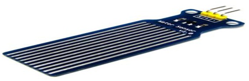 | Figure 9. Physical representation of water sensor |
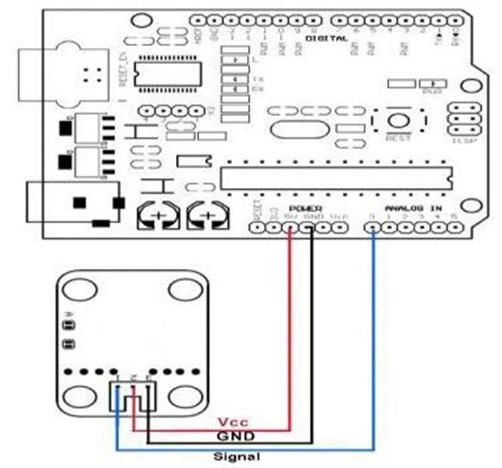 | Figure 10. Connecting diagram of water sensor |
Table 3. Specification of water sensor
 |
| |
|
5.4. Ultrasonic Sensor
In this system we deal with ultrasonic sensor, which main function is to measure simultaneously the level of water in the domestic water tank, depending on the result of the ultrasonic level sensor, we can control in the electrical pump by using the Android application.The following Figure 11 shows the physical representation of ultrasonic sensor, Table 4 shows the specification of ultrasonic sensor.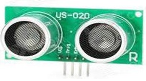 | Figure 11. Physical representation of ultrasonic sensor |
Table 4. Specification of ultrasonic sensor
 |
| |
|
5.5. ULN2003
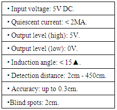
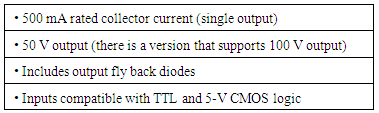
The ULN2003A is an array of seven NPN Darlington transistors capable of 500mA, 50V output. It features common-cathode fly back diodes for switching inductive loads. It can come in PDIP, SOIC, SOP or TSSOP packaging. In the same family are ULN2002A, ULN2004A, as well as ULQ2003A and ULQ2004A, designed for different logic input levels.The UNL2003A is also similar to the ULN2001A (4 inputs) and the ULN2801A, ULN2802A, ULN2803A, ULN2804A and ULN2805A, only differing in logic input levels (TTL, CMOS, PMOS) and number of inputs.The ULN2003 is known for its high-current, high-voltage capacity. The drivers can be paralleled for even higher current output. Even further, stacking one chip on top of another, both electrically and physically, has been done. Generally it can also be used for interfacing with a stepper motor, where the motor requires high ratings which cannot be provided by other interfacing devices.The following Figure 12 shows the structure and pins classification of ULN2003A, Table 5 shows the specification of ULN2003A. | Figure 12. ULN2003 structure and pins classifications |
Table 5. ULN2003A specifications
 |
| |
|
5.6. Water Pump
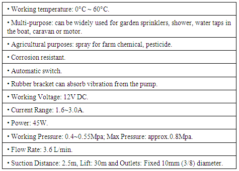
High pressure micro diaphragm water pump, automatic switch 3.6L/min, DC 12V, 45W, this is a high quality DC micro diaphragm pump, widely used in general industry equipment, farming, tour vehicles, special vehicle, ship, beverage, vehicle cleaning, carpet cleaning, ground cleaning, water purification and water treatment equipment [3].The following figures show the components of the water pump and control circuit of the water pump, Table 6 shows the specification of water pump.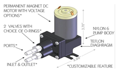 | Figure 13. Components of the water pump |
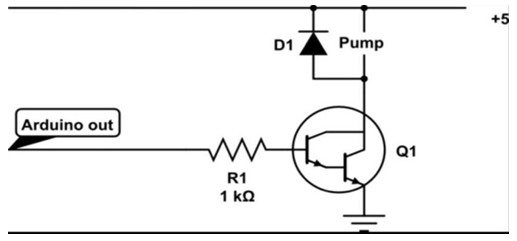 | Figure 14. Control circuit of the water pump |
Table 6. Water pump features
 |
| |
|
5.7. Solenoid Valve
A solenoid in Figure 15 is a simple electromagnetic device that converts electrical energy directly into linear mechanical motion, but it has a very short stroke (length of movement), which limits its applications.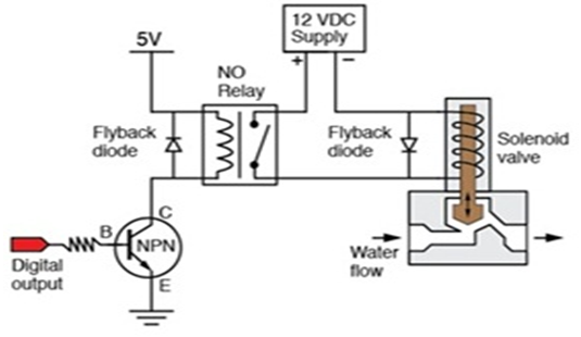 | Figure 15. Equivalent circuit for solenoid valve |
5.8. Relay 12v
As Figure 16 relay is an electrical switch that opens and closes under the control of another electrical circuit. In the original form, the switch is operated by an electromagnet to open or close one or many sets of contacts.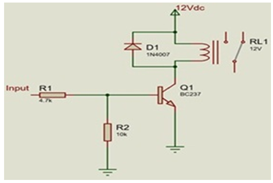 | Figure 16. Equivalent circuit for relay |
6. Driving Circuitry
We have designed and developed a driving circuit given in the Figure 17 in order to operate SWLD system. The driving circuitry is developed using an Arduino mega 2560 microcontroller. It controls and runs specific functions which will simulate the main structure we use to show and employ the components of our system and how each particle will be.In this driving circuit, we distribute the sensors on the input pins as shown and we connect their electrical supply and ground. Also we substitute the solenoid valves and the water pump which are unavailable on the simulation program to DC motors on the output actuators of the system.Using protous simulation program we got the following driving circuit.
7. Software Design and Implementation
In this paper we describe the software system design, program techniques, and system approaches used in the development of programming the microprocessor in the SWLD system. The software program is responsible for accepting data and commands, executing different commands, controlling operational terminals, and supporting data Input/output ports. This paper discusses the software in terms of routines and subroutines. The software mainly consists of two parts, one is control part, and the other is alarm part. It is intended to give a general idea of program flow and implementation.
7.1. Arduino
In this system Arduino software from Arduino developer is used to develop program for Arduino controller. ArduinoIDE is an integrated development environment (IDE) used in computer programming. It contains a base workspace and an extensible plug-in system for customizing the environment. ArduinoIDE is written mostly in Java, but it may also be used to develop applications in other programming languages through the use of plug-in, including: Ada, ABAP, C, C++, etc., the environment is written in C++ and based on processing and other open-source software. This software can be used with any ARDUINO board.
7.2. Android Application Development
This is an open source Android application which has a graphical interface. An Android application is a software application that runs on the Android platform. An Android application is designed for a smartphone or a tablet running on the Android OS. Android application is written in Java programming language and use Java core libraries. Users can extend its abilities by installing plug-in written for the eclipse platform, such as development toolkits for other programming languages, and can write and contribute their own plug-in modules.For our system software, we have many functions which are performed by the system’s circuit like acquire sensor data, process the input data, communicate with the module to send and receive data, convert the data to output, send output signal to output modules. For our system the Android mobile application must allows users to control all the system by sending a message to Arduino over the network, and then commands will be issued by the microcontroller towards relays. The Android mobile application could operate seven alarm parts (six water sensors and the seventh is ultrasonic sensor) and one control part on/off pump.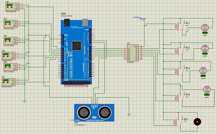 | Figure 17. Circuit diagram |
7.3. Alarm Part
The system consists of two parts: the first is the alarm, if there is one of the risk the system sends SMS using GSM; it also decreases the risk by opening the water solenoid valves in case of leakage.
7.3.1. Water Sensor
Flowchart for water sensor, shown in Figure 18, when the water leaking happen, water sensor detect this risk and send the reading to Ardiuno, Arduino alarm the user that there is a leakage in his/her home.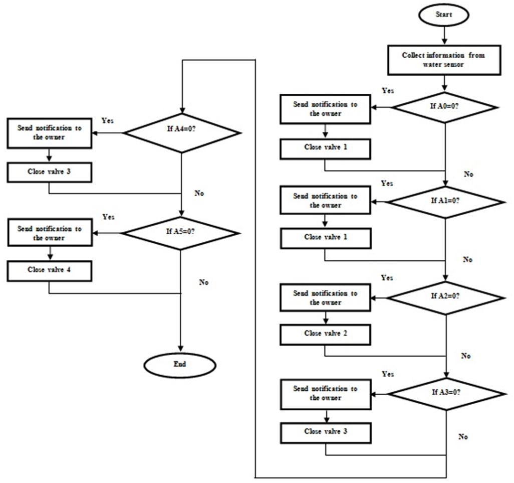 | Figure 18. Flowchart for water sensor |
7.3.2. Ultrasonic Sensor
Flowchart for ultrasonic sensor, shown in Figure 19, when the water level decrease in the tank, ultrasonic sensor detects this decreasing and sends the reading to Ardiuno, Arduino alarm the user that there is a decreasing in the tank.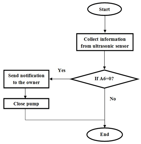 | Figure 19. Flowchart for ultrasonic sensor |
7.4. Control Part
The second part is controlling using Android application. The application controls the pump and turns on if there is low water level in tank.
7.4.1. Pump
First the pump is off when the homeowner wants to turn it on he must enter the correct username and password, as shown in Figure 20, then the main facade which contains three main parts: notifications, send instruction and about us, when user choose send instruction he will see two sub parts: on and off, then he choose to on the pump, when he do this the message is sent to the Arduino which controls all the system, Arduino sends a message to the pump then the pump on. The Figure 21 shows a flowchart for opening/closing pump. 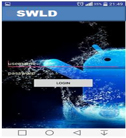 | Figure 20. Interface for enter username and password |
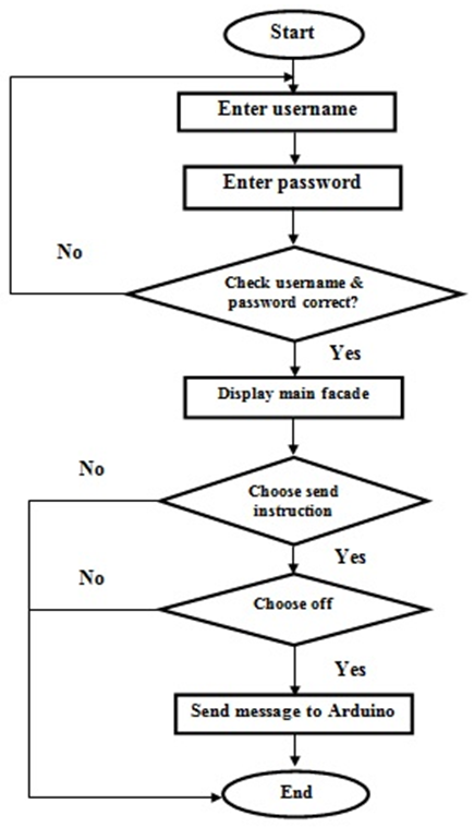 | Figure 21. Flowchart for pump |
7.5. Flowchart of Android Application
For our system the Android mobile application must allows users to control all the system by sending a message to Arduino over the network, and then commands will be issued by the microcontroller towards relays. The Android mobile application could operate seven alarm parts (six water sensors and the seventh is ultrasonic sensor) and one control part on/off pump, Flowchart for Android application, shown in Figure 22.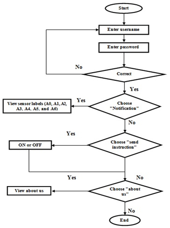 | Figure 22. Flowchart for Android |
7.6. Flowchart of the Total System
Figure 23 shows the flowchart of the total system, which is also clearly showing how to turn on or turn off pump and valves by sending SMS from user mobile phone. The system will check the water sensors, and the water level sensor (ultrasonic). If there a leakage or decreasing in water level at the tank, the system will take necessary action to inform the house owner. In case any risk is there, the device gives alarm to the owner by sending SMS to owner. In control part, owner receives SMS from device in his/her home then the owner can control pump by turn it on/off.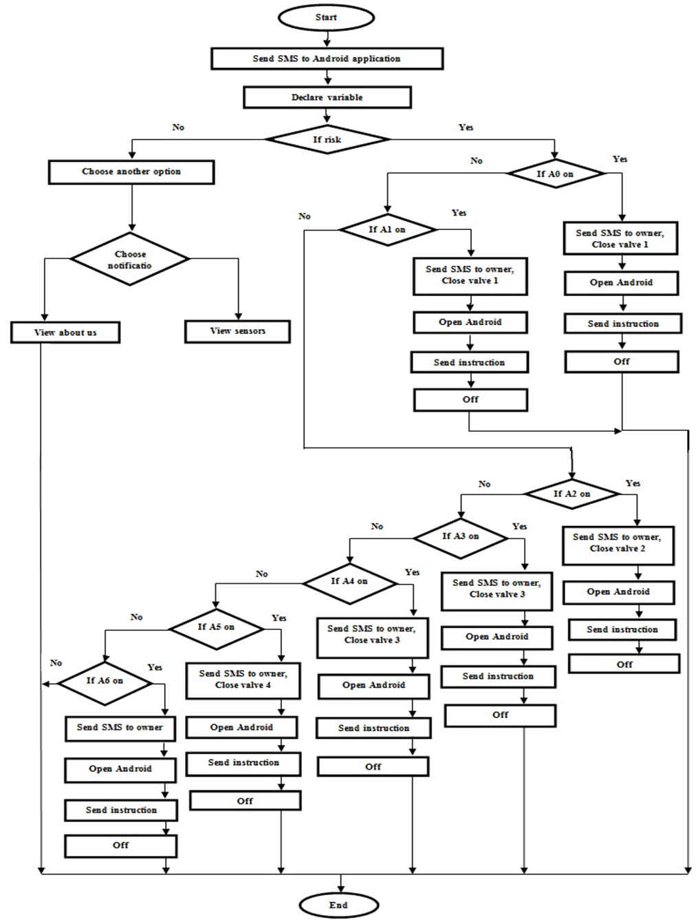 | Figure 23. Flowchart of the total system |
7.7. UML Diagrams
7.7.1. Use Case Diagram
Figure 24 shows home owner must be login at first, he/she can choose any of the choice which appear in main display of application (notification, send instruction and about us), when he/she choose the first choice it include seven part (A0, A1, A2, A3, A4, A5, A6) and our system do two thing detect risk and send SMS.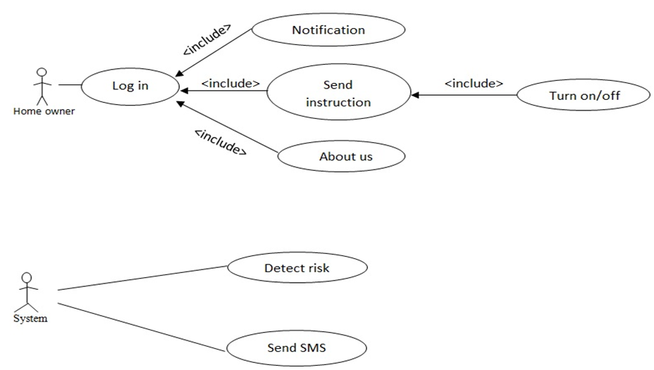 | Figure 24. Use case diagram |
7.7.2. Activity Diagram
Figure 25 shows activity diagrams for our system. At first, sensor detects water leakage, if there any leakage the device gives alarm to the owner by sending SMS to owner. In control part, owner receives SMS from device in his/her home then the owner can control pump and turn it on /off. | Figure 25. Activity diagram |
7.7.3. Sequence Diagram
Figure 26 show sequence diagrams for our system. GSM sends a notification to user knows him where the leakages occur and if there is low water level at tank. User send an instruction message to GSM to turn on or off the pump, GSM sends the message to the system.Note: Alt is used to describe alternative scenarios of a workflow. Only one of the options will be executed.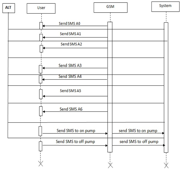 | Figure 26. Sequence diagram |
8. Experimental Result
After finishing all of the SWLD system connections and programming, we’ve carried out a multiple experiments; the developed GSM based system gives good response to the sensor and sends SMS when it detects leakage in water where the water sensor was fixed. The time taken by the system to deliver the SMS is dependent on the coverage area or range of the specified mobile network. If the mobile is in the range of the system, then the SMS is delivered in 4 seconds.
8.1. Test Cases
We recorded the reaction of the device when the leakage was occurring and the results were as follows:Test Case 1:Title: Water leakageSystem: SWLDInput Instructions: Acquire the water sensor (A0) reading while there was leakage in garden pipe 1.Output: Alarming the user on his mobile by sending an SMS to the Android mobile application and close valve1.Result: Test Succeeded.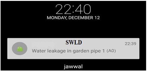 | Figure 27. Result when leakage detected in region 1 |
Test Case 2:Title: Water LeakageSystem: SWLDInput Instructions: Acquire the water sensor (A1) reading while there was leakage in garden pipe 2.Output: Alarming the user on his mobile by sending an SMS to the Android mobile application and close valve1.Result: Test Succeeded.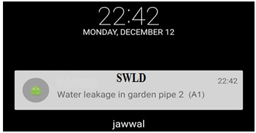 | Figure 28. Result when leakage detected in region 2 |
Test Case 3:Title: Water LeakageSystem: SWLDInput Instructions: Acquire the water sensor (A2) reading while there was leakage in kitchen pipes.Output: Alarming the user on his mobile by sending an SMS to the Android mobile application and close valve2.Result: Test Succeeded.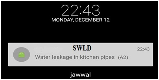 | Figure 29. Result when leakage detected in region 3 |
Test Case 4:Title: Water LeakageSystem: SWLDInput Instructions: Acquire the water sensor (A3) reading while there was leakage in the living bathroom pipes.Output: Alarming the user on his mobile by sending an SMS to the Android mobile application and close valve3.Result: Test Succeeded.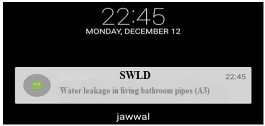 | Figure 30. Result when leakage detected in region 4 |
Test Case 5:Title: Water LeakageSystem: SWLDInput Instructions: Acquire the water sensor (A4) reading while there was leakage in the master bathroom pipes.Output: Alarming the user on his mobile by sending an SMS to the Android mobile application and close valve3.Result: Test Succeeded.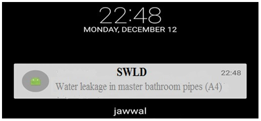 | Figure 31. Result when leakage detected in region 5 |
Test Case 6:Title: Water LeakageSystem: SWLDInput Instructions: Acquire the water sensor (A5) reading while there was leakage in the main bathroom pipes.Output: Alarming the user on his mobile by sending an SMS to the Android mobile application and close valve4.Result: Test Succeeded.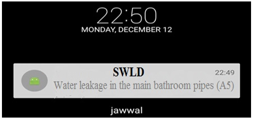 | Figure 32. Result when leakage detected in region 6 |
Test Case 7:Title: Water Level System: SWLDInput Instructions: Acquire the water level sensor (A6) reading while there was decrease in water level.Output: Alarming the user on his mobile by sending an SMS to the Android mobile application and allow the home owner to control in pump through mobile application by sending an SMS to the Arduino to off or on the pump.Result: Test Succeeded.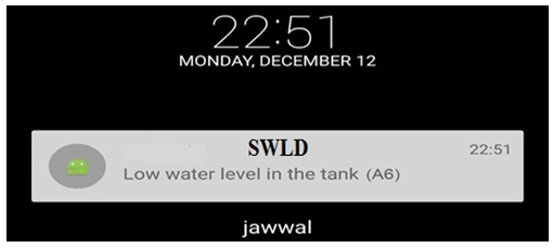 | Figure 33. Result when decrease detected in water level in tank |
8.2. Common Factors Causing Water Leakage
In the coming Figure 35, we have many factors that cause leakage in the plumping of the homes and buildings and also these factors are results of many studies that talks about this issue, in the figure we have the percentage of each factor. As shown below there are many mechanical interruptions that may cause leakage, but as shown the high probability can be referred to the ground movement, pipes corrosion, high system pressure, heavy loading on the hoses and pipes and the pipes age.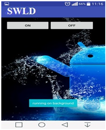 | Figure 34. The choice to turn on/off the pump |
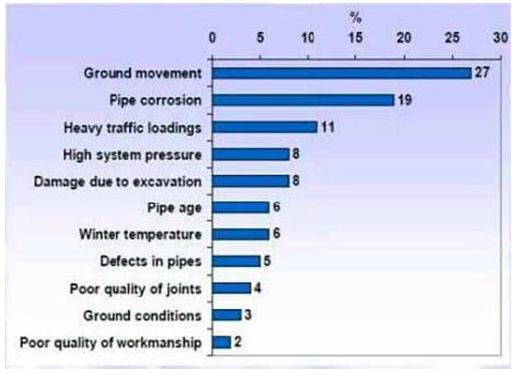 | Figure 35. Percentages to the factors that causes leakage |
8.3. The Response of the Solenoid Valve
As shown in Figure 36, the graph describes how will be the response of the solenoid valve when leakage occurred in pipes and hoses of the plumbing in the home. The selected value that we use to the leakage sensor is 80 mL (microliter); that means when the water leakage sensor detect 80 ml and above, the controller will activate the solenoid valve that means the solenoid will be closed which will result stop supplying water to the track where the leakage occurred.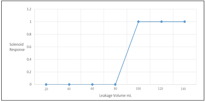 | Figure 36. Solenoid valve response due to leakage volume |
9. Directions for Future Research
The future work which can be added and improved to the system structure of our system is improve an insulation system that will be used to cover and protect the electrical wires which are for the electrical supply and signal of the water sensors, these sensors are distributed on the domestic plumping network. This insulation is important to avoid damage between water hoses and the electrical wires of the sensors. Also, related to the future work of this system, we can apply this technical method of detecting water leakage in the maintenance companies to allow them be able to monitor the plumping networks in the buildings and homes faraway. In addition this application which was produced for the system can be used with maintenance engineer to be notified when and where the leakage occurred to fix the problem directly.
10. Conclusions
The proposed systems are tested on the model of SWLD which is shown in Figure 1. This system feature is expected to draw much attention in the next decades.Water is one of the most important basic needs for all living beings. But, unfortunately a huge amount of water is being wasted by uncontrolled use and uncontrolled leakage. The main issue that is being addressed in this system is about using an efficient wireless sensor based on water monitoring system. Two different ways to monitor the water such as water level monitoring and water pipeline leakage monitoring. Finally, the water monitoring system of homes/offices research concept will be completed by using wireless sensor technology. By using the monitoring system, we can easily prevent the water and the water will be saving to our generation. In our system we mainly depend on technical method which deals with control and features and effective methods for monitoring the plumbing at homes. Based on microcontroller Arduino mega2560 and GSM technology we achieved the main general purpose of this system topic idea which is water leakage detection and wireless control of the water pump. Using GSM technology makes the work more efficient and ease the data translating. Firstly, this make the home owner able to be notified when leakage occurred directly, also the solenoid valves will be closed directly. Secondly, using GSM which deals with mobile allows the home owner to control the water pump whenever the water level is decreased in the tank which will be supplied from the main municipality supply using the pump.
ACKNOWLEDGEMENTS
The authors would like to thank Palestine Technical University – Kadoorie (PTUK) for supporting this research and allowing us to conduct this work in the university labs.
References
| [1] | Zulhani Rasin and Mohd Abdullah International Journal Engineering & Technology, "Water leakage Monitoring System Using Zigbee Based Wireless Sensor Network", 2005. |
| [2] | Misiunas, D., Lambert, M., Simpson, A., Olsson, G. “Burst detection and location in water distribution networks,” Water Science and Technology: Water Supply, 5(3–4), 71–80. (2005). |
| [3] | Bowling, Michael. "Leakage testing method for a plate heat exchanger." U.S. Patent 6,062,068, issued May 16, 2000. |
| [4] | Daadoo, M., Tarapiah, S., & Atalla, S. (2016). Evaluating Efficiency of Multi-Layered Switch Architecture in All-Optical Networks. International Journal of Applied Engineering Research, 11(22), 11030-11036. |
| [5] | Daraghmi, Y. A., & Daadoo, M. (2016). Intelligent Smartphone based system for detecting speed bumps and reducing car speed. In MATEC Web of Conferences (Vol. 77, p. 09006). EDP Sciences. |
| [6] | Motaz Daadoo, Shadi M.A Atallah and Saed Tarapiah. "Development of Low Cost Safety Home Automation System using GSM Network." European Journal of Scientific Research ISSN 1450-2267 Vol. 53 No 3 November, 2016, pp.338-353. |
| [7] | Motaz Daadoo, Saed Tarapiah and Shadi M.A Atallah. “Analysis and Performance of a Low Cost Multiple Alarm Security System for Smart Home Based on GSM Technology and Controlling Based on Android Smartphone." European Journal of Scientific Research ISSN 1450-216X / 1450-202X Vol. 143 No 2 November, 2016, pp.136-165. |
| [8] | Daadoo, M., & Daraghmi, Y. (2015, August). Searching of optimum characteristics of multi-layer switching architecture in all-optical networks. In Heterogeneous Networking for Quality, Reliability, Security and Robustness (QSHINE), 2015 11th International Conference on (pp. 50-55). IEEE. |
| [9] | Tarapiah, S., Atalla, S., Hashim, K. F. B., & Daadoo, M. (2016). Mobile Network Planning Process Case Study-3G Network. Computer and Information Science, 9(3), 115. |

 Abstract
 Reference
 Full-Text PDF
 Full-text HTML