-
Paper Information
- Previous Paper
- Paper Submission
-
Journal Information
- About This Journal
- Editorial Board
- Current Issue
- Archive
- Author Guidelines
- Contact Us
International Journal of Networks and Communications
p-ISSN: 2168-4936 e-ISSN: 2168-4944
2016; 6(5): 98-101
doi:10.5923/j.ijnc.20160605.02

Parallel Data Transmission Using New Line Code Methodology
 Abstract
 Reference
 Full-Text PDF
 Full-text HTML
Juma Abu-Ghalune, Mahmoud Alja'fari
Communication Engineering Department, Faculty of Engineering Technology, AlBalqa Applied University Amman, Jordan
Correspondence to: Mahmoud Alja'fari, Communication Engineering Department, Faculty of Engineering Technology, AlBalqa Applied University Amman, Jordan.
| Email: |  |
Copyright © 2016 Scientific & Academic Publishing. All Rights Reserved.
This work is licensed under the Creative Commons Attribution International License (CC BY).
http://creativecommons.org/licenses/by/4.0/

In this paper we introduce a new line code structure and methodology that will enable us to send two codes in parallel at the same time in one line code without any major loss in the line codes best properties, the new line code structure is based on two common known line codes combined with each other, in the receiver side we introduce a simple separation procedure that will enable us to restore the original user's codes for each user without any possibility of interference between them.
Keywords: Bandwidth, Line code, Synchronous, Power
Cite this paper: Juma Abu-Ghalune, Mahmoud Alja'fari, Parallel Data Transmission Using New Line Code Methodology, International Journal of Networks and Communications, Vol. 6 No. 5, 2016, pp. 98-101. doi: 10.5923/j.ijnc.20160605.02.
Article Outline
1. Introduction
- In telecommunication, a line code (also called digital baseband modulation) is a code chosen for use within a communications system for baseband transmission purposes. Line coding is often used for digital data transport where the binary 1’s and 0’s, such as in PCM signaling, may be represented in various serial–bit signaling formats [1, 6].In line coding, binary data can be transmitted using a number of different types of pulses. The choice of a particular pair of pulses to represent the symbols 1 and 0 is generally made on the grounds of one or more of the following considerations: presence or absence of a DC level, bandwidth efficient, transparency (i.e. the property that any arbitrary symbol, or bit, pattern can be transmitted and received), ease of clock signal recovery for symbol synchronization, and presence or absence of inherent error detection properties [1, 6]. Some of the most popular line codes are unipolar signaling, polar signaling, bipolar (Pseudo ternary) signaling, Manchester signaling. Theses codes are represented as follows:– Unipolar signaling: the binary 1 is represented by a high level (+A volts) and a binary 0 by a zero level. This type of signaling is also called on–off keying (OOK) [2]. – Polar Signaling: Binary 1’s and 0’s are represented by equal positive and negative levels [2]. – Bipolar (Pseudo ternary) Signaling: Binary 1’s are represented by alternating positive or negative values. The binary 0 is represented by a zero level. The term pseudo ternary refers to the use of 3 encoded signal levels to represent two–level (binary) data. This is also called alternate mark inversion (AMI) signaling [2, 7]. – Manchester Signaling: Each binary 1 is represented by a positive half–bit period pulse followed by a negative half–bit period pulse. Similarly, a binary 0 is represented by a negative half–bit period pulse followed by a positive half–bit period pulse. This type of signaling is also called split–phase encoding [5, 8].– Differential Manchester Signaling: A binary 1 bit is indicated by making the first half of the signal equal to the last half of the previous bit’s signal i.e. no transition at the start of the bit-time. A binary 0 bit is indicated by making the first half of the signal opposite to the last half of the previous bit's signal i.e. a zero bit is indicated by a transition at the beginning of the bit-time [6].There are also two major categories for line codes: return–to–zero (RZ) and non return–to–zero (NRZ). With NRZ coding, the waveform has a pulse for the whole bit interval, while in the RZ coding, the waveform returns to a zero–volt level for a portion (usually one–half) of the bit interval [9].Each line code has advantages and disadvantages. For example, the unipolar NRZ line code has the advantage of using circuits that require only one power supply, but it has the disadvantage of requiring channels that are DC coupled (i.e. with frequency response down to f = 0), because the waveform has a non–zero DC value. The polar NRZ line code does not require a DC coupled channel, provided that the data toggles between binary 1’s and 0’s often and that equal numbers of 1’s and 0’s are sent. However, the circuitry that produces the polar NRZ signal requires a negative voltage power supply as well as the positive voltage power supply. The Manchester NRZ line code has the advantage of always having a 0 DC value, regardless of the data sequence, but it has twice the bandwidth of the unipolar NRZ or polar NRZ code because the pulses are half the width [5].Figure 1 shows the waveforms of some line codes as example for the data stream (01101001) by: unipolar (NRZ) signaling, polar NRZ signaling, unipolar (RZ) signaling, bipolar RZ signaling, and Manchester code signaling [2].
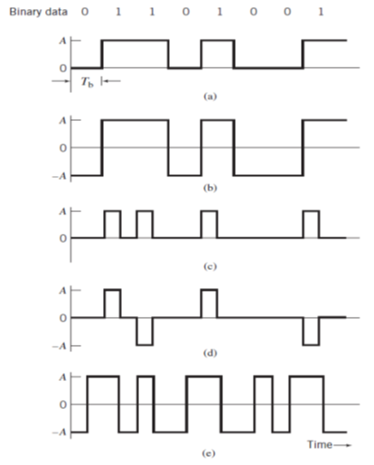 | Figure 1. Line codes for the electrical representations of binary data using: (a) unipolar (NRZ) signaling; (b) polar NRZ signaling; (c) unipolar (RZ) signaling; (d) bipolar RZ signaling; (e) split-phase or Manchester signaling |
2. The New Line Code Structure
- In this paper we introduce a new line code that can be used to transmit two codes in parallel at the same time using the same bit interval of the one bit period. Unlike the other line codes that send one code per a one bit interval [3].
2.1. The New Line Code Values and Shapes
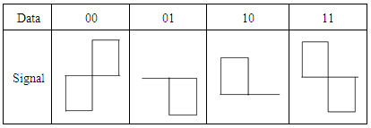
- In our new line code, we take two bits from two different codes, where the first bit is taken from the first code and the second bit is taken from the second code. By this coding strategy we have four combinations of data bits to be sent. The coded data has the following combinations:00, 01, 10, and 11.The new line code can be represented as follow:A 00 is represented by A negative pulse of amplitude A, followed by a positive pulse of amplitude A, with both pulses being half-symbol wide [4].A 01 is represented by A zero space, followed by a negative pulse of amplitude A, with both pulse and space being half-symbol wide [4].A 10 is represented by A positive pulse of amplitude A, followed by a zero space, with both pulse and space being half-symbol wide [5].A 11 is represented by A positive pulse of amplitude A, followed by a negative pulse of amplitude A, with both pulses being half-symbol wide [5].These combinations and its representations can be seen in Table 1.
|
2.2. The Transmission Method
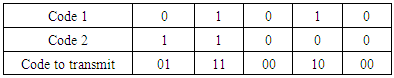
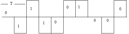
- In our new line code, the transmission strategy can be summarized as follows:a. Combine the two codes bit by bit where the first bit is from the first code and the second bit is from the second code.b. Represent each combination code by its symbol as given up then send it.Let us take an example of transmitting two codes. Consider the codes (01010) and (11000) as an example in our new line code. Table 2 shows the two codes and the coded data according to our new line codes.
|
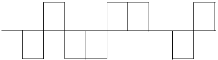 | Figure 2. The wave form for two codes in one line code |
3. Line Code Performance
- In this part, we compare the performance of the new line code proposed on this paper with the most common known line codes.
3.1. Self-Synchronization
- Line coding should make it possible for the receiver to synchronize itself to the phase of the received signal. If the synchronization is not ideal, then the signal to be decoded will not have optimal differences (in amplitude) between the various digits or symbols used in the line code. This will increase the error probability in the received data [15]. Our new line code requires at least one transition per bit time. This makes it easier to synchronize the transceivers, and detect error which occurs in the same bit period.
3.2. Power Spectral Density (PSD)
- The power spectral density function (PSD) shows the strength of the variations (energy) as a function of frequency. In other words, it shows at which frequencies variations are strong and at which frequencies variations are weak [6, 16]. We can note from the shape of the new line code that the new line code is a combination of two codes, Manchester and polar RZ. Thus our new line code PSD is an average of the PSD of two codes Manchester and Polar RZ codes [17]. Thus the PSD for our new line code in this paper is as shown in Figure 3.
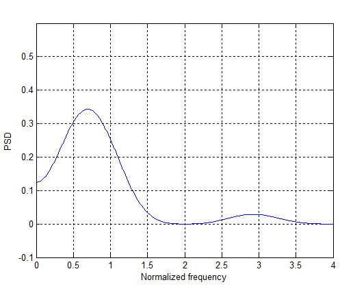 | Figure 3. The PSD for the new line code |
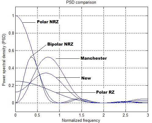 | Figure 4. The PSD comparison |
3.3. The Bandwidth Efficiency
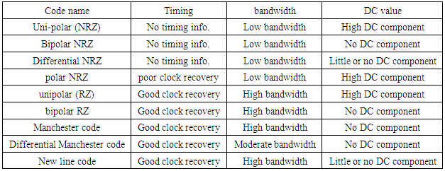
- It is very clear from Figure 4 that the bandwidth consumed by the new line code is exactly the same as the bandwidth of the Manchester code [8, 18]. This bandwidth is used to transmit two codes at the same time using our new line code. Table 3 shows a comparison of the performance of our new proposed line code with the most common known line codes from the points of bandwidth, DC value, and the ability of clock extraction.
|
3.4. The Transmission Hardware
- The hardware component is very simple because we don’t have a bipolar behavior, so it well be like a Manchester code transmitter with some modifications.
4. Decoding Algorithm
- The decoding procedure is done by separating the new line code into two codes as follow:a. The first code refers always to the positive part (upper side) of the new line code while the second code refers to the negative part (lower side).b. In the upper side if the user data is one then the positive value will be in the first half of the bit period elsewhere it is zero.c. In the lower side if the user data is one then the negative value will be in the second half of the bit period elsewhere it is zero.By applying this procedure we can decode the proposed example seen in figure 2 as follows:
 User 1 code is:
 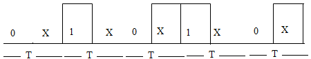 Then the code will be: 0 1 0 1 0User 2 code is:
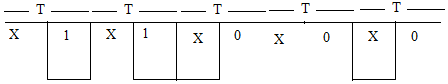 Then the code will be: 1 1 0 0 0
 5. Conclusions
- The new line code proposed on this paper achieves a good performance on the points of clock recovery, PSD, and bandwidth efficiency comparing with the most common known line codes, but the biggest advantage is the capability of sending two codes at the same time in one line code which means a conservation of bandwidth.