-
Paper Information
- Paper Submission
-
Journal Information
- About This Journal
- Editorial Board
- Current Issue
- Archive
- Author Guidelines
- Contact Us
International Journal of Networks and Communications
p-ISSN: 2168-4936 e-ISSN: 2168-4944
2016; 6(4): 80-86
doi:10.5923/j.ijnc.20160604.03

On GPS Fault-Tolerance for City-Bus Tracking System Using Wireless Sensor Networks
 Abstract
 Reference
 Full-Text PDF
 Full-text HTML
Sharhabeel H. Alnabelsi
Computer Engineering Department, Al-Balqa Applied University, Al-Salt, Jordan
Correspondence to: Sharhabeel H. Alnabelsi, Computer Engineering Department, Al-Balqa Applied University, Al-Salt, Jordan.
| Email: |  |
Copyright © 2016 Scientific & Academic Publishing. All Rights Reserved.
This work is licensed under the Creative Commons Attribution International License (CC BY).
http://creativecommons.org/licenses/by/4.0/

In modern crowded cities, public transportation is one of primary ways for people to go to work, shopping, etc. Therefore, it is necessary to provide an application which estimates buses’ real-time current location, supported by Google map application which displays bus location and expected arrival time. In this work, we propose a city-bus tracking system which contains two localization methods: First, using GPS method. Second, a fault-tolerance method using Wireless Sensor Networks (WSNs), in case of GPS signal failure, e.g.; due to weather conditions or physical obstacles. In this method, wireless sensor boards are deployed in selected locations along buses routes in city, and each bus is equipped by a wireless sensor board and GPS. When GPS signal is bad, the second method is considered, where bus-sensor node sends a “Hello” packet, while bus moving, to nodes deployed over bus route. Based on the Received Signal Strength Indicator (RSSI) and number of route nodes which received the “Hello” packet, the proposed localization method is used to estimate bus location.
Keywords: Localization, WSNs, Fault-tolerance, Route node, Bus node
Cite this paper: Sharhabeel H. Alnabelsi, On GPS Fault-Tolerance for City-Bus Tracking System Using Wireless Sensor Networks, International Journal of Networks and Communications, Vol. 6 No. 4, 2016, pp. 80-86. doi: 10.5923/j.ijnc.20160604.03.
Article Outline
1. Introduction
- In modern cities, a lot of people such employees use buses for transportation, therefore, it becomes necessary to provide an accurate and reliable system for bus tracking and their expected arrival time to the intended bus station, which can be web based and accessible from smart mobile phone application.In this work, a city-bus tracking system has been designed with the goal of creating a pervasive computing environment for bus riders and providing a reliable tracking system for dispatchers. Using web enabled devices, riders are able to access real time bus locations with little effort or awareness of the enabling infrastructure. Similarly, dispatchers are able to monitor the locations of all buses regardless of route conditions that have the potential to cripple other tracking systems, e.g.; GPS. Much of the infrastructure necessary to create this system has been implemented in a simple proof of concept demonstration. When GPS localization device fails, a fault-tolerance method is proposed in this work empowered by Wireless Sensor Networks (WSNs), in order to estimate the real-time bus location, such that bus arrival time is calculated. This work is organized as follows: Section 2 presents the related work. System model components and contributions are explained in Section 3. A novel localization method is explained in Section 4. Section 5 presents challenges faced in this work and their solutions. Section 6 discusses results demonstration. In Section 7, alternative system models are discussed. Finally, section 8 presents conclusions.
2. Related Work
- Many vehicle tracking systems exist today. Companies such as NextBus Inc. and Connexionz market products specifically designed for bus tracking to cities and campuses around the world. While each system is unique, the basic structure is the same: A GPS unit on each bus sends coordinates wirelessly to a central server where the data is processed and user requests are serviced.A tracking bus system is proposed in [1], to detect the bus arrival time at bus stations using wireless sensor networks. Also, a smart bus monitoring system is proposed in [2], in which RFID and GPS are employed to monitor bus when arrives to stations, such that each bus has an RFID reader, GPS, and GPRS transmitter. Each bus station is equipped by an RFID Tag. When bus approaches bus stations the RFID Tag and RFID reader communicate, and therefore, the General Packet Radio Service (GPRS) is activated and sends the current bus location and arrival time stamp. Authors in [3], proposed to deploy at each bus station an Arduino microcontroller and RFID receiver, while each bus is equipped by RFID tags. When bus arrival is detected at a bus station, data message sent to central scheduler, in order to estimate bus location and estimated arrival time. RFID technology and wireless sensor networks are also used in [4], in which bus arrival to stations entrances is detected, and data sent to a central computer that estimate arrival time to next stations. Using cellular network, a bus locator system is proposed in [5], in which passengers on buses, called sharing users, their installed data collection module on smart phones starts to get cellular towers IDs sequence, while passengers are travelling on bus. Then, server starts analysing received IDs through cellular network, in order to estimate bus location. In [6], a classic vehicle tracking system is developed using GPS and GPRS which gives the vehicle position on the road. Authors used Google map API to display bus location on smart phones.In [7] using WSNs, a localization method is proposed based on channel propagation model that uses the log-normal shadowing model and RSSI, in order to estimate the distance between a sensor mote mounted on an object such as bicycle and an anchor node, e.g.; coach. Authors in [8] utilize WSNs and RSSI notion, in order to detect the presence of human in a given location. Also, various localization algorithms in WSN are discussed in [9], such as range-based and range-free techniques. Depending on transmission angle for the directional antenna and energy consumption for transmitting data, a localization method is proposed in WSNs [10]. Based on RSSI and the trend of RSSI values that received from beacons, a localization method is proposed to estimate the position of sensor nodes [11]. Also, an evaluation of a feedforward artificial neural networks training method that developed for object localization in WSNs is presented in [12], their work use RSSI from anchor nodes under the effect of multi-path propagation effects. The importance of the proposed city-bus localization method in this work, because it supports a fault-tolerance technique empowered by a multi-hop WSN when GPS signal fails. Also, when GPS fails, the accuracy of location estimation is based on more than one received beacon from route nodes that heard the city-bus “Hello” message, and therefore, the localization accuracy is improved.
3. System Model and Contributions
- The proposed advanced bus tracking system, that provides GPS fault-tolerance model consists four major components, as shown in Figure 1:
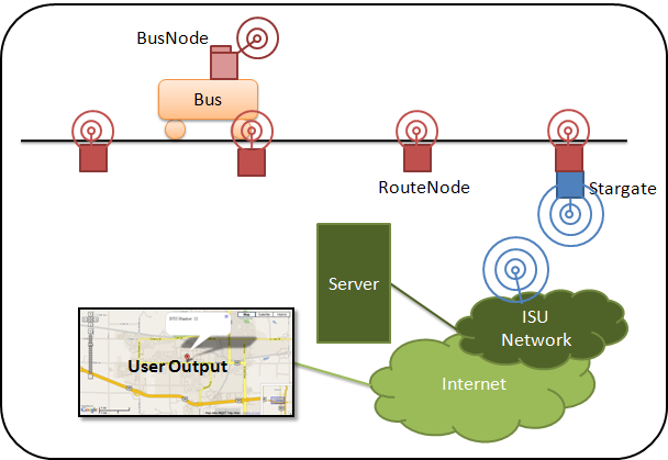 | Figure 1. The proposed city-bus tracking system architecture |
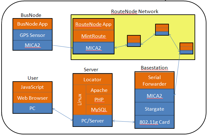 | Figure 2. The four system components and communication paths between components and user (Orange color indicates software parts and blue indicates hardware parts) |
3.1. Bus Node
- Each bus node is composed of a MTS420 GPS sensor board mounted on a MICA2 wireless transceiver. A single program written in Tiny OS 1.1 processes readings from GPS sensor and sends packets over the MICA2 radio. Every bus that is tracked must be coupled with a bus node. It is worth mentioning that GPS board is connected serially with MICA2 mote through USART1 interface port. Also, GPS board operates on a higher voltage than MICA2 sensor board, e.g.; 3.3v, which can be gained from the bus itself. As the bus is driven along its route in the city, the bus node transmits data location whenever a new GPS reading is available. In addition to latitude and longitude, the GPS reading also contains: (1) - An accurate time-stamp in UTC. (2) - An indication of signal quality through the number of visible satellites. This information is parsed from the GPS signal and placed in a GPS message structure. Figure 3 shows the information contained in the GPS message structure. Data to fill the “First Hop ID” and “Signal Strength” fields are not known at the Bus Node, so a ‘1’ is entered in each of these fields.
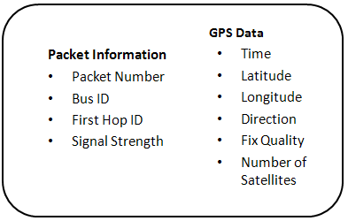 | Figure 3. A GPS message can be broken into packet identifying packet information and GPS data |
3.2. Multi-hope Routing Component
- A routing protocol between deployed route nodes along roads is defined in the “MintRoute” program, which is defined as a multi-hop routing component provided with Tiny OS 1.1. Route nodes use this program to efficiently forward packets to Stargates boards. Each route node forwards received packets to its parent, whose node ID is stored and periodically updated. To update parent nodes, route node ‘0’ transmits an update packet, which allows each node to update their parent node based on the received hop count and signal strength. This ensures that packets are routed toward stargate efficiently such that the end-to-end transmission delay is minimized [13].It is possible that multiple route nodes receive the same GPS message from a single bus node. Each of these route nodes adds their respective First Hop ID and Signal Strength to the GPS message and forwards it to closest Stargate device. When more than one route node receive a packet (based on the granularity of nodes deployment along the road), the proposed localization algorithm is used, explained in section 4, in order to calculate more accurate bus location.
3.3. Route Node
- Each route node is composed of a single MICA2 wireless transceiver running two programs: (1) - The route node application program receives GPS messages from bus nodes. (2) - The MintRoute program routes messages to Stargates device boards. Both of these processes are able to listen to the radio simultaneously and only handle packets intended for them. This design feature was easily implemented using Tiny OS 1.1 components.Route node application performs a small amount of processing, before sending the GPS message over the route node network. A packet's signal strength indicates transmission distance and is needed for triangulation. It is automatically added to every packet received by the MICA2 radio, but is not transmitted if the packet is forwarded directly. Tiny OS 1.1 provides easy access to the signal strength data, such that the route node application retrieves and adds it to the GPS message. Also, it fills the First Hop ID field, where the GPS message is ready to be transmitted over the route node network. Route nodes in the city roads are devised into cluster, such that in each cluster only one route node is physically attached to a Stargate via 51-pin connector. Rather than forward packets to the radio and route node network, this node sends all packets to the serial connection with the Stargate. The current design requires these nodes to have node ID ‘0’ for the routing protocol to function properly.
3.4. Stargate
- Stargates are single board computers which can be customized for a wide variety of tasks. In the proposed advanced bus tracking system, Stargates is used with a Netgear MA701 Wireless Compact Flash Card [14], in order to interface route nodes network with Wi-Fi internet access. Adding Stargates to the system forms a multi-tier communication network with much greater range than a MICA2 network alone. This allows the server to be located anywhere with internet access rather than requiring it to be within the range of the route nodes network. However, it requires that each Stargate to be within the range of a close Wi-Fi access point in the city, or within the range of another Stargate that is connected to an internet gateway. A Route Node with ID ‘0’ is physically mounted on each Stargate via a 51-pin connector, which is recognized by the Stargate as a serial port. Any network packets received by route node 0 are forwarded to the serial connection. The Stargate runs a simple serial forwarding program that makes the packet data available on a predetermined TCP/IP port, in which packets can be transmitted to server.
3.5. Server
- The server fulfills two functions: (a) - Determines bus locations from collected data. (b) - Reply to users requests. These two functions have been implemented using the LAMP solution stack software, in which a Linux OS, an Apache web server, a MySQL database manager, and PHP programming language. When server receives user’s request asking for bus location, server starts collecting the most recent buses locations information that available from the Stargates. Any new data is added to a buffer which holds recent locations information for all buses. As new data for a bus arrives to server, it overwrites that bus oldest data in cache. The goal is to have multiple recent packets for each bus available, so that triangulation is possible when the GPS reading cannot be acquired, e.g.; due to weather conditions. Note that more densely deployed route nodes over roads means the original GPS packet will be received by more route nodes close to bus location.
4. Localization Method
- When the system receives a user request to know city-bus location, the locator algorithm is called to determine the bus locations. In order to estimate city-bus location using the deployed wireless sensor network, which consists the bus node and the route nodes along city-bus route while the bus driven over the road, some route node(s) receive the “Hello” message from bus node (which implies the bus is here), as shown in Figure 4. If a valid GPS data has been cached for a bus, the algorithm matches this data to the closest possible bus location. Otherwise, when GPS fails, the algorithm finds the best match location using the first hop and signal strength data from cache and data from database tables. As shown in Figure 4, the dotted arrows indicate a GPS message from bus node sent to route nodes within its transmission range. Multiple route nodes receive the packet, allowing the locator function in server to triangulate current bus position. Note that a limited set of route nodes will receive the packet from the bus node.
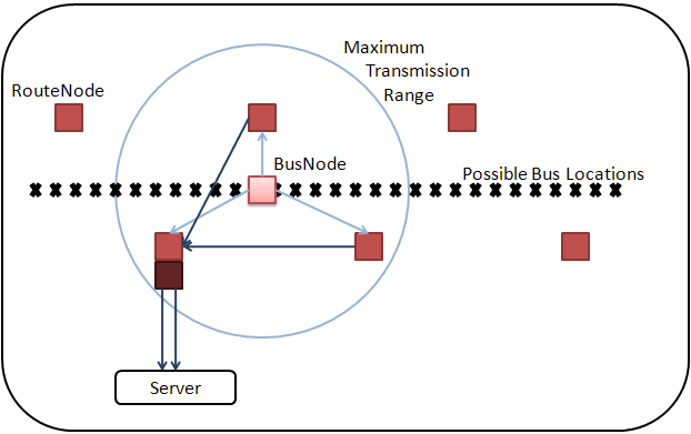 | Figure 4. A sketch for wireless senor network topology, in order to estimate city-bus location when GPS fails |
 | (1) |
 | (2) |
 | (3) |
5. Challenges
- Designing the advanced city-bus tracking system faced several challenges. This section lists some of these significant challenges and the solutions that were developed.
5.1. GPS Power Supply
- The GPS receiver on the sensor board operates at 3.3 volts as suggested by its manufacturer, which is not possible to achieve using two standard AA or AAA batteries. When underpowered by the batteries, the GPS receiver does not perform satisfactorily with the MICA2 transceiver, where some radio packets are dropped. Additionally, on-line discussions suggest shielding the GPS chip to prevent interference with the MICA2 radio.In order to construct a working demo system, a simple voltage divider was added to a five volt, one amp AC power adapter (specifically, the Stargate power adapter). By supplying the required voltage to the GPS unit, its signal quality improved significantly. However, this approach made outdoor testing difficult. Thus, an alternative modification involving in-car cigarette-lighter plug should solve the power issue on a bus.
5.2. Localization
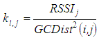
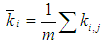
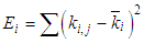
- The received signal strength indicator (RSSI) is part of every received Tiny OS packet. However, Tiny OS documentation does not contain any official statements discussing the relationship between the RSSI value and actual communication conditions. Browsing through other users' experiences resulted in a wide variety of results. Many questioned the reliability of RSSI as a distance indicator because of environmental inconsistencies. Following the results in [15, 16], it was decided that the proposed bus tracking system would assume RSSI to be proportional to transmission distance squared in an open outdoor environment. This is meant to serve as a starting point based on the most reliable data and can be changed if location results are inaccurate. In addition, the locator algorithm compares RSSI values from many MICA2 transceivers in the same general area. This ensures that weather conditions do not affect localization results, although environmental conditions that affect a single MICA2 still have the potential to cause localization errors.
5.3. Server Load
- In anticipation of large server loads with a scaled up system, the server delays the location estimation process until it receives a user request. The actual computation may be further off-loaded from the server to the client, which can use Java script to perform calculations locally. Note that Java script is already required at the client-side in order to display the Google Map, so no additional software is necessary.
6. Results Demonstration
- This system was implemented using MICA2 wireless modules [19] and Stargate single board computers [20] from Crossbow Technology, Inc [21]. The MICA2 were programmed using Tiny OS version 1.1 [22] with a significant portion of the programming based on provided examples and components. The server was designed to use the LAMP software solution stack. The final user output consists of a Google Map with the most recent bus locations indicated. Also, to implement the system three database tables may be referenced when calculating a bus location, if GPS signal fails: (1) - The "Route Node Locations Table": contains the fixed locations of all deployed route nodes along the road. (2) - The "Visible Locations Table": identifies which possible bus locations can be seen by which route nodes. (3) - The "Possible Bus Locations Table": contains a set of possible locations for the bus. Possible bus locations are spaced approximately 30 feet apart and each location is associated with all route nodes that are within communication range. These three tables are initialized prior to system operation and remain constant unless manually updated.In order to determine bus locations, tables within the database must be filled with useful, accurate data. For the demo purpose, these tables were filled with a small amount of generic data to demonstrate system capabilities, but these tables would be much larger in an actual deployment with each entry requiring individual attention. An end-to-end version of this system was implemented and tested as a proof of concept demonstration. The demo simulated a single bus with a very limited route (three route nodes) and a single Stargate. For convenience, the server was implemented on the Stargate with limited functionality in the locator algorithm. The Google Map page was accessible through the internet and displays city-bus location.In preparation for the demo, the GPS sensor and bus node were tested outdoors. Results of these limited tests showed that the GPS sensor could acquire a GPS signal within approximately three minutes when kept in one location. Moving the sensor at bus speeds could significantly increase this time, although this was not tested. As expected, the accuracy of GPS readings was found to decrease significantly when tall buildings and trees obstructed large portions of the sky. Because the bus will be moving through an area with much of the sky obstructed, therefore, these observations validated the need for the alternative localization method. On the other hand, the consumed power by sensors was not measured, since it depends on transmission range, size of transmitted data, and overall time in which radios are active. However, Crossbow [21] provides enough details for energy consumption in MICA2 sensor and GPS boards. Also, authors in [23] have provided some measurements for MICA2 module.
7. Alternative Models
- This design focuses on creating a system using the GPS sensor to provide bus position, in addition to wireless sensor networks which requires using MICA2s and Stargates to form routing network. Several alternatives were considered, however, this design was chosen due to the availability of hardware, reliability of the system, and the desire to work with wireless sensor networks. The Following subsections are a list of other possible alternative architectures.
7.1. CB Radio
- Each city-bus is equipped with a CB radio (short distance transmission device) for communication with dispatchers and other buses. It may be possible to develop hardware which encodes GPS information and transmits through CB radio. Additional hardware would be required for the interface with server and to decode the received information signal. It is possible that this approach would interfere with regular CB voice communication; hence, another dedicated channel is required. The design was not chosen due to a lack of hardware.
7.2. Cellular Networks
- This approach is similar to the CB Radio approach, but uses existing cellular networks for communication between city-bus and server. Less hardware development would be required and data transfer may be possible using text messages. This design was not considered, because it requires a purchase of expensive GPS capable cell phones and cellular subscription fees.
7.3. Remove GPS Sensor
- Using MICA2 wireless transceivers, a fairly dense routing network can be created, resulting in more accurate resolution of the city-bus location estimation. It is possible that the accuracy of this design may become close to the accuracy of GPS readings. Using this approach, the reliability issues of GPS is avoided. This design alternative was not chosen because the increased number of MICA2s is very expensive compared to the price of a single sensor board for each bus.
7.4. Replace GPS with RFID
- Rather than using a MICA2 and GPS sensor on bus, it may be possible to use an active RFID technology. This would significantly reduce the system cost. In addition to the design accuracy limitations, several issues in this design do not allow to adopt this design such as: Can an RFID reader provide sufficient performance and detection range? What is the level of difficulty in interfacing an RFID reader with a communication network? Would batteries have sufficient energy to power an RFID reader and route node for a long period of time?
8. Conclusions
- This work proposes a fault-tolerance approach using Wireless Sensor Networks (WSNs), when GPS fails, e.g.; due to physical obstacles or weather conditions, to determine city-bus location.In this approach, a set of wireless sensor nodes are deployed along road of bus route. Each bus is mounted by a GPS device and wireless senor node, which periodically transmits GPS data packet or “Hello” message (employed when GPS fails) to route nodes with its transmission range. Route node(s) which receive this packet re-transmit data packet using the multi-hop network which devised by route nodes to Stargate, then the startgate transmits it to the server through TCP/IP port. If a bus passenger asks for city-bus location, the designated server replies with required collected data, and then, bus location is displayed using Google Map Application. Note that the proposed localization algorithm is executed at client side; therefore, calculations overhead is reduced at server if the system is scaled up. In out-doors hardware demonstration, results show the effectiveness of the proposed model and the necessity of the proposed GPS fault-tolerance localization method.