-
Paper Information
- Paper Submission
-
Journal Information
- About This Journal
- Editorial Board
- Current Issue
- Archive
- Author Guidelines
- Contact Us
International Journal of Networks and Communications
p-ISSN: 2168-4936 e-ISSN: 2168-4944
2016; 6(3): 49-56
doi:10.5923/j.ijnc.20160603.02

An Efficient Secured Turbo Codes for Long Term Evolution System Enhancement
 Abstract
 Reference
 Full-Text PDF
 Full-text HTML
M. E. Abd El-Hameed1, Mohsen A. M. El-Bendary2, I. O. Bekhiet3, H. M. Abd El-Kader3
1Worker University, Egypt
2Department of Communication Technology, Faculty of Industrial Education, Helwan University, Egypt
3Department of Electonics and Communication, Faculty of Engineering, Banha University, Egypt
Copyright © 2016 Scientific & Academic Publishing. All Rights Reserved.
This work is licensed under the Creative Commons Attribution International License (CC BY).
http://creativecommons.org/licenses/by/4.0/

In this paper an efficient secured interleaver is utilized in Turbo codes for Long Term Evolution (LTE) system. The engine of the presented technique is the Baker formula; it works based on secret key. The proposed technique system improves the Bit Error Rate (BER) and the throughput as well as the security also. This scheme depends on chaotic Baker map encryption. A comparison study between the proposed chaotic interleaving scheme and the traditional block and convolutional interleaving schemes for LTE system transmission over an Additive White Gaussian Noise (AWGN) channel is presented. The simulation results show the superiority of the proposed scheme over the traditional schemes. It reveals also, the turbo codes perform better with the proposed technique compared to the internal block interleaver used in LTE system. The data ordering in the proposed scenario based on the determined key length, this key controls the power of data randomizing. It can be used as a secret key also, to enhance the LTE security, packet-by-packet protection.
Keywords: LTE, Turbo codes, Interleaver, Baker map, Packet protection
Cite this paper: M. E. Abd El-Hameed, Mohsen A. M. El-Bendary, I. O. Bekhiet, H. M. Abd El-Kader, An Efficient Secured Turbo Codes for Long Term Evolution System Enhancement, International Journal of Networks and Communications, Vol. 6 No. 3, 2016, pp. 49-56. doi: 10.5923/j.ijnc.20160603.02.
Article Outline
1. Introduction
- The company Long Term Evolution [1] has long been seen as the first advancement towards stronger, faster and more efficient 4G data networks. LTE has been developed to meet the requirements of this era and to realize the aim of achieving global broadband mobile communications. The objectives of this evolved system includes higher radio access data rates, improved system capacity, coverage, flexible bandwidth operations, improved spectral efficiency, low latency, reduced operating costs and seamless integration with the Internet and existing mobile communication systems [2]. The technology under LTE can currently reach downlink peak rates of 100Mbps and uplink speeds of 50Mbit/s. The LTE technology is also a scalable bandwidth technology for carriers operating anywhere from 20 MHz to 1.4 MHz. Long Term Evolution offers some excellent advantages over current 3G systems including higher throughput, plug and play compatibility, Frequency Division Duplexing (FDD) and Time Division Duplexing (TDD), low latency and lower operating expenditures. It also offers legacy modes to support devices operating on General Packet Radio Service (GPRS) systems, while supporting seamless pass- through of technologies operating on other older cellular towers. The technologies put forth by LTE will not only be implemented over time, they are designed to be scalable. This scalability means can slowly introduce LTE technologies over time.
2. LTE Physical Layer
- In the base station and one in the mobile station with a channel bandwidth is 20 MHz. One key feature of LTE systems is the support of a scalable channel bandwidth that ranges from 1.4 MHz up to 20 MHz, which makes its implementation more feasible to the service providers. As we see in Fig. 1 the LTE block diagram consist of:
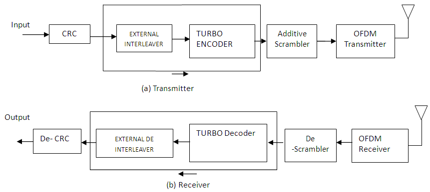 | Figure 1. Block Diagram of LTE System |
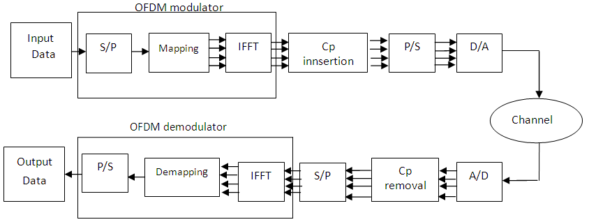
 | (1) |
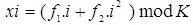 | (2) |
 | (3) |
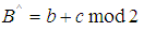
 | Figure 2. OFDM Transmitter and Receiver |
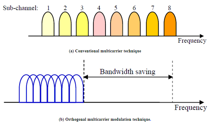
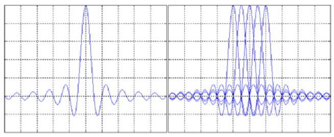 | Figure 3. Spectra of (a) an OFDM sub-channel and (b) and OFDM signal |
 | Figure 4. Representation of OFDM signal [5] |
3. Turbo Coding in LTE
- Turbo codes were first introduced by Berrou, Glavieux and Thitimajshima in 1993 and have Performances within a few tenth of a dB from the Shannon limit. The Turbo encoder in LTE [9] is a code Parallel Concatenated Systematic Convolutional (PCCC) with two 8-state constituent encoders the same as in Universal Mobile Telecommunications Service (UMTS) and one Turbo code contentions free internal interleaver (different from UMTS). The encoders are based on RSC (Recursive Systematic Convolution) codes and their generator polynomial is given by G=[1, g0/g1], where g0=[1011] (Feedback) and g1=[1101] (feed forward). The structure of the Turbo encoder used in LTE is shown in Fig.5, the output of the LTE Turbo encoder consists of three parts, a systematic bit and two parity bits. The systematic bit (Xk) is the untouched input bit. The first parity bit (Zk) is the output of the first convolutional encoder with the original input (Ck) input and the second parity bit (Z0k) is the output of the second convolutional encoder after interleaving (by the Turbo code internal interleaver) of the input bit (C0k) as its input For trellis termination the tail-bits X0k are inserted [8] [9].A. Interleaver role in turbo codeInterleaver size and structure considerably affect turbo code error performance [10]. Turbo codes consist of a parallel concatenation of two Recursive Systematic Convolutional (RSC) coders in conjunction with an interleaver and associated decoder as shown in Fig.4. Interleavers in Turbo code can be categorized as traditional and random types. Traditional interleavers consist mainly of a block interleaver and a convolutional interleaver [1]. Currently, the random interleaver attract much attention since it can contribute not only to correct abrupt errors occurred in signal transmission but also to enhance the randomness of code sequences resulting in lowering the BER and frame error rate (FER) of the communication system. However, it’s difficult in practice to realize the pure randomness in interleaver’s design based on current techniques. As regard to the implementation of the Turbo codes, there are two main obstacles including algorithm complexity and system delay for the Turbo codes being employed into digital communication system in the near future. The main contribution for performance on Turbo codes in system is interleaving and decoding.
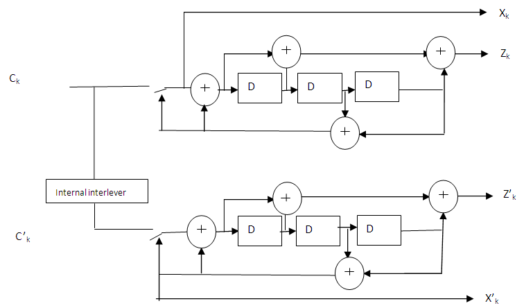 | Figure 5. Structure of the LTE Turbo Encoder |
4. Proposed Modifications
- We study the feasibility of data interleaving prior to transmission over LTE system. The paper presents a new chaotic interleaver and compares to the traditional block and convolutional interleavers.A. Block Interleaver SchemeThe block interleaving is used with turbo decoder in LTE system, the data is rearranged into a matrix in a row-by-row manner, and then read from the matrix in a column-by-column manner.B. Convolutional Interleaver SchemeA convolutional interleaver [4] [11] consists of N rows of shift registers, with different delay in each row. In general, each successive row has a delay which is J symbols duration higher than the previous row as shown in Fig.6. The code word symbol from the encoder is fed into the array of shift registers, one code symbol to each row. With each new code word symbol the commutator switches to a new register and the new code symbol is shifted out to the channel. The i-th (1 ≤ i ≤ N-1) shift register has a length of (i-1)J stages where J = M/N and the last row has M-1 numbers of delay elements.C. Chaotic Interleaver SchemeAs mentioned in the previous subsection, the block interleaver is not efficient with 2-D error bursts. As a result, there is a need for an advanced interleaver for this task. As we see in Fig.7 the 2-D chaotic Baker map [12] [13] in its discretized version is a good candidate for this purpose. After rearrangement of bits in to a 2-Dformat, the chaotic Baker map is used to randomize the bits. The discretized Baker map is an efficient tool to randomize the items in a square matrix. Let B(n1, . . . , nk), denote the discretized map, where the vector, [n1, . . . nk], represents the secret key, Skey. Defining N as the number of data items in one row, the secret key is chosen such that each integer ni divides N, and n1+. . . ,+nk = N. Let Ni =n1+. . . ,+ni−1. The data item at the indices (r, s), is moved to the indices:
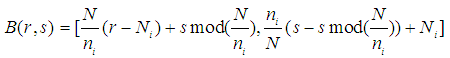 | (4) |
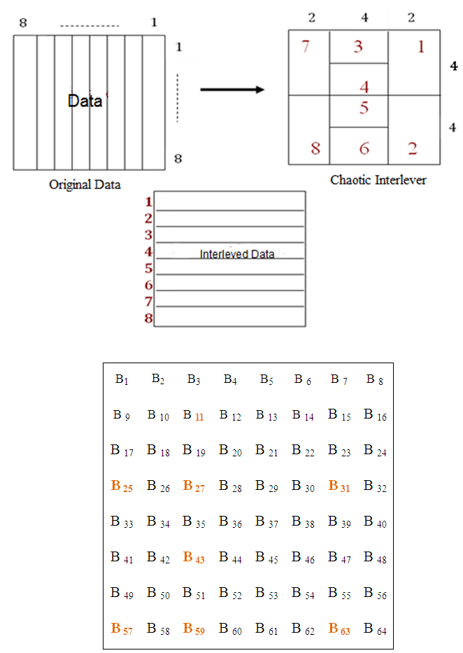
 In steps, the chaotic permutation is performed as follows:1. An N×N square matrix is divided into N rectangles of width ni and number of elements N.2. The elements in each rectangle are rearranged to a row in the permuted rectangle. Rectangles are taken from left to right beginning with upper rectangles then lower ones.3. Inside each rectangle, the scan begins from the bottom left corner towards upper elements.Fig. 7 shows an example for chaotic interleaving of an 8 × 8 square matrix (i.e., N = 8). The secret key, Skey = [n1, n2, n3] = [2, 4, 2]. Note that, the chaotic inter-leaving mechanism has a better treatment to both 1-D and2-D error bursts than the block interleaving mechanism. Errors are better distributed to bits after de-interleaving in the proposed chaotic interleaving scheme. This Skey controls the matrix segmentation and the interleaved data arranging. This key can be changeable and long to enhance the security. So, the Turbo code performance will be developed with security bonus [14].
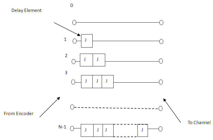 | Figure 6. Convolutional Interleaver |
 | Figure 7. Mechanism operation of the proposed interleaver with 8 8 matrix data size |
5. Simulation Results
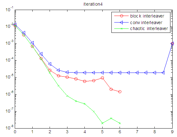
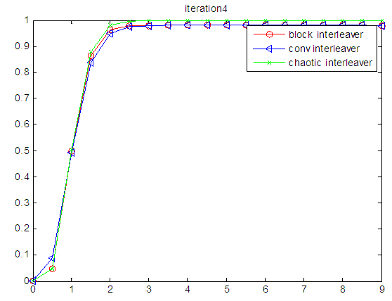
- After the Baker map chaotic interleaving implemented by the step 1 to step 3 and as can be seen from the algorithm steps, it’s easy to design the interleaver in practice. And the overall performance for Turbo codes will be enhanced significantly Another advantage of the proposed interleaver is that during the chaotic mapping only a few parameters are needed being transferred from transmitter to receiver, thus not only we can save channel volume for transmitting more source data on the one hand, but also decrease the probability of data error occurred in the signal transmission on the another. To verify the effectiveness of the proposed interleaver, BER performance compared with other interleavers from the simulation results are given as curves shown in Figs. 8 and 9 respectively. As can be clearly seen from the curves shown in the figure, with reducing the computation complexity the proposed interleaver exhibits a high BER performance than other random interleavers. From the Figs 8 and 9, we found that the throughput also improved from the other interleavers.
 | Figure 8. BER versus SNR for LTE system with chaotic interleaver on AWGN Channel techniques |
 | Figure 9. Throughput of LTE System with Chaotic Interleaver on AWGN Channel Techniques |
6. Conclusions
- This paper presented a simple and efficient novel chaotic interleaver for the transmission of data over LTE system. A comparison study between the proposed interleaver and the conventional interleavers has been presented. The computer simulation results have revealed the effectiveness of the proposed interleaver at medium and high SNR values. Also, the proposed interleaver enhanced the security level as it is based on chaotic map encryption.