-
Paper Information
- Next Paper
- Paper Submission
-
Journal Information
- About This Journal
- Editorial Board
- Current Issue
- Archive
- Author Guidelines
- Contact Us
International Journal of Networks and Communications
p-ISSN: 2168-4936 e-ISSN: 2168-4944
2016; 6(2): 24-31
doi:10.5923/j.ijnc.20160602.02

Comparing Shell Mapping to Trellis Shaping as Symbol Mapping for Co-existence of next Generation PON and Current System
 Abstract
 Reference
 Full-Text PDF
 Full-text HTML
Yasuyuki Okumura, Katsuyuki Fujii, Kohei Oowaki
Department of Science and Engineering, Nanzan University, Aichi, Japan
Correspondence to: Yasuyuki Okumura, Department of Science and Engineering, Nanzan University, Aichi, Japan.
| Email: |  |
Copyright © 2016 Scientific & Academic Publishing. All Rights Reserved.
This work is licensed under the Creative Commons Attribution International License (CC BY).
http://creativecommons.org/licenses/by/4.0/

This paper describes the results of comparing shell mapping to trellis shaping in terms of symbol mapping that can improve the transmission characteristics of next generation Passive Optical Network (PON) system when co-existing with the conventional system. A mapping proposal solves one of the most critical problems; the small Euclid distance of the PSK signals in a constellation shared by OOK and PSK. The conventional system uses on-off keying (OOK) for its simplicity, while the next generation uses advanced techniques such as phase shift keying (PSK). Constellation sharing and the use of Digital Signal Processing technology can allow the next generation PON to co-exist with the conventional system, which is advantageous for the migration of the access network. Shell mapping and trellis shaping are simple and effective symbol mapping approaches for signal shaping algorithms that can maximize the symbol distance assuming the co-existence of OOK and PSK. This paper shows the operating principles of symbol mapping, and also describes the co-simulation configuration of MATLAB and OptSim used to clarify the improvement achieved by the mapping. It shows that trellis shaping improves BER more than shell mapping, and so enables smooth migration from conventional PON to the next generation.
Keywords: Constellation Sharing, Next generation PON, Signal Shaping
Cite this paper: Yasuyuki Okumura, Katsuyuki Fujii, Kohei Oowaki, Comparing Shell Mapping to Trellis Shaping as Symbol Mapping for Co-existence of next Generation PON and Current System, International Journal of Networks and Communications, Vol. 6 No. 2, 2016, pp. 24-31. doi: 10.5923/j.ijnc.20160602.02.
Article Outline
1. Introduction
- Passive optical networks (PONs) deliver not only various services such as the Internet, video, and voice at the same time, but also outstanding flexibility and scalability. In recent years, services for healthcare, education, and mobile backhaul for advanced mobile communications have also moved to optical networks. The demand for these services is spurring research into the next generation PON that should provide sufficient bandwidth and flexibility to meet the requirements. Network operators want these benefits while still operating existing access networks, so the telecom industry is interested in the incremental adoption of the next generation PON [1-9].Several prospective candidate technologies for the next generation PON are Wavelength Division Multiple Access (WDMA), Code Division Multiple Access (CDMA), and Orthogonal Frequency Division Multiple Access (OFDMA). Although these technologies deliver large transmission capacity, they possess inherent weaknesses. As an example, WDMA uses high cost devices such as wavelength multiplexers and laser diodes of various wavelengths. To realize home use, cost-effective devices and technologies must be adopted for the next generation PON systems [10-13]. One realistic approach to the next generation PON involves the use of advanced modulation schemes such as Amplitude Shift Keying (ASK), Phase Shift Keying (PSK) and Quadrature Amplitude Modulation (QAM). These necessitate modulating the phase and amplitude of optical sub-carrier signals and the use of Digital Signal Processing (DSP). A key advantage of these modulation formats is their co-existence with the On-off Keying (OOK) signals used in the existing PON. The co-existence is realized by constellation sharing; one terminal uses the OOK (amplitude modulation) format of the existing PON while another uses an advanced (amplitude and phase modulation) modulation format [14-19]. For example, one data stream is transferred by the amplitude information of the modulation format, whereas the phase information expresses the other data stream. OOK is identical to using just the amplitude of the advanced modulation format. Constellation sharing, however, can seriously degrade the performance of the advanced modulation format. The reason is that the OOK signal needs large extinction ratios to achieve low Bit Error Rates (BERs), but this makes it difficult to discriminate the symbols via the phase information. This paper describes a symbol mapping solution based on signal shaping, such as shell mapping and trellis shaping. These signal shaping methods alleviate the trade-off between BER phase information in constellation sharing. This paper also describes the co-simulation configuration of MATLAB and OptSim, both of which are widely used in the design of communication technologies, used to clarify the improvement realized by the mapping proposal. Simulations show that the new mapping improves the BER of the advanced modulation format. It shows that trellis shaping improves BER more than shell mapping, and so will enable the smooth migration from the conventional PON to the next generation.
2. Constellation Sharing [14, 15]
- A simplified PON model is shown in Figure 1(a), where the optical line terminator (OLT) is connected to multiple optical network units (ONUs) via a passive optical splitter. The co-existence of different types of ONUs that use different modulation formats is considered essential for network evolution. In sending the different data streams from the OLT to multiple ONUs, each data stream must suit the intended ONU. Constellation sharing uses multilevel modulation signals such as OOK+PSK, and the number of bits allocated to a symbol differs with the intended ONU. For example, in 8-star OOK+PSK, 3 bits data are allocated to each symbol; 1 bit for 2 level amplitude, and 2 bits for 4 phases, as shown in Figure 1(b). Constellation sharing enables the OLT to send different data streams using the amplitude levels and/or phase information. Figure 1(a) shows that ONU #1 classifies the data stream as OOK and so uses the amplitude level, where each symbol carries 1 bit, i.e., the conventional PON. ONU #3 captures PSK coded symbols, i.e. coding uses phase information and each symbol contains 2 bits. Each ONU separately receives the allocated data stream, assembles data frames, and determines whether the data frame contains the destination address of the ONU. If the address represents another ONU, the receiving ONU discards the data frame. In constellation sharing, the bit allocation to each ONU is variable, which provides flexible transmission capacity allocation.In OOK, extinction ratio ε must be large enough to match the BER performance of the existing PON. εis defined by Eq. (1),
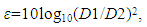 | (1) |
 | Figure 1. Constellation sharing |
3. Signal Shaping [20, 21]
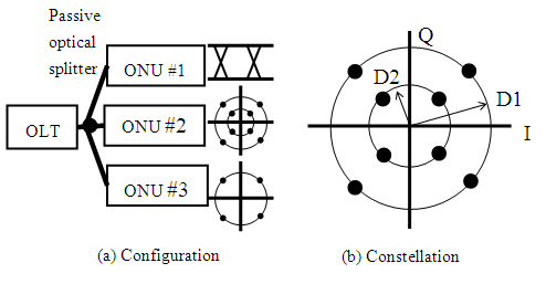
- Signal shaping aims to reduce the signal power without increasing the BER [20, 21]. In the conventional system design, the least average signal power is desired, since the transmit power causes crosstalk noise in the transmission line. Signal shaping efficiently controls the power by employing the well-known error correcting code. It is based on shaping the regions of the constellation, which is divided into M regions, as shown in Figure 2. Each region has equal area, i.e. the same number of symbols. Assuming the regions are numbered from s=0 to M-1, starting from the innermost one, the symbols in region s=0 bear the least power. Using the M regions of the constellation, an N-tuple of the region number with MN possible sequences can express N consecutive symbols. Given that the data sequence of K bits is transferred, 2K sequences with least energy can be selected from all sequences. To realize this, the symbols are selected from the innermost possible regions, i.e. the lowest region numbers.
 | Figure 2. Partitioning the constellation into M regions |
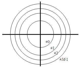
 | Figure 3. Signal shaping block diagram |
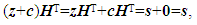
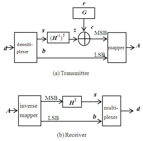 | Figure 4. Trellis shaping system |
 | (2) |
 | (3) |
 | (4) |
4. Signal Shaping in Constellation Sharing
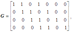
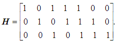
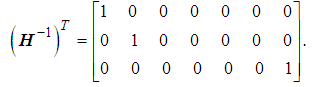
- In the PON system described in Figure 1, the existing OLT and ONU use OOK coding, which require extinction ratios as large as 20 dB to realize low BER. On the other hand, the large extinction ratio makes it difficult to discriminate the phase information among different symbols, when they are OFF. This paper introduces a signal shaping algorithm to solve this problem. Provided the constellation is divided into two regions, i.e. M=2, and the data word d is the connection of s and b, s and b are expressed as region number (radius) and argument (phase) in the constellation, respectively. In other words, s and b denote the OOK signals and PSK signals, respectively. In the shell mapping approach, s is encoded to s’, where each bit of s’ is used as a new MSB of the transmitted symbol, and the parameters are set to K=2 and N=3. Shell mapping defines the one to one mapping of s to s’ as follows; the values of s such as (0,0), (0,1), (1,0), and (1,1) are encoded to s’ of (0,1,1), (1,0,1), (1,1,0), and (1,1,1), respectively. The result maximizes the Euclid distance among the symbols by mapping “1” to the outer region of the constellation. Since commercial electric power is supplied to the OLT and ONU in the PON network, power consumption is a small factor in designing the system.In the trellis shaping approach, the shaping algorithm selects the largest BCD of coset member so that the symbols carry the largest power and maximize the Euclid distance among symbols in Figure 2. As an example, the binary (7, 4) hamming code can be applied to the shaping algorithm. Its generator matrix G and the respective parity-check matrix H are given as
 | (5) |
 | (6) |
 | (7) |
5. OptSim and MATLAB Co-simulation
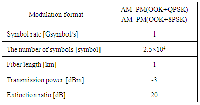
- Simulations were carried out by using OptSim and MATLAB software. OptSim is an advanced optical communication system simulation package designed for professional engineering and emerging optical systems [23]. In this work, signal shaping is carried out by MATLAB while OptSim simulates the optical devices, such as continuous wave (CW) laser, amplitude modulator, Raised Cosine filter, optical fiber, and Positive-Intrinsic-Negative (PIN) receiver. The network configuration shown in Figure 1 is assumed, where the OLT is connected to three ONUs via a 1:4 optical splitter and standard single mode fiber. The modulation format is shown in Figures 5(a) and (b), where one bit signal (MSB), denoted by s, is modulated using OOK, and the amplitude of the signal expresses the bit. In contrast, the phase represents two bits by using QPSK or three bits by 8PSK, as shown in Figures 5(a) and(b), respectively.
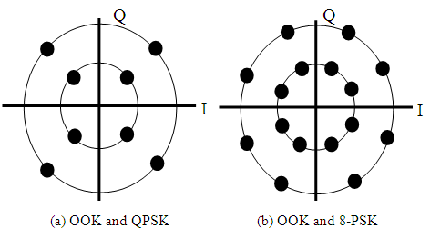 | Figure 5. Constellation |
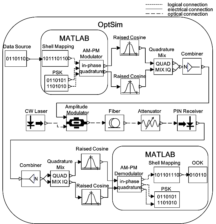 | Figure 6. Simulation setup schematics |
|
6. Simulation Results and Discussion
- This section describes the two-dimensional distribution of the signals and BER characteristics to show the effect of signal shaping.
6.1. Two-Dimensional Distribution of Signals
- As described above, the MSB of the data is modulated by OOK and is shaped by shell mapping or trellis shaping; the other bits are PSK modulated. The distributions of the transmitted symbols are shown in Figures 7(a) to (d). The height of the vertical bar shows the probability density of each signal. In these figures, the probability of the signals in the outer region is three times larger than that in the inner region. This implies that the probability of the signals in the inner region is quite low, which minimizes the BER degradation of the PSK signals.
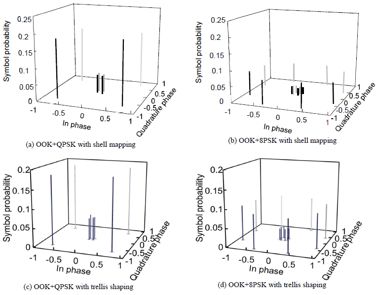 | Figure 7. Symbol probability in constellation sharing |
6.2. BER Characteristics of PSK Signal
- Using the simulation configuration described in Section 5, the BER characteristics of QPSK and 8PSK signals are measured with shell mapping or trellis shaping in constellation sharing. Additionally, the BER without signal shaping is also derived as a reference. Regarding shell mapping, the result of QPSK+OOK is shown in Figure 8(a), and that of OOK+8PSK is shown in Figure 8 (b), respectively. These figures show that OOK+QPSK with shell mapping achieves the received power gain of 1.4 dB at BER of 10-2 and 0.8 dB at BER of 10-3. The received power gain values of OOK+8PSK in this environment is 1.8 dB at BER of 10-2 and 0.9 dB at BER of 10-3. On the other hand, with trellis shaping, the result of QPSK+OOK is shown in Figure 8(c), and that of OOK+8PSK is shown in Figure 8(d), respectively. These figures show that the received power gain is 3.3 dB at the BER of 10-2 and 1.7 dB at BER of 10-3 in the constellation sharing of OOK and QPSK, and the gain is 3.8 dB at BER of 10-2 and 1.7 dB at BER of 10-3 in OOK+8PSK. These results show the improvement in BER possible with constellation sharing of OOK and PSK where an existing PON coexists the next generation system technology.
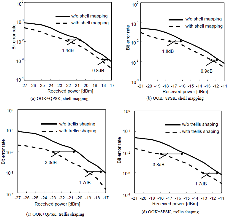 | Figure 8. BER of PSK signals with constellation sharing |
6.3. Discussion
- As described in section 2, constellation sharing reduces the Euclidian distance of the PSK symbols and degrades the BER of the PSK signals, when the symbols are OFF. According to the proposal of the use of signal shaping, the MSB of the data is modulated by OOK and is shaped by shell mapping or trellis shaping; the other bits are PSK modulated. The shaping algorithm selects the symbols in the outer region so that the symbols carry the largest power and maximize the Euclid distance among symbols. In fact, the probability of the signals in the outer region is three times larger than that in the inner region, as discussed in section 6.1. This shows that the probability of the signals in the inner region is quite low, which minimizes the BER degradation of the PSK signals. The measured BER characteristics show the improvement by applying the shell mapping and trellis shaping algorithms, as discussed in section 6.2. The above results clarified that both shaping algorithms, shell mapping and trellis shaping, increase the distribution of the signals in the outer region of OOK+PSK constellation sharing. In addition, the BER characteristics of PSK improve by more than 1 dB with shell mapping compared to that without shaping, and the improvement is more than 3 dB with trellis shaping. These results show that trellis shaping offer larger BER improvement than that shell mapping. One of the disadvantages of signal shaping is that the increase in the code rate reduces the signal efficiency. For example, use of the (7, 4) hamming code expands data s of 3 bits to z+c, i.e. 7 bits, so the OOK signal efficiency is 0.43. This implies that signal shaping improves the BER of PSK signals at the cost of OOK signal efficiency. Regarding the total efficiency of OOK+4PSK, it is 0.8. In the environment of next generation PON and the existing system co-existence, since PSK signals represent more bits than OOK, the former’s improvement far outweighs the latter’s penalty.
7. Conclusions
- This paper compared shell mapping and trellis shaping for symbol mapping to improve the transmission characteristics of the next generation Passive Optical Network (PON) system when co-existing with the conventional one. The mapping proposal solves one of the most critical problems; the small Euclid distance of the PSK signals in a constellation shared by OOK and PSK. The conventional system uses OOK for its simplicity, while the next generation uses advanced techniques such as PSK.This paper described the configuration, operation principle, and co-simulation architecture of MATLAB and OptSim for clarifying the improvement achieved by the mapping proposal. The co-simulation clarified the BER characteristics of the PSK improve by more than 1 dB with shell mapping compared to that without shaping, and the improvement is more than 3 dB with trellis shaping. These results show that trellis shaping offers larger BER improvement than shell mapping. The proposal will make the co-existence of the existing PON and the next generation technology practical.
ACKNOWLEDGEMENTS
- This work was supported by JSPS KAKENHI Grant (C) Number 26420377 and by the Nanzan University Pache Research Subsidy I-A-2 for the 2016 Academic year, for which the authors would like to express their thanks.