Tetsuo Shiotsuki 1, Nobuhiro Ohe 2
1Department of Robotics and Mechatronics, Tokyo Denki University, Adachi-ku, Tokyo, Japan
2Melco Techno Yokohama Co. Ltd., Kanagawa, Japan
Correspondence to: Tetsuo Shiotsuki , Department of Robotics and Mechatronics, Tokyo Denki University, Adachi-ku, Tokyo, Japan.
| Email: |  |
Copyright © 2016 Scientific & Academic Publishing. All Rights Reserved.
This work is licensed under the Creative Commons Attribution International License (CC BY).
http://creativecommons.org/licenses/by/4.0/

Abstract
A new control structure for real-time control systems over computer network is proposed. In general computer network has no real-time property for data exchange. Thus the construction of feedback system over the computer network can be considered as a design of hybrid system of real-time and non-real-time systems. Here a new structure of communication and control strategies are proposed. Remote controller sends not a single control input but a set of control inputs with time stamps as a datagram. Local controller receives the set of control inputs and chooses an appropriate input according to the arrival time. The effectiveness are demonstrated through the application of bilateral teleoperation system.
Keywords:
Networked Control System (NCS), Internet of Things (IoT), Real-Time control, Time stamp
Cite this paper: Tetsuo Shiotsuki , Nobuhiro Ohe , A New Structure of Networked Control System using Time Stamp, International Journal of Networks and Communications, Vol. 6 No. 1, 2016, pp. 13-18. doi: 10.5923/j.ijnc.20160601.03.
1. Introduction
Ubiquitous and broadband computer network has a mighty strength beyond our imaginations. Recently a lot of researchers discuss on networked control systems (NCS): feedback control systems constructed over the computer network. It is one of the challenges as a fusion of control engineering and information /communication technology. Bilateral tele-operation system is one of the interesting application of such a combined system [1] [2]. Tipsuwan and Chow discussed a variety of control methodologies and structures in NCS including issues caused by delay of data exchange [3] [4]. Mechanism of communication over the computer network is inherently type of event-driven process which does not have real-time performance. In spite of the property of computer network NCS requires real-time processing over the network in order to realize enough performance as stable as possible. Most of the discussion is an ability of extension of traditional control theory and synthesis for time delay process and prediction control. However some services on the Internet adopt the information of time stamp: data streaming, voice over the Internet, etc. Effective utilization of time stamp is one of the key technologies to overcome some problems of NCS.In this article we propose a new structure of data ex-change for NCS which uses time stamp information. We assume a hierarchical structure which consists of local controller and remote controller, here we name the former as controller side and the latter as plant side. Datagram send from plant side to controller side is a list of facts including time stamp. Datagram from controller to plant side is a set of commands that include time information. The problem on which we focus in this article is unpredictability of arrival time of the datagram caused by the feature of computer network. By using the information of time stamps the controller side can predict the behavior of plant side and can send a list of candidates of commands. The plant side can choose an appropriate command from the list of candidates according to the arrival time of the datagram and the contents of the command list. Here the method is proposed and effectiveness of the proposed methodology is demonstrated through the simulation and experiment.
2. Features of Computer Network
In general computer network system can be modeled as a mesh of nodes and links. Each node is a kind of computer system specialized for sending, receiving and relaying data between next node through physical data link. Figure 1 shows a typical layer model of network system consists of 4 nodes and 3 links. The data exchanging from source node to destination node is realized as a chain of copy functions between memories equipped on the nodes. These copying procedures are executed not only between the nodes but also the vertical layers as shown in Figure 1. These layers have each additional function: for example error detection/correction, packet assemble/ disassemble, resource reservation/release, acknowledgement of success/fail of missions, etc. In general these services are served for multi-users by sharing the hardware/software resources.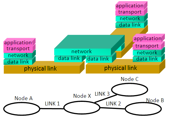 | Figure 1. Typical layer model of network system consists of 4 nodes and 3 links |
Because of the sophisticated mechanism the behavior is so complicated that the prediction of the time-delay between source and destination nodes is so difficult. Figure 2 shows a sample of round trip time (RTT) between nodes on the Internet [5]. In this case the minimum value is about 30 msec and most of the packets take a time between 30-500 msec. However the number of packets which take more than 1 sec is not so small that can be ignored (long tail). Moreover some packets take infinity time (packet loss).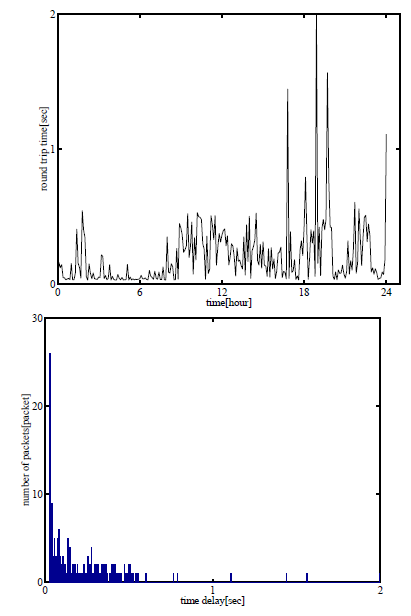 | Figure 2. Time delay of packets over the Internet in TCP/IP proto-col: (upper) behaviour: time[hours] vs time-delay[sec], (lower) histo-gram: time delay[sec] vs number of packets |
3. Proposal of a Communication System
3.1. Structure of a System
A proposed NCS structure is shown in Figure 3. The system consists of several modules; they are categorized into the control object (or plant) side and the controller side by communication network. In the rest of the paper we call them as plant side and controller side each other. They have modules for exchanging data each other to construct a feedback control mechanism (transmitter/ receiver). 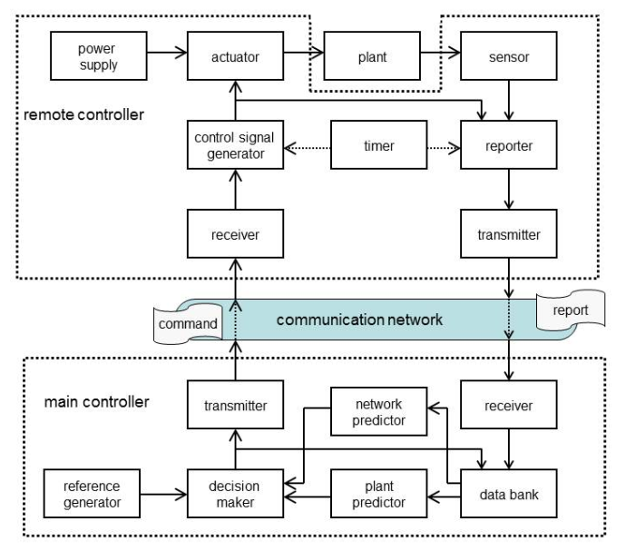 | Figure 3. Structure of proposed NCS |
The plant side includes time manager, executive module, data acquisition/report manager. And the controller side includes data bank, predictors, and decision making module. Their functions are explained in the following sections. The data from plant side to controller side includes identification of received data, sensor outputs, executed control inputs and other information in the plant side. Each data is encapsulated in the format as 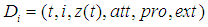 | (1) |
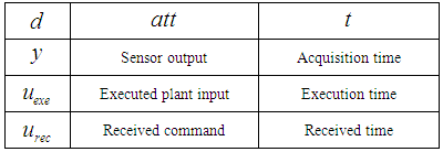
where t : the time attached to the data, i : sequence number, z(t): value of the data, att : attribute (sensor output, executed input,...), pro: property, ext: additional information.The value of t is decided by time manager in the plant side. Other modules in the side fetch the value of t at the moment of data generation. For example the t of sensor output is the time of data acquisition. The content corresponds to one of the values listed in Table 1.Table 1. Contents of the encapsulated data Di
 |
| |
|
The latency caused by the process from data generation to obtaining t is assumed to be zero (negligible small). This assumption is valid if the plant side modules are created as software modules implemented on single computer and connected via high speed communication bus or shared memory. Several protocols are well-known which ensure real-time property for communication on the Internet. For example RTP (Real Time Protocol) [6], RTSP (Real Time Streaming Protocol) [7], CRTP (Com-pressed RTP) [8], et al. These protocols are practically implemented and utilized for data streaming and VoIP(Voice over IP) and effective to eliminate jitter (fluctuation of latency). But the effectivity to net-worked control system is not reported yet.
3.2. Data Bank of Time Stamped Data
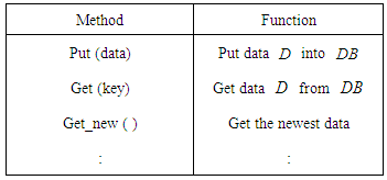
Data bank is a storage unit which saves historical data obtained from plant side. NCS on the Internet can be considered as a hybrid system of real time and non-real-time system and the data exchange between plant and controller sides is not synchronized. Even if each packet is transmitted at fixed intervals the arrival time and the order at the receiver may be irregular. Thus the time information corresponding to the behavior of the plant side and arrival/ departure time of the packets on the communication system must be interpreted independently. DBMS (Data Base Management System) is a candidate of the structure to overcome this issue. In order to reduce the effects caused by latency simple Data Bank module is implemented for the NCS. This module consists of a table of received data in equation (1) and some methods (functions) listed in Table 2. | (2) |
Table 2. Examples of the Methods for Data Bank DB method function
 |
| |
|
3.3. Prediction of Plant Behavior
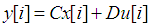
According to the historical data of the plant side the future behavior of the plant can be predicted under some assumptions. It is well known that the plant with state space model 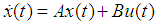 | (3) |
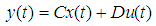 | (4) |
has the behavior expressed as follows.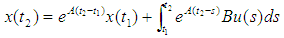 | (5) |
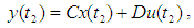 | (6) |
where  are some points in the time axis. Now define notations
 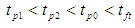 as the past time 1, 2, preset time and future time, respectively. The relations between them are shown in Figure 4. Assume that the behavior
  in the past time interval
  is obtained previously. The output at the future time
  is obtained as
  | (7) |
This equation says that  depends on the initial state
  , the known data
 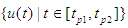 and unknown data
 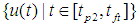 . It means that the prediction requires state estimate for
  and assumption of unknown input
  at the interval
  .
.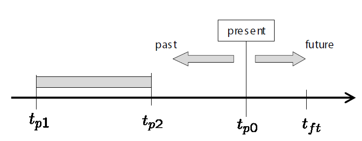 | Figure 4. Location on the time axis |
In Figure 4, if the communication system has neither packet loss nor jitter, and if the data  in (1) is obtained in periodic intervals regularly, that is
 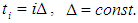 , the behavior of the system can be expressed in a discretized model of the plant in (4) as
 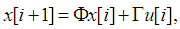 | (8) |
 | (9) |
where 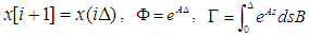 .In this case the estimation procedure for initial state
  is reduced to the recursive calculation by using traditional state observer. In order to count the jitter and packet loss some kind of modifications must be discussed. The following description is a candidate of the modification.
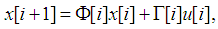 | (10) |
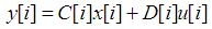 | (11) |
where  ,
,  are state and measurement at time
  and
and  ,
,  are constant value exerted during interval
  .
.  and
and  are state transition parameter which vary according to the effect of jitter. If the time stamps
  and plant parameters (A, B) are obtained, the parameters are derived by
 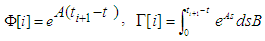 . This means that the equation (11) is available for estimation of plant behavior.
3.4. Prediction of Network Behavior
According to our observations, the behavior of computer network consists of predictable part and probabilistic part. For example the latency in Figure 2 can be considered as a sum of physically minimum value and random value. Pareto distribution is a candidate of this behavior [5]. Suitable model depends on many factors; for example: combination of source and destination nodes, feature of physical layer, performance of switching nodes, protocol and its parameters, congestion of the network, size of packet, and so on. The modeling and prediction of the behavior of computer network is now open problem, and the development makes it difficult.
3.5. Control Depending on Arrival Time
As discussed above the latency is not deterministic but probabilistic. This means that the arrival time of the packet from controller side to plant side can not be known before hand, and the practical arrival time  will be settled just after reaching of the packet to the plant side. Note that all the time stamp
  are measured by the clock in plant side.Thus the time-delay between arrival time
  and any data in (1) can be decided exactly. For example the time delay between arrival time
  and data acquisition time
  in
in  is exactly
 where
where  is a sequence number of the data. This means that the control input
  can be determined as a function of time-delay
  , and the control problem can be reduced to that of time-delay systems control in traditional control theory. Figure 5 shows a simple example of feedback control system. The plant is a first-order LTI system with time-delay
  . Constant feedback gain
  constructs a feedback system. In order to keep the stability of the closed loop system there is upper limit of constant feedback gain
  .Unfortunately the time delay
  is indeterminate in controller side. Assume that the arrival time
  is distributed in the interval
  . The distribution of the time delay can be expressed as
  . Thus the control input is obtained as a function of arrival time
  Remark: If
  then large value of the input is utilized, which corresponds to high gain feedback strategy.Contrary if
  then magnitude of the input is limited.
  means the case of packet loss, unreachability or network failure. In this case
  , which means that the case of ill condition of the network adopt no control. This strategy is effective in the case that the plant is inherently stable or stabilized by local feedback control.
 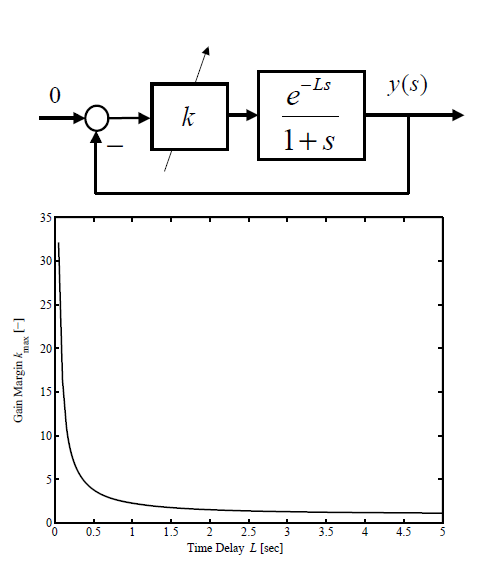 | Figure 5. Stability condition: time-delay L vs feedback gain K |
3.6. Control Signal Generator and Report Generator
The control input w.r.t. plant output  will be sent as a set of candidates as
  In practice the set
  is implemented as a table of
  or a programming code of function. the module of control signal generator makes the procedure as(1) accept the received data
  , (2) get arrival time
  from the clock in plan side,(3) check
  and
and  , and determine a control input
  ,(4) exert the input to the plant
  .Many events occur in plant side: receive data
  , determination of control input
  , drive control actuator, acquisition of plant output
  , and so on. The module of report generator summarized these events as a report with the contents in equation (1).
4. Simulation and Experiment
4.1. Experimental Tools and Method
Simple estimation procedure based on equation (11) is adopted on an experimental system of force communication system as shown in Figure 6.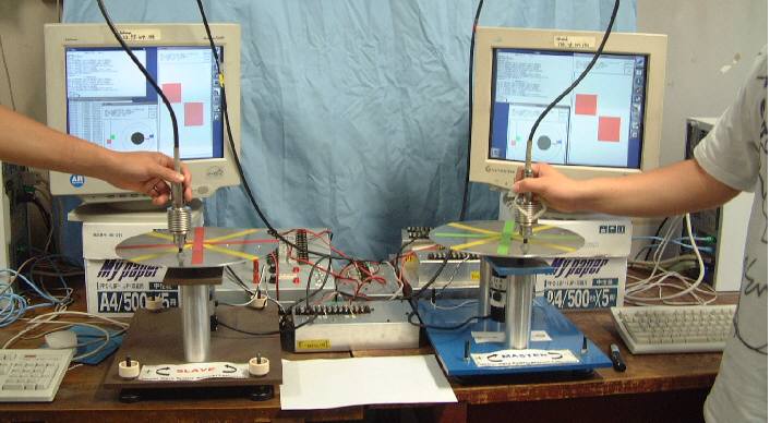 | Figure 6. Force communication system over digital computer network with data exchange latency 400msec |
Force communication over the computer network is a very important challenge for tele-operation and/or multi-media communication systems. It will give a big influence not only to industries but also to welfare, education, communication etc. The system consists of two controllers and two force communication devices. These computers work as not only device controllers but also data exchange devices. Two computers are connected to the Internet and can exchange messages each other. Each computer has one force communication device which can generate force and detect the angle of the rotational disk. Locally feedback control systems are constructed which works as force sensing and position control system. The controller design procedure has the following features [1] [2].(i) Structure: The same simple feedback controller is collocated at each disk which has DC servo motor and rotary encoder for toque generation and position detection.(ii) Control law: Each controller reduces position error between two disks.(iii) Parameters: Controller parameters are determined by using H_∞ robust control theory with the following robustness.(iv) Robustness: Robust with respect to some range of variation of time-delay (transmission latency), parameter uncertainty of the plant.In order to improve the robustness the proposed prediction procedure are implemented. Figure 7 shows an effect of prediction procedure. The upper figure is the case of no prediction module and the lower with prediction of 40 steps (200msec). The local controllers execute control algorithm in control period 5msec. They exchange the data Di including position and time stamp every 10msec with latency 400msec.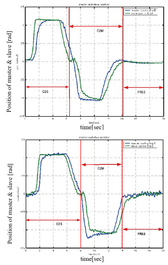 | Figure 7. An effect of prediction of the plant behavior. (above: no compensate, below: 40steps prediction) |
The intervals notated as C2S/C2M in figure 7 indicate the direction of the operation of master-slave system. C2S means the interval in which an operator grasps the stick of the left disk and rotate it. Then the right disk rotate in order to follows the motion of the left disk. C2M means the opposite direction. The interval noted as Free means that in which nobody touches neither disk.
4.2. Results and Discussion
The difference at the rising point in the intervals C2S and C2M demonstrates the effectiveness of the prediction mechanism. The shape of the trajectories of follower side is sharper than the other, which means that the prediction method affects to the response curve. On the other hand the behavior in the interval Free indicates the robustness with respect to the latency of data exchange between controllers. In case of prediction module the response of the disks are noisy and rather unstable than no prediction.According to the experimental result, utilization of time stamp and prediction are well implemented and the effectiveness are demonstrated. Especially improvement of transient response is confirmed in spite of the presence of data exchange latency. It means that the prediction method is effective to improve the performance of response speed. However the stability might be weaken because of the well-known property of predictors.
5. Conclusions
In this article a new control structure for real-time control systems over computer network was proposed. The feature of the system is the contents of the data from controller side to plant side, which includes a set of candidates of control input. Combining the data format with other proposed modules the ambiguity caused by the latency of computer network can be eliminated. There is a trade-off between the size of datagram and the robustness w.r.t. the ambiguity of latency. The development of information and communication technologies are enabling broadband communication and mass data exchange. Thus the proposed control systems structure has good prospects for the future. For example it is possible to extend the set of datagram consists of not only the candidate of the control input but also the set of solutions. Thus receiver may choose an appropriate solution w.r.t. the arrival time. Such a mechanism realizes real-time application on the non-real-time platform.
References
| [1] | Shiotsuki, T. 2004, Force Communication over the Computer Network, 3rd IFAC Symposium on Mechatronic Systems, Manly Beach, Sydney, Australia, 353-358. |
| [2] | Shiotsuki, T. 2004, For the fusion of information Networks and control theory, Journal of SICE (in Japanese), Vol.43, No.6, 465- 468. |
| [3] | Tipsuwan, Y., Chow, M.-Y., 2003, Control methodologies in networked control systems, Control Engineering Practice 11, 1099–1111, Elsevier Science Ltd. |
| [4] | Gupta, R.A., Chow, M.-Y., 2010, Overview of Networked Control Systems, Chapter 1 in Networked Control Systems- theory and Applications ( Ed. Wang, F.-Y., Liu, D.), Springer. |
| [5] | T. Tajima, T. Shiotsuki, 2004, Statistic properties of latency on computer network, SICE 4th Annual Conference on Control Sys-tems, 437-440, Kitakyushu. |
| [6] | H. Schulzrinne, et. al, (Audio-Video Transport Working Group of IETF), 1996, RTP: A Transport Protocol for Real-Time Applica-tions, RFC1889, http://www.ietf.org/rfc/rfc1889.txt. |
| [7] | H. Schulzrinne, et. al, 1998, Real Time Streaming Protocol (RTSP), RFC2326, http://www.ietf.org/rfc/rfc2326.txt. |
| [8] | S. Casner, V. Jacobson, 1999, Compressing IP/UDP/RTP Headers for Low-Speed Serial Links, RFC2508, http://www.ietf.org/rfc/rfc2508.txt. |

 Abstract
 Reference
 Full-Text PDF
 Full-text HTML